 English
 Espaol
 Franais
 阿拉伯
阿拉伯 中文
中文 Deutsch
 Italiano
 Português
 日本
日本 韩国
韩国 български
 hrvatski
 esky
esky Dansk
Dansk Nederlands
 suomi
suomi Ελληνικ
 印度
印度 norsk
norsk Polski
 Roman
Roman русский
 Svenska
Perkins2306柴油发动机威尔逊P550柴油发电机配件CH10929滤清器供应商,Perkins2306柴油发动机威尔逊P550柴油发电机配件CH10929滤清器技术价格规格咨询服务,Perkins2306柴油发动机威尔逊P550柴油发电机配件CH10929滤清器零配件供应,Perkins2306柴油发动机威尔逊P550柴油发电机配件CH10929滤清器售后服务中心,Perkins2306柴油发动机威尔逊P550柴油发电机配件CH10929滤清器,Perkins2306柴油发动机威尔逊P550柴油发电机配件CH10929滤清器详细的技术参数,

产品中心
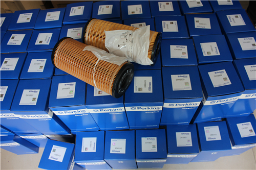
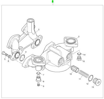
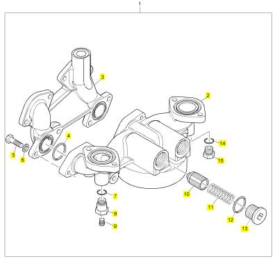
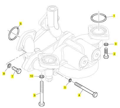
Perkins2306柴油发动机威尔逊P550柴油发电机配件CH10929滤清器
详细描述
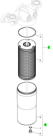
项目 零配件号码 新件号 描述
CH11139 1 CH12010 密封O型圈
1 CH10929 1 CH10929 滤清器
1 CH10929 1 CH10929 滤清器
4 KRP1719 1 KRP1719 滤清器组合 01/12/2011
4 KRP1570 1 KRP1719 过滤器壳 30/11/2011
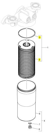
项目 零配件号码 新件号 描述
2 1 滤清器
3 CH12010 1 CH12010 密封垫
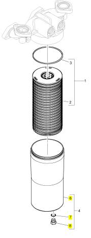
项目 零配件号码 新件号 描述
6 1 过滤器壳
7 CH10046 1 CH10046 密封O型圈
8 CH10284 1 CH10284 栓塞
项目 零配件号码 新件号 描述
1 CH11250 1 CH11250 燃油滤清器
项目 零配件号码 新件号 描述
2 1 燃油滤清器
3 CH10818 1 CH10818 燃油滤清器
4 CH10316 2 CH10316 密封O型圈
5 CH10567 4 CH10567 螺拴
6 CH10541 4 CH10255 垫圈
7 CH10133 1 CH10133 密封O型圈
8 CH10888 1 CH10888 承接器
9 CH10262 1 CH10262 栓塞
10 CH10513 2 CH10513 放泄阀
11 CH10819 2 CH10819 弹簧
12 CH10091 2 CH10091 密封O型圈
13 CH10291 2 CH10291 栓塞
14 CH10133 1 CH10133 密封O型圈
15 CH10284 1 CH10284 栓塞
项目 零配件号码 新件号 描述
1 T400222 2 T400222 密封O型圈
1 CH10816 2 CH10816 密封O型圈
2 CH10567 2 CH10567 螺拴
3 CH10255 2 CH10255 垫圈
3 CH10541 2 CH10255 垫圈
4 CH10814 2 CH10814 螺拴
5 CH10255 2 CH10255 垫圈
5 CH10541 2 CH10255 垫圈
6 CH10224 2 CH10224 密封O型圈
7 CH10815 4 CH10815 螺拴
8 CH10255 4 CH10255 垫圈
8 CH10541 4 CH10255 垫圈
9 CH10751 2 CH10751 螺拴
10 CH10255 2 CH10255 垫圈
10 CH10541 2 CH10255 垫圈
Note: A sight glass in the low pressure supply line is
helpful in diagnosing air in the fuel.
4. Cold weather adversely affects the characteristics
of the fuel. Refer to the Operation and
Maintenance Manual for information on improving
the c haracteristics of the fuel during cold weather
operation.
5. Check the fuel pressure during engine cranking.
Check the fuel pressure after the fuel filter. Refer
to Systems Operation, Testing and Adjusting,
“Fuel System” for the correct pressure values. If
the fuel pressure is low, replace the fuel filters. If
the fuel pressure is still low, check the following
items: fuel transfer pump, fuel transfer pump
coupling, and fuel press ure regulating valve.
Air Inlet and Exhaust System
1. Check for an air filter restriction. Clean plugged air
filters or replace plugged air filters. Refer to the
Operation and Maintenance Manual for additional
information.
2. Check the air inlet and exhaust system for
restrictions and/or for leaks. Refer to Systems
Operation, Testing and Adjusting, “Air Inlet and
Exhaust System”.
i02557763
Engine Oil in Cooling System
Probable Causes
• Engine oil cooler core
• Cylinder head gasket
Recommended Actions
Engine Oil Cooler Core
1. Inspect the engine oil cooler c ore for leaks. If a
leak is found, replace the oil cooler core. Refer to
Disassembly and Assembly, “Engine Oil Cooler
- Remove” and Disassembly and Assembly,
“Engine Oil Cooler - Install”.
2. Drain the crankcase and refill the crankcase with
clean engine oil. Ins tall new engine oil filters.
Refer to the Operation and Maintenance Manual
for more information.
Cylinder Head Gasket
1. Remove the cylinder head. Refer to Disassembly
and Assembly, “Cylinder Head - Remove” for the
correct procedure.
2. Check the cylinder liner projection. Refer to
Systems Operation, Testing and Adjusting for the
correct procedure.
3. Install a new cylinder head gasket and new water
seals in the spacer plate. Refer to Disassembly
and Assembly, “Cylinder Head - Install” for the
correct procedure.
i02557773
Engine Vibration
Probable Causes
• Vibration damper
• Engine supports
• Driven equipment
• Engine misfiring or running rough
Recommended Actions
Vibration Damper
Check the vibration damper for damage. Install a
new vibration damper, if necessary. Inspect the
mounting bolts for damage and/or for wear. Replace
any damaged bolts. Refer to the Disassembly and
Assembly manual.
Engine Supports
Inspect the mounts and the brackets while you run
the engine through the speed range. Look for mounts
and brackets that are loose and/or broken. Tighten
all of the mounting bolts. Install new components, if
nec essary.
Driven Equipment
Check the alignment and the balance of the driven
equipment.
Engine Misfiring or Running Rough
Refer to the Troubleshooting Guide, “Engine Misfires,
Runs Rough or Is Unstable”.
This document has been printed from SPI². Not for Resale
![]() 40
40
Troubleshooting Section
KENR6224
Engine Will
Not Crank
i02557776
Hydraulic Cylinder Lock
Check for fluid in the cylinders (hydraulic cylinder
lock) by removing the individual electronic unit
injectors.
Note: Drain the fuel from the cylinder head. Fuel will
Probable Causes
• Batteries
• Battery cables
• Starting circuit
• Starting motor solenoid
• Starting motor
• Flywheel ring gear
• Hydraulic cylinder lock
• Internal engine fault
Recommended Actions
Batteries and/or Battery Cables
1. Inspect the main power switch, battery posts,
and battery cables for loose connections and
for corrosion. If the battery cables are corroded,
remove the battery cables and clean the battery
cables. Tighten any loose connections.
2. Inspect the batteries.
a. Charge the batteries. Refer to local operating
procedures.
b. Load test the batteries. Refer to local operating
procedures.
Starting Motor Solenoid or Starting
Circuit
1. Test the operation of the starting motor solenoid.
2. Check the wiring to the starting motor solenoid.
Starting Motor or Flywheel Ring Gear
1. Test the operation of the starting motor.
2. Inspect the pinion on the starting motor pinion and
the flywheel ring gear for damage.
flow from the cylinder head into the cylinders when
the electronic unit injector is removed.
Internal Engine Fault
Disassemble the engine. Refer to the Disassembly
and Ass embly manual. Inspect the internal
components for the following conditions:
• Seizure
• Broken components
• Bent components
i02557812
Excessive Black Smoke
Probable Causes
• Flash file
• Position sensors
• Atmospheric pres sure sensor
• Inlet manifold pressure sensor
• “Fuel Position” and/or “FRC Fuel Limit”
• Fuel quality
• Valve adjustment
• Air inlet or exhaust system
Recommended Actions
Flash File
Verify that the correct flash file is installed. Refer to
the Troubleshooting Guide, “Flash Programming” for
information.
Position Sensors
1. Check the calibration of the position sensors.
Refer to Troubleshooting, “Engine Position
Sensors - Calibrate”.
This document has been printed from SPI². Not for Resale
![]() KENR6224
KENR6224
41
Troubleshooting Section
2.
Verify that the crankshaft and the camshaft drive
gears are set with the proper orientation. Refer to
a.
Check for an air filter restriction.
the Disassembly and Assembly manual.
Atmospheric Pressure Sensor
1. Remove the sensor.
2. Remove debris, moisture, or ice from the sensor.
3. Install the sensor.
4. Check the electronic service tool for active
diagnostic codes on the sensor. If no active
diagnostic code exists, the sensor may be used.
The correct reading for the atmospheric pressure
is between 50 kPa (7.25 psi) and 100 kPa
2.
3.
4.
b. Perform a visual inspection of the system for
restrictions and/or for leaks in the air inlet
piping .
Ensure that the turbocharger is in good repair.
Check the exhaust sy stem for restrictions.
Repair any leaks that were found. Remove
any restrictions that were found. Replace any
damaged components that were found.
i02558234
(14.5 psi).
Excessive
Engine
Oil
Inlet Manifold Pressure Sensor, “Fuel
Position”, and/or “FRC Fuel Limit”
1. Monitor the status of “Fuel Position” and “Rated
Fuel Limit” while the engine is operating under full
load. If “Fuel Position” equals “Rated Fuel Limit”
and “Fuel Position” is less than “FRC Fuel Limit”,
the Electronic Control Module (ECM) is providing
the correct control. Otherwise, proceed to the next
Step.
2. Verify that there are no active diagnostic codes for
the inlet manifold pressure sensor.
3. Monitor the status of “Boost Pressure” and
“Atmospheric Pressure” on the electronic service
tool. When the engine is not running, “Boost
Pressure” should be 0 kPa (0 psi).
Note: A fault with the “FRC Fuel Limit” will only cause
black smoke during acceleration. A fault with the
“FRC Fuel Limit” will not cause black smoke during
steady state operation.
Fuel Quality
Cold weather adversely affects the characteristics
of the fuel. Refer to the Operation and Maintenance
Manual for information on improv ing the
characteristics of the fuel during cold weather
operation.
Valve Adjustment
Check the valve adjustment. Refer to Sy stems
Operation, Testing and Adjusting for information on
valve adjustments.
Air Inlet or Exhaust System
1. Check the air inlet system for restrictions and/or
for leaks.
Consumption
Probable Causes
• Oil leaks
• Oil level
• Engine oil cooler
• Turbocharger
• Valve guides
• Piston rings
• Incorrect installation of the compression ring and/or
the intermediate ring
Recommended Actions
Oil Leaks
Loc ate all oil leaks. Repair the oil leaks . Chec k for a
dirty crankcase breather.
Oil Level
Inspect the engine oil level. Remove any extra oil
from the engine. Recheck all fluid levels.
Engine Oil Cooler
Check for leaks in the engine oil cooler. Check for oil
in the engine coolant. If necessary, repair the engine
oil cooler.
This document has been printed from SPI². Not for Resale
![]() 42
42
Troubleshooting Section
KENR6224
Turbocharger
Check the air inlet manifold for oil. Check for oil
leakage past the seal rings in the impeller end of
the turbocharger shaft. If necessary, repair the
turbocharger.
Valve Guides
If the valve guides are worn, repair the cylinder head.
Refer to Disassembly and Assembly, “Inlet and
Exhaust Valve Guides - Remove and Install”.
Piston Rings or Incorrect Installation
of the Compression Ring and/or the
Intermediate Ring
Inspect the internal engine components. Replace any
worn components.
i02558236
Excessive Fuel Consumption
Probable Causes
• Engine operation
• Fuel leaks
• Fuel quality
• Engine speed/timing
• Electronic unit injectors
• Air inlet and exhaust system
• Accessory equipment
Recommended Actions
Engine Operation
Use the electronic serv ice tool to check the “Current
Totals” for a high load factor which would be indicative
of poor operating habits.
Note: Engine operation may also be affected by
environmental conditions such as wind and snow.
Fuel Leaks
Check the fuel pressure during engine cranking.
Check the fuel pressure after the fuel filter. Refer to
Systems Operation, Testing and Adjusting for the
correct pressure values. If the fuel pressure is low,
replace the fuel filters. If the fuel pressure is still low,
check the following items : fuel transfer pump, fuel
transfer pump coupling, and fuel pressure regulating
valve.
Fuel Quality
Cold weather adversely affects the characteristics
of the fuel. Refer to the Operation and Maintenance
Manual for information on improving the
characteristics of the fuel during cold weather
operation.
Engine Speed/Timing
Perform a calibration of the position sensor. Refer to
the Troubleshooting Guide, “Engine Position Sensor
- Calibrate”.
Electronic Unit Injectors
1. Check for correct installation of the J1/P1
and J2/P2 Electronic Control Module (ECM)
connectors and the electronic unit injector
connectors. Refer to the Troubleshooting Guide,
“Electrical Connectors - Inspect”.
2. Perform the “Injector Solenoid Test” on the
electronic s ervice tool in order to determine if all
of the injector solenoids are being energized by
the ECM.
3. Perform the “Cylinder Cutout Test” on the
electronic service tool in order to identify any
injectors that might be misfiring. Refer to the
Troubleshooting Guide, “Injector Solenoid Circuit
- Test”.
Air Inlet and Exhaust System
1. Inspect the air filter for a restriction. If the air filter
shows signs of being plugged, clean the air filter
or replace the air filter.
2. Check the air inlet and exhaust system for
restrictions and/or for leaks. Refer to Systems
Operation, Testing and Adjusting.
This document has been printed from SPI². Not for Resale
![]() KENR6224
KENR6224
43
Troubleshooting Section
Accessory Equipment
Check all accessory equipment for faults that may
create excess ive load on the engine. Repair any
damaged components or replace any damaged
components.
Note: If the camshaft is replaced, the valve lifters
must also be replaced.
3. Adjust the engine valve lash. Refer to Systems
Operation, Testing and Adjusting, “Engine Valve
Lash - Inspect/Adjust”.
Excessive
Valve Lash
i02558239
Excessive W hite
Smoke
i02558241
Probable Causes
• Lubrication
• Valve lash
• Valve train components
Recommended Actions
Lubrication
1. Remove the valve mechanism cover. Refer to
Disassembly and Assembly, “Valve Mechanism
Cover - Remove and Install”.
2. Check the lubrication in the valve compartment.
Ensure that there is adequate engine oil flow in
the valve compartment. The passages for the
engine oil must be clean.
Valve Lash
Adjust the engine valve lash. Refer to Systems
Operation, Testing and Adjusting, “Engine Valve Lash
- Inspect/Adjust”.
Valve Train Components
1. Inspect the following components of the valve
train:
• Roc ker arms
• Pushrods
• Valv e lifters
• Camshaft
• Valv e stems
• Roc ker shafts
2. Check the components for the following conditions:
abnormal wear, excessive wear, straightness, and
cleanliness. Replace parts, if necessary.
Note: Some white smoke may be pres ent during
cold start-up conditions when the engine is operating
normally. If the white smoke persists, there may be a
fault.
Probable Causes
• Diagnostic codes
• Flash file
• Starting aids
• Water temperature regulators
• Electronic unit injectors
• Fuel supply
• Cooling s ystem
• Component wear
Recommended Actions
Diagnostic Codes
Use the electronic servic e tool to check for active
diagnostic codes. Troubleshoot any active diagnostic
codes before continuing with this procedure.
Flash File
Verify that the correct flash file is installed in the
Engine Control Module (ECM). The flash file that
is installed in the ECM can be dis played on the
“Configuration” screen on the electronic service tool.
Starting Aids
Block Heater (If Equipped)
Ensure that the block heater is functioning correctly.
This document has been printed from SPI². Not for Resale
![]() 44
44
Troubleshooting Section
KENR6224
Water Temperature Regulators
Check the water temperature regulators for correct
operation. Refer to Systems Operation, Testing and
Adjusting, “Water Temperature Regulator - Test” for
the proper procedure.
Electronic Unit Injectors
Fuel Dilution of Engine
Probable Causes
Oil
i02558246
Use the electronic service tool to perform the cylinder
cutout test. Try to simulate the conditions for the test
that were experienced during operation. Cut out each
cylinder individually for approximately one minute in
order to isolate any misfiring cylinders. If the misfire
can be isolated to a specific cylinder, proceed to
Troubleshooting, “Injector Solenoid Circuit - Test”.
Fuel Supply
1. Monitor the exhaust for smoke while the engine
•
•
•
•
•
Seals on the case of the electronic unit injector or
on the barrel of the electronic unit injector
Seals on the fuel line adapter for the cylinder head
Electronic unit injector
Fuel supply manifold
Fuel transfer pump seal
2.
3.
4.
5.
is being cranked.
If no smoke is present, there may be a fault with
the fuel quality or there may be a fault in the fuel
supply.
Check the fuel pressure. Refer to Systems
Operation, Testing and Adjusting, “Fuel System
Pressure - Test”.
Ensure that the fuel system has been primed.
Refer to the Operation and Maintenance Manual,
“Fuel System - Prime” for the correct procedure.
Check for fuel supply lines that are restricted.
Cold weather adversely affects the characteristics
of the fuel. Refer to the Operation and
Maintenance Manual for information on improving
the c haracteristics of the fuel during cold weather
operation.
Recommended Actions
Seals on the Case of the Electronic Unit
Injector or on the Barrel of the Electronic
Unit Injector
Look for signs of damage to the seals for the
electronic unit injectors. Replace any seals that are
leaking.
Seals on the Fuel Line Adapter for the
Cylinder Head
Look for signs of damage to the seals on the fuel line
adapter for the cylinder head. Repair any leaking fuel
lines or components and/or replace any leaking fuel
lines or components.
Electronic Unit Injector
Look for signs of damage to the electronic unit
injectors. If necessary, repair the electronic unit
Cooling System
Check for an internal coolant leak. Check for coolant
in the engine oil, coolant in the cylinders, and coolant
in the exhaust system. Refer to Systems Operation,
Testing and Adjusting, “Cooling System - Test”.
Component Wear
Check the following components for excessive wear:
• Valves
• Pistons
• Rings
• Cylinder liners
injectors or replac e the electronic unit injectors.
Fuel Supply Manifold
Look for signs of damage to the fuel supply manifold.
Fuel Transfer Pump Seal
Ensure that the weep hole is not plugged. If
nec essary, repair the fuel transfer pump or replace
the fuel transfer pump.
This document has been printed from SPI². Not for Resale
|
45
Troubleshooting Section
Intermittent Engine
i02558247
Shutdown
•
•
•
J61/P61 Customer connectors
J300/P300 Connectors for the injector solenoid
harness
J401/P401 and J402/P402 Engine position
Note: Use this procedure only if the engine shut
down completely and it was necessary to res tart the
engine.
Probable Causes
• Diagnostic codes or event codes
• Operating c onditions
2.
sensor connectors
Check the associated wiring for the following
conditions: damage, abrasion, corrosion, and
incorrect attachment.
Refer to the Troubleshooting Guide, “Electrical
Connectors - Inspect”.
•
•
•
•
Electrical connections
Remote shutdown
Circuit breakers and fuses
Fuel supply
Note: Aftermarket engine protection devices usually
interrupt power to the ECM. Check for correct
installation and for operation of aftermarket engine
protection devices. It may be necessary to bypass
the aftermarket devices in order to continue testing.
Remote Shutdown
1. Access the s tatus screen that displays the remote
Note: If the fault only occurs under certain conditions
such as high engine speed, full load or engine
operating temperature, then perform the test under
those operating conditions.
Recommended Actions
2.
shutdown switch status. The remote shutdown
switch status on the electronic service tool is
called “Injection Disable”.
Refer to Table 8 and measure the voltage between
each terminal that is listed and the engine ground.
Diagnostic Codes or Event Codes
Certain diagnostic codes and/or event codes may
cause the engine to shutdown. Connect the electronic
servic e tool and check for active codes and/or for
logged codes. Troubleshoot any codes that are
present before continuing with this procedure.
Operating Conditions
The engine may be shut down due to low pressure
levels or other factors. Connect the electronic service
tool and c heck for active shutdowns or diagnostic
codes.
If a shutdown is ac tive, “Injection Disabled” will
appear in the third box of any status screen on the
electronic service tool.
An engine shutdown event will appear on a J1939
device if the device is capable of displaying diagnostic
codes.
Electrical Connect ions
1. Check the following connectors for proper
ins tallation:
• J1/P1 and J2/P2 connectors for the Electronic
Control Module (ECM)
Table 8
3. If the voltage is not in the proper range, refer to
Troubleshooting, “Switch Circuits - Test”.
Circuit Breakers and Fuses
Check the circuit breakers and fuses. The circuit
breakers may exceed the trip point due to
overheating. Reset the circuit breakers if the circuit
breakers are tripped. Replace any blown fuses.
Fuel Supply
Check for a fault in the fuel supply. Verify that the
fuel pressure is correct. Refer to Systems Operation,
Testing and Adjusting, “Fuel System Pressure - Test”
for additional information.
This document has been printed from SPI². Not for Resale
![]()
![]() 46
46
Troubleshooting Section
KENR6224
Low Engine Oil Pressure
NOTICE
i02558254
Oil Cooler
Check the oil cooler for plugging or blockage. Clean
the oil cooler core. If necessary, replace the engine
oil cooler. Refer to Disas sembly and Assembly, “Oil
Cooler - Remove” and Disassembly and Assembly,
“Oil Cooler - Install”.
Do not operate engine with low oil pressure. Engine
damage will result. If measured engine oil pressure
is low, discontinue engine operation until the fault is
corrected.
Probable Causes
• Engine oil level
• Engine oil filters and oil filter bypass valve
• Engine oil pump
• Engine oil cooler
• Fuel dilution
• Engine wear
Recommended Actions
Engine Oil Level
Inspect the engine oil level. If engine oil is low add
engine oil. Refer to the Operation and Maintenance
Manual.
Engine Oil Filters and Oil Filter Bypass
Valve
Check the service records of the engine for
information that is related to the last oil change. If
necessary, perform an oil change on the engine and
replace the engine oil filters.
Check the operation of oil filter bypass valve. Clean
the bypass valve and the housing. If necessary,
install new parts.
Engine Oil Pump
Check for blockage of the inlet screen for the engine
oil pump. Check the components of the engine oil
pump for excessive wear. If necessary, repair the oil
pump or replace the oil pump.
|
Check for presence of fuel in lubricating oil. Refer to
the Troubleshooting Guide, “Fuel Dilution of Engine
Oil”.
Engine Wear
Inspect the camshaft and/or camshaft bearings
for excessive wear. Inspect the crankshaft and/or
crankshaft bearings. Excessive wear to discrete
components may be an indication of a blocked oil
pas sage. Use an oil pressure gauge to check the
oil pressure at the main oil gallery. This will help
determine if the excessive wear is from low system
pressure or from passages that are blocked.
i02558264
Low Power
Probable Causes
• Diagnostic codes
• Event codes
• Engine rating
• Programmable parameters
• Cold mode
• Electrical connectors
• Circuit for electronic unit injectors
• Fuel supply
and/or FRC fuel position
• Air inlet and exhaust system
This document has been printed from SPI². Not for Resale
![]() KENR6224
KENR6224
47
Troubleshooting Section
Recommended Actions
Note: If the fault only occurs under certain conditions ,
test the engine under those conditions. Examples
of certain conditions are high rpm, full load and
engine operating temperature. Troubleshooting
the symptoms under other conditions can give
misleading results.
Diagnostic Codes and Event Codes
Certain diagnostic codes and/or event codes may
cause poor performance. Connect the electronic
service tool and check for active codes and for logged
codes. Troubleshoot any codes that are present
before continuing with this procedure.
Engine Rating
Verify that the correct engine rating is being used for
the application.
Programmable Parameters
Check the following parameter on the electronic
service tool:
• Desired speed input
Verify that the injector trim files are programmed.
Cold Mode
Monitor the status screen on the electronic service
tool in order to verify that the engine has exited cold
mode. Observe the reading for coolant temperature
on the electronic service tool. The engine should
exit cold mode whenever the coolant temperature is
above 18 °C (64 °F).
Electrical Connectors
Check the associated wiring for damage, abrasion,
corrosion or incorrect attachment on the following
connectors. J1/P1 and J2/P2 ECM connectors,
J61/P61 customer connector (optional), and
J403/P403 throttle position sensor connector. Refer
to the Troubleshooting Guide, “Electrical Connectors
- Inspect” for additional information.
Circuit for the Electronic Unit Injector
Inspect the J2/P2 ECM connector and the J300/P300
electronic unit injector connector for proper
connections. Refer to the Troubleshooting Guide,
“ Electrical Connectors - Inspect”. Cut out each
cylinder in order to isolate a misfiring cylinder or
cylinders. If the results are inconclusive, shut off half
of the cylinders and repeat the cylinder cutout test
on the active cylinders that are remaining in order to
locate those c ylinders that are missing. Refer to the
Troubleshooting Guide, “Injector Solenoid Circuit -
Test”.
Fuel Supply
Check for a fault in the fuel supply and verify the fuel
pressure. For further information, refer to Systems
Operation, Testing and Adjus ting, “Fuel Sy stem
Pressure - Test”.
Inlet Manifold Pressure Sensor, Rated
Fuel Position and/or FRC Fuel Position
1. With the engine at full load, monitor “Fuel Position”
and “Rated Fuel Limit” on the status screen. If
“Fuel Position” does not equal “Rated Fuel Limit”,
then check air inlet manifold pressure.
2. Verify that there are no active diagnostic codes
that are associated with the inlet manifold pressure
sensor or with the atmospheric pressure sens or.
3. Monitor air inlet manifold pressure and
atmospheric press ure for normal operation on the
status screen.
Air Inlet and Exhaust System
Check the air inlet and exhaust systems for
restrictions and for leaks . Refer to Systems
Operation, Testing and Adjusting, “Air Inlet and
Exhaust System”. Look for an indication of the
warning lamp or restriction indicators that are tripped
if the filters are equipped with these devices. These
indicators are associated with plugged filters. Replace
the plugged air filters or clean the plugged air filters.
Refer to the Operation and Maintenance Manual.
Repair any leaks that are found in the system.
i02558272
Mechanical Noise (Knock) in
Engine
Probable Causes
• Driven equipment
This document has been printed from SPI². Not for Resale
![]() 48
48
Troubleshooting Section
KENR6224
•
•
•
•
Gear train
Cylinder head and related components
Crankshaft and related components
Pistons
Noise
Coming
i02558282
from Cylinder
Recommended Repairs
Driven E quipment
Inspect the alignment and the balance of the driven
equipment. Inspect the coupling. If necessary,
disconnect the driven equipment and test the engine.
Gear Train
Inspect the condition of the gear train.
Inspect the engine oil filters for nonferrous material.
Flaking of nonferrous material could indicate worn
gear train bearings.
Cylinder Head and Related Components
Inspect the components of the valve train for good
condition. Check for signs of damage and/or wear
to the valves, cylinder head gasket, etc. Inspect the
condition of the camshafts. If a camshaft is replaced,
new valve lifters must be installed.
Crankshaft
Inspect the crankshaft and the related components.
Inspect the connecting rod bearings and the bearing
surfaces on the crankshaft. Make sure that the
bearings are in the correct position.
Look for worn thrust plates and wear on the
crankshaft.
Check the counterweight bolts.
Pistons
Make sure that the piston pins are correctly installed.
Inspect the pistons for wear or damage.
Probable Causes
• Diagnostic codes
• Fuel quality
• Electronic unit injectors
• Valve lash
Recommended Actions
Diagnostic Codes
Check for active diagnostic c odes on the electronic
service tool. Troubleshoot any active diagnostic
codes before continuing with this procedure.
Fuel Quality
Refer to the Operation and Maintenance Manual for
information on the characteristics of the fuel.
Electronic Unit Injectors
1. Check the connectors on the Electronic Control
Module (ECM). Check for correct installation of
the J1/P1 and J2/P2 ECM connectors. Inspect the
unit injector wiring harness from the ECM to the
J300/P300 valve cover entry connector. Refer to
the Troubleshooting Guide, “Electrical Connectors
- Inspect”.
2. Perform the “Injector Solenoid Test” on the
electronic service tool in order to determine if all
of the injector solenoids are being energized by
the ECM. Refer to the Troubleshooting Guide,
“Injector Solenoid Circuit - Test”.
3. Perform the “Cylinder Cutout Test” on the
electronic service tool in order to identify any
injectors that may be misfiring.
Valve Lash
Check the engine valve lash settings. Inspect the
valve train for sufficient lubrication. Check damage to
valve train components which may cause excessive
valve las h. Repair any faults that are found. Refer to
the Troubleshooting Guide, “Excessive Valve Lash”.
This document has been printed from SPI². Not for Resale
![]()
![]() KENR6224
KENR6224
49
Troubleshooting Section
i02558285
Poor Acceleration or Response
Probable Causes
3.
Perform the cylinder cutout test on the electronic
service tool in order to identify any injectors that
might be misfiring. Refer to Troubleshooting,
“Injector Solenoid Circuit - Test” for the proper
procedure.
•
•
•
•
•
•
•
Cold mode operation
Flash file
Electrical connectors
Electronic unit injectors
Fuel Position, Rated Fuel Limit, and FRC Fuel
Position
Air inlet and exhaust system
Fuel supply
Fuel P osition, Rated Fuel Limit, and FRC
Fuel Position
1. Monitor the status of “Fuel Position” and “Rated
Fuel Limit” while the engine is operating under full
load. If “Fuel Position” equals “Rated Fuel Limit”
and “Fuel Position” is less than “FRC Fuel Limit”,
the electronics are operating correctly. Otherwise,
proceed to the next Step.
2. Verify that there are no active diagnostic codes for
the inlet manifold pressure sensor.
3. Monitor the “Intake Manifold Pressure” and
“Atmospheric Pressure” for normal operation.
When the engine is not running, “Boost Pressure”
should be 0 kPa (0 psi).
Recommended Actions
Cold Mode Operat ion
Monitor the status screen on the electronic service
tool in order to verify that the engine has exited cold
mode. Observe the reading for coolant temperature
on the electronic service tool. The engine should
exit cold mode whenever the coolant temperature is
above 18 °C (64 °F).
Flash File
Verify that the correct flash file is installed.
Electrical Connectors
Check for correct installation of the J1/P1 and J2/P2
connectors for the Electronic Control Module (ECM).
Check for correct installation of the JH300/P300
electronic unit injector connectors. Refer to the
Troubleshooting Guide, “Electrical Connec tors -
Inspect”.
Electronic Unit Injectors
1. Use the electronic service tool to determine if
there are any active diagnostic codes for the
electronic unit injectors.
2. Perform the injector solenoid test on the electronic
service tool in order to determine if all of the
injector solenoids are being energized by the
ECM. Refer to Troubleshooting, “Injector Solenoid
Circuit - Test” for the proper procedure.
Air Inlet and Exhaust System
1. Check for an air filter restriction indicator. Clean
plugged air filters or replace plugged air filters.
Refer to the Operation and Maintenance Manual.
2. Check the air inlet and exhaust system for
restrictions and/or leaks. Refer to Systems
Operation, Testing and Adjusting, “Air Inlet and
Exhaust System”.
Fuel Supply
1. Check the fuel lines for the following faults:
restrictions, collapsed lines , and pinched lines. If
faults are found with the fuel lines, repair the lines
and/or replace the lines.
2. Check the fuel tank for foreign objects which may
block the fuel supply.
NOTICE
Do not crank the engine continuously for more than
30 seconds . Allow the starting motor to cool for two
minutes before cranking the engine again.
3. Prime the fuel system if any of the following
procedures have been performed:
• Replacement of the fuel filters
• Service on the low pressure fuel supply circuit
• Replacement of electronic unit injectors
This document has been printed from SPI². Not for Resale
![]() 50
50
Troubleshooting Section
KENR6224
Note: A sight glass in the low pressure supply line is
helpful in diagnosing air in the fuel. Refer to Systems
Operation, Testing and Adjusting, “Air in Fuel - Test”
for more information.
4. Cold weather adversely affects the characteristics
of the fuel. Refer to the Operation and
Maintenance Manual for information on improving
the c haracteristics of the fuel during cold weather
operation.
5. Check the fuel pressure a, fter the fuel filter while
the engine is being cranked. Refer to Systems
Operation, Testing and Adjusting for the correc t
pressure values. If the fuel pressure is low,
replace the fuel filters. If the fuel pressure is
still low, check the following items: fuel transfer
pump, fuel transfer pump coupling, and fuel
pressure regulating valve. Refer to Systems
Operation/Testing and Adjusting for more
information.
Valve
Rotator or Spring
i02558323
Lock
Is
Free
Probable Causes
• Valve rotator
• Spring locks
• Valve springs
• Valves
Recommended Actions
1. Determine the cause of an engine ov erspeed that
would crack the valve rotator. Repair the condition.
2. Inspect the following components for damage:
• Valv e rotators
• Spring locks
• Valv e springs
• Valv es
Note: Ensure that the valve has not contacted the
piston. If the valve has contacted the piston, check
the exhaust sys tem for debris.
3. Replace any damaged components.
This document has been printed from SPI². Not for Resale