 English
 Espaol
 Franais
 阿拉伯
阿拉伯 中文
中文 Deutsch
 Italiano
 Português
 日本
日本 韩国
韩国 български
 hrvatski
 esky
esky Dansk
Dansk Nederlands
 suomi
suomi Ελληνικ
 印度
印度 norsk
norsk Polski
 Roman
Roman русский
 Svenska
Perkins2306柴油发动机CH11153汽缸盖、气门、座圈、导管供应商,Perkins2306柴油发动机CH11153汽缸盖、气门、座圈、导管技术价格规格咨询服务,Perkins2306柴油发动机CH11153汽缸盖、气门、座圈、导管零配件供应,Perkins2306柴油发动机CH11153汽缸盖、气门、座圈、导管售后服务中心,Perkins2306柴油发动机CH11153汽缸盖、气门、座圈、导管,Perkins2306柴油发动机CH11153汽缸盖、气门、座圈、导管详细的技术参数,

产品中心
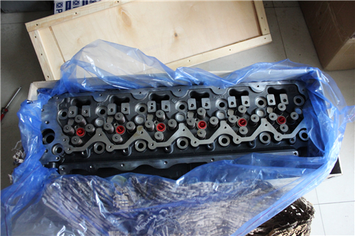
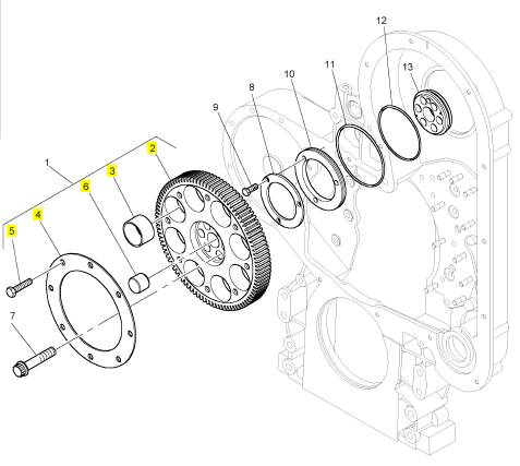
Perkins2306柴油发动机CH11153汽缸盖、气门、座圈、导管
详细描述
项目 零配件号码 新件号 描述
1 CH11153 1 CH11153 汽缸盖组合
1 CH11153 1 CH11153 汽缸盖组合
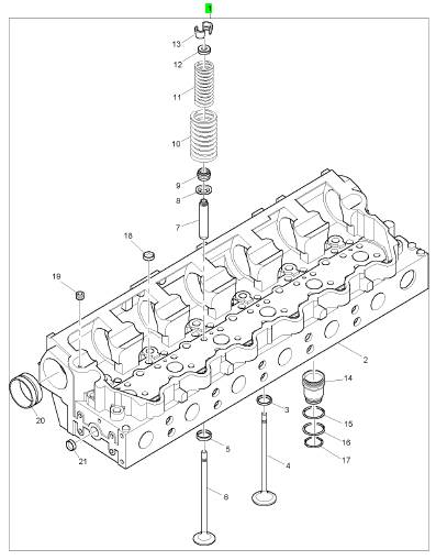
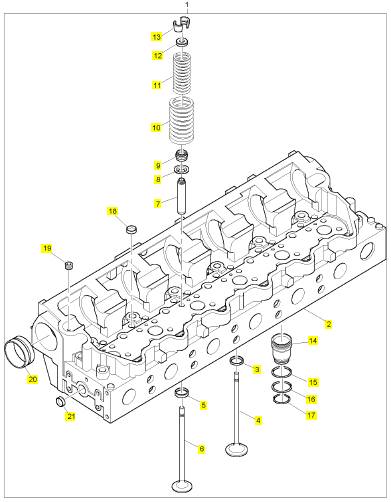
项目 零配件号码 新件号 描述
2 1 汽缸盖
3 CH10731 12 CH10731 气门座圈
4 CH11021 12 CH11021 进气门
5 CH10732 12 CH10732 气门座圈
6 CH11022 12 CH11022 排气阀
7 CH10724 24 CH10724 气门导管
8 CH10716 24 CH10716 垫圈
9 CH10717 24 CH11486 密封垫 - 阀转杆
10 CH10781 24 CH12798 阀弹簧外部的
11 CH10718 24 CH11489 阀弹簧内部
12 CH10715 24 CH10715 位子
13 CH10019 48 CH10019 阀筒夹
14 CH11311 6 CH11311 套筒
14 CH10728 6 CH11311 喷油器套筒
15 CH10726 6 CH10726 密封O型圈
16 CH10727 6 CH10727 密封O型圈
17 CH10723 6 CH10723 密封O型圈
18 CH10032 17 CH10032 栓塞
19 CH10258 3 CH10258 栓塞
20 CH11228 7 CH11228 凸轮轴衬套
21 CH10722 20 CH10722 栓塞
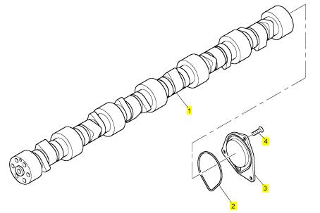
项目 零配件号码 新件号 描述
1 CH10964 1 CH10964 凸轮轴
1 CH10964 1 CH10964 凸轮轴
1 CH12778 1 CH12778 凸轮轴
2 CH10587 1 CH10587 密封O型圈
3 CH10588 1 CH10588 端盖
4 CH10589 3 CH10589 公制的螺旋
项目 零配件号码 新件号 描述
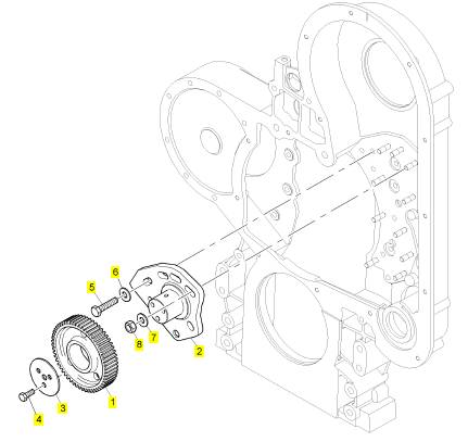
1 CH10635 1 CH10635 惰轮传动机构
2 CH10623 1 CH10623 螺木桩
3 CH10614 1 CH10614 推力板
4 CH10621 3 CH10621 螺拴
5 CH10609 1 CH10609 螺拴
6 CH10615 1 CH10615 垫圈
7 CH10615 5 CH10615 垫圈
8 CH10290 5 CH10798 螺帽
项目 零配件号码 新件号 描述
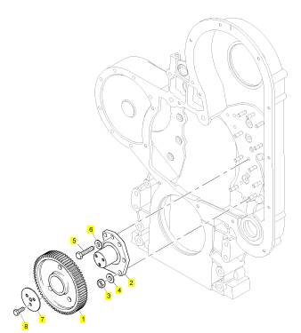
1 CH10632 1 CH10632 惰轮传动机构
2 CH10624 1 CH10624 螺木桩
3 CH10290 5 CH10798 螺帽
4 CH10615 5 CH10615 垫圈
5 CH10609 1 CH10609 螺拴
6 CH10615 1 CH10615 垫圈
7 CH10614 1 CH10614 推力板
8 CH10621 3 CH10621 螺拴
项目 零配件号码 新件号 描述
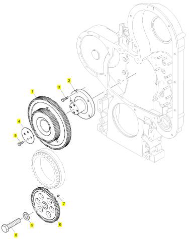
1 CH10963 1 CH10963 惰轮传动机构
2 CH10876 1 CH10876 螺木桩
3 CH10611 5 CH10611 螺拴
4 CH10619 1 CH10619 推力板
5 CH10621 4 CH10621 螺拴
6 CH10622 1 CH10622 油泵传动机构
7 CH10005 1 CH10005 半圆键
8 CH10609 1 CH10609 螺拴
9 CH10610 1 CH10610 垫圈
项目 零配件号码 新件号 描述
1 T400235 1 T400235 凸轮轴传动机构
7 CH10616 6 CH10616 螺拴
8 CH10617 1 CH10617 推力板
9 CH10618 3 CH10618 螺拴
10 CH10625 1 CH10625 密封垫
11 CH10620 1 CH10620 密封O型圈
12 CH10612 1 CH10612 密封O型圈
13 CH10627 1 CH10627 承接器
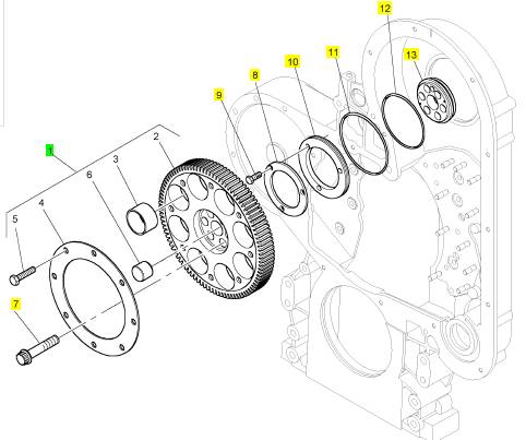
项目 零配件号码 新件号 描述
2 1 凸轮轴传动机构
3 8 滚子
4 1 保有板
5 CH10609 8 CH10609 螺拴
6 CH10641 1 CH10641 合钉
roubleshooting Section
KENR6224
Illustration 15
Connector for the pressure sensors
(1) Supply
(2) Return
(3) Signal
g01284861
Illustration 14
g01284898
C. Perform a 45 N (10 lb) pull test on each of the
wires that are associated with the pressure sensor
supply.
D. Check the allen head screw on each ECM
connector for the proper torque. Refer to the
Troubleshooting Guide, “Electrical Connectors -
Inspect” for the correct torque values.
E. Check the allen head screw on the customer
connector for the proper torque. Refer to the
Troubleshooting Guide, “Electrical Connectors -
Inspect” for the correct torque value.
F. Check the harness and the wiring for abrasion
and for pinch points from each sensor back to the
ECM.
Expected Result:
All of the connectors, pins and s ockets are completely
coupled and/or inserted and the harness and wiring
are free of corrosion, of abrasion and of pinch points.
Results:
• OK – The harness and connectors appear to be
OK. Proceed to Test Step 2.
P2 terminals that are associated with the 5 volt supply for the
pressure sensors
(P2-17) Return
(P2-72) +5 VDC
•
Not OK
OK.
– The c onnectors and/or wiring are not
Repair: Repair the wiring and/or the connectors.
Replace parts, if necessary. Ensure that all of the
seals are properly in place and ensure that the
connectors are completely coupled. Verify that the
repair eliminates the fault.
STOP.
This document has been printed from SPI². Not for Resale
![]() KENR6224
KENR6224
79
Troubleshooting Section
|
|
|
Codes
A. Connect the electronic service tool to the
diagnostic connector. Refer to the Troubleshooting
Guide, “Electronic Service Tools”.
B. Turn the keyswitch to the ON position.
C. Observe the “Active Diagnostic” screen on the
electronic service tool. Wait at least 15 seconds
so that any codes may become active. Look for
the following codes:
• 262-03
• 262-04
Expected Result:
One of the above codes is active.
Results:
Proceed to Test Step 3.
Proceed to Test Step 4.
active.
Repair: If any of the above codes are logged and
the engine is not running properly, refer to the
Troubleshooting Guide, “Troubleshooting Without
a Diagnostic Code”.
If the engine is running properly at this time, there
may be an intermittent fault in a harness that
is causing the codes to be logged. Refer to the
Troubleshooting Guide, “Electrical Connectors -
Inspect”.
STOP.
Test Step 3. Check the Voltage on the +5
V Supply Wire
A. Turn the keyswitch to the OFF position.
B. Disconnect the harness connectors for the
following sensors:
• Inlet manifold pressure sensor J200/P200
• Atmospheric pressure sensor J203/P203
• Engine oil pressure sens or J201/P201
C. Turn the keyswitch to the ON position.
|
following measurements in order to reveal an
intermittent fault.
D. Measure the voltage between terminals 1 and 2 at
each sensor connector on the engine harness.
Expected Result:
Each voltage measurement is 5.0 ± 0.2 VDC.
Results:
• OK – Each voltage measurement is 5.0 ± 0.2 VDC.
Repair: Connect all of the sensor connectors.
Clear all diagnostic codes. Check for active
diagnostic codes. If the fault is intermittent, refer to
the Troubleshooting Guide, “Elec trical Connectors
- Inspec t”.
STOP.
• Not OK – At least one voltage measurement is not
5.0 ± 0.2 VDC. There is a fault in the wiring or in
the ECM. Proceed to Test Step 5.
Sensors and Check for Active Diagnostic
Codes
A. Disconnect the following sensors one at a time:
• Inlet manifold pressure sensor J200/P200
• Atmospheric pressure sensor J203/P203
• Engine oil pressure sensor J201/P201
B. Wait for 15 seconds after you disconnect each
sensor. Check that the active 262-04 code is
deactivated.
Expected Result:
The 262-04 diagnostic code deactivates when a
particular sensor is disconnected.
Results:
• OK – The 262-04 diagnostic code deactivates
when a particular sensor is dis connected.
Repair: Connect the suspect sensor. If the code
returns, replace the sensor.
Connect all of the connectors. Verify that the fault
is cleared.
STOP.
This document has been printed from SPI². Not for Resale
![]() 80
80
Troubleshooting Section
KENR6224
•
Not OK
– The 262-04 diagnostic code remains
Note: Wiggle the harness during the following
|
|
|
the sensors disconnected. Proceed to Test Step 5.
Circuit
A. Turn the keyswitch to the OFF position.
B. Disconnect the P2 ECM connector. Disconnect
the P1 ECM connector.
C. Verify that all of the pressure sensors are
dis connected.
D. Measure the resistance between terminal P2-72
(+5 V Supply) and all of the other terminals on the
P2 connector.
E. Measure the resistance between terminal P2-72
and the engine ground.
F. Measure the resistance between terminal P1-2
(+5 V Supply) and all of the remaining terminals
on the P1 connector.
a. Measure the resistance between terminal P1-2
and the engine ground.
Expected Result:
Each resis tance measurement indicates an open
circuit.
Results:
• OK – Each resistance measurement indicates an
open circuit. Proceed to Tes t Step 6.
• Not OK – At least one of the resistance
measurements does not indicate an open circuit.
A +5 V supply wire has a fault. There may be a
fault in a connector.
Repair: Repair the wire and/or the connector,
when possible. Replace parts, if necess ary. Verify
that the fault is eliminated.
STOP.
the Sensor Common for an Open Circuit
A. Install a wire jumper between terminals P2-72 (+5
V Supply) and P2-17 (Sensor Return).
B. Install a wire jumper between terminals P1-2 (+5
V Supply) and P1-3 (Sensor Return).
measurements in order to reveal any intermittent
short condition.
C. Measure the resistance between terminals 1 and
2 at the harness connector for each pressure
sensor.
Expected Result:
Each resistance measurement is less than ten Ohms .
Results:
• OK – Each measurement is less than ten Ohms.
Proceed to Test Step 7.
• Not OK – At least one resistance measurement is
greater than ten Ohms. The +5 V supply wire or
the return wire has excessive resistance. There
may be a fault in a connector.
Repair: Repair the wire and/or the connector,
when possible. Replace parts, if necessary. Verify
that the fault is eliminated.
STOP.
Test Step 7. Check the +5 V Supply at the
ECM
A. Remove terminal 72 (+5 V Supply) from the
P2 connector. Install a wire jumper with socket
terminals on both ends into P2-72.
B. Connect ECM connectors J2/P2.
C. Remove terminal 2 (+5 V Supply) from the P1
connector. Install a wire jumper with socket
terminals on both ends into P1-2.
D. Connect ECM connectors J1/P1.
E. Turn the keyswitch to the ON position.
F. Measure the v oltage between the wire jumper in
P1-2 and the engine ground.
G. Measure the v oltage between the wire jumper in
P2-2 and the engine ground.
H. Turn the keyswitch to the OFF position.
I. Restore both wires to the original configuration.
Expected Result:
Both voltage measurements are 5.0 ± 0.2 VDC.
This document has been printed from SPI². Not for Resale
![]() KENR6224
KENR6224
81
Troubleshooting Section
Results:
• OK – Both voltage measurements are 5.0 ± 0.2
VDC.
Repair: Clear all diagnostic codes. Check for
active diagnostic codes. If the fault is intermittent,
refer to the Troubleshooting Guide, “Electric al
Connectors - Inspect”.
STOP.
• Not OK – At least one voltage measurement is
not 5.0 ± 0.2 VDC.
Repair: Replace the ECM. Refer to the
Troubleshooting Guide, “Replacing the ECM”.
STOP.
CAN Data
i02566204
Link Circuit - Test
System Operation Description:
The CAN data link is used to communicate
information between the Electronic Control Module
(ECM) and other modules. Use this procedure to
troubleshoot any suspected faults with the CAN data
link.
This procedure covers diagnostic code 0247-09.
This procedure identifies the following faults:
• Faulty connectors
• Missing termination resistors
• Short circuits
• Open circuits
• Faulty J1939 display
This document has been printed from SPI². Not for Resale
![]()
![]()
![]()
![]()
![]() 82
82
Troubleshooting Section
KENR6224
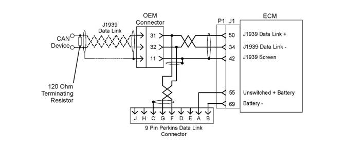
Illustration 16
Schematic for the CAN data link
Test Step 1. Inspect the
Electrical
g01285212
Connectors and the Wiring
A. Turn the keyswitch to the OFF position.
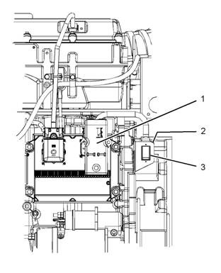
Illustration 17
Engine view (typic al example)
(1) P1 ECM connector
(2) Diagnostic connector
(3) OEM connector
g01285222
This document has been printed from SPI². Not for Resale
![]()
![]()
![]()
![]() KENR6224
KENR6224
83
Troubleshooting Section
B. Thoroughly ins pect connectors (1), (2), and (3).
Thoroughly inspect the connectors for each
module that is connected to the CAN data link.
Refer to the Troubleshooting Guide, “Electrical
Connectors - Inspect”.
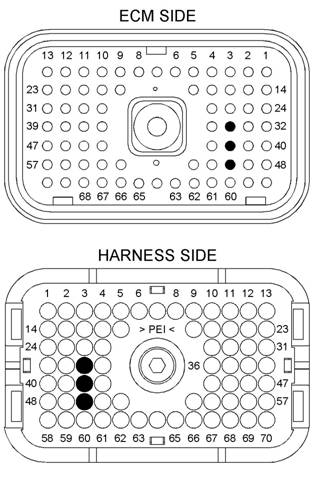
Illustration 19
g01285362
Illustration 18
P1 terminals that are associated with the CAN data link
(P1-34) CAN data link −
(P1-42) CAN shield
(P1-50) CAN data link +
g01215698
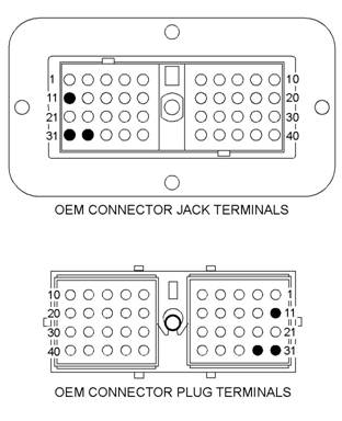
OEM connector terminals that are associated with the CAN data
link
(11) CAN shield
(31) CAN data link +
(32) CAN data link −
C. Perform a 45 N (10 lb) pull test on each of the
wires that are associated with the CAN data link.
D. Check the allen head screw on each ECM
connector for the proper torque. Refer to the
Troubleshooting Guide, “Electrical Connectors -
Inspect” for the correct torque values.
E. Check the allen head screw on the customer
connector for the proper torque. Refer to the
Troubleshooting Guide, “Electrical Connectors -
Inspect” for the correct torque value.
F. Check the wiring harnesses for abras ion, for
corrosion and for pinch points.
Expected Result:
All connectors, pins and sockets are completely
coupled and/or inserted. The harness and wiring are
free of corrosion, of abras ion and of pinch points.
Results:
• OK – The harness and the wiring appear to be
OK. Proceed to Test Step 2.
• Not OK – There is a fault in the wiring harness.
This document has been printed from SPI². Not for Resale
| |||||||||||||
Troubleshooting Section
KENR6224
|
Replace parts, if necessary. Ensure that all of the
seals are properly in place and ensure that the
connectors are completely coupled. Verify that the
fault is eliminated.
STOP.
Codes
A. Connect the elec tronic service tool to the
diagnostic connector. Refer to the Troubleshooting
Guide, “Electronic Service Tools”.
B. Turn the keyswitch to the ON position.
C. Observe the active diagnostic code screen on the
electronic service tool. Wait at least 15 seconds
•
•
Repair: Verify that two terminating resis tors exist
on the data link. One resistor must be located on
each end of the data link. If the optional harness is
ordered with the engine, the engine is shipped with
one terminating resistor that is installed between
the ECM and the customer connector.
Refer to the appropriate electrical schematic in
order to determine the missing resistor. Replace the
missing resistor. Verify that the fault is eliminated.
STOP.
Not OK – The resistance is less than 57 Ohms.
Proceed to Test Step 4.
Not OK – The resistance is greater than 126
Ohms. Proceed to Test Step 5.
|
Check for a 247-09 diagnostic code.
Expected Result:
No diagnostic codes are active.
Results:
• OK – No codes are active.
Repair: The fault may be intermittent. If the fault
is intermittent, refer to the Troubleshooting Guide,
“Electrical Connectors - Inspect”.
STOP.
Proceed to Test Step 3.
Test Step 3. Verify the Proper Installation
of t he CAN Data Link
A. Disconnect the J1939 display or the J1939 device.
B. Disconnect the P1 connector and measure the
resistance between terminals P1-50 (CAN data
link +) and P1-34 (CAN data link -).
Expected Result:
The resistance is between 57 and 63 Ohms.
Results:
• OK – The resistance is between 57 and 63 Ohms.
Proceed to Test Step 6.
• Not OK – The resistanc e is between 114 Ohms
and 126 Ohms. A terminating resis tor is missing.
Test Step 4. Check for a Short Circuit
A. Disconnect the P1 ECM connector.
B. Remove the terminating resistors from the CAN
data link.
C. If a J1939 display is installed, disconnect the
display.
D. Measure the resistance between the points that
are lis ted in Table 12. Be sure to wiggle the wires
in the harnesses as y ou make each resistance
measurement.
Table 12
Expected Result:
Each check of the resistance indicates an open
circuit.
Results:
• OK – Each check of the resistance indicates an
open circuit. Proceed to Test Step 5.
• Not OK – At least one check of the resistance does
not indicate an open circuit. There is a short circuit
in a harness. There may be a fault in a connector.
This document has been printed from SPI². Not for Resale
![]()
![]() KENR6224
KENR6224
85
Troubleshooting Section
Repair: Repair the wiring and/or the connector.
Replac e part, if necessary. Verify that the fault is
eliminated.
STOP.
Test Step 5. Check for an Open Circuit
A. Verify that all of the connections are disconnected.
B. Fabricate a jumper wire. Use the jumper wire in
order to create a short circuit between terminals G
and F on the diagnostic connector.
C. Measure the resistance between terminals P1-50
(CAN data link +) and P1-34 (CAN data link -).
D. Remove the jumper wire from the diagnostic
•
It is unlikely that the ECM has failed. Perform this
entire procedure again. Replace the ECM if the
display does not operate correctly. Refer to the
Troubleshooting Guide, “Replacing the ECM”.
STOP.
Not OK – The J1939 display does not operate
properly on another engine.
Repair: Replace the J1939 display. Verify that the
fault is eliminated.
STOP.
i02566846
connector.
Expected Result:
Data
Link Circuit - Test
The resistance is less than ten Ohms.
Results:
• OK – The resistance is less than ten Ohms. There
is not an open circuit. Proceed to Test Step 6.
• Not OK – The resistance is more than ten Ohms.
There is an open circuit or excessive resistance in
the circuit. There may be a fault in a connector.
Repair: Repair the wiring and/or the connector.
Replac e part, if necessary. Verify that the fault is
eliminated.
STOP.
Test Step 6. Check the J1939 Display
A. Connect the J1939 display to another engine.
B. Operate the engine and monitor the J1939 display.
Expected Result:
The J1939 display operates properly.
Results:
• OK – The J1939 display operates properly on
another engine.
Repair: Connect the display to the original engine.
If the display operates correctly, there may be
a fault in an electrical connector. Refer to the
Troubleshooting Guide, “Electrical Connectors -
Inspect”.
If the display does not operate c orrectly on the
original engine, there may be a fault in the ECM.
|
|
Note: This procedure checks for an open circuit
or for a short circuit in the Data Link. If you are
experiencing faults in communications between the
electronic service tool and the Electronic Control
Module (ECM), refer to the Troubleshooting Guide,
“Electronic Service Tool Will Not Communic ate with
ECM” before this procedure is used.
The Data Link is the standard data link that is used by
the ECM to communicate with the electronic service
tool. The ECM communicates with the electronic
service tool in order to share status information and
diagnos tic information. The electronic service tool can
also be used to configure the ECM parameters. This
information will not be available if communication fails
between the ECM and the electronic service tool.
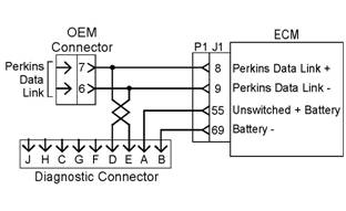
Illustration 20
Schematic for the Data Link
Connectors and the Wiring
A. Remove the electrical power from the ECM.
This document has been printed from SPI². Not for Resale