 English
 Espaol
 Franais
 阿拉伯
阿拉伯 中文
中文 Deutsch
 Italiano
 Português
 日本
日本 韩国
韩国 български
 hrvatski
 esky
esky Dansk
Dansk Nederlands
 suomi
suomi Ελληνικ
 印度
印度 norsk
norsk Polski
 Roman
Roman русский
 Svenska
Perkins2206D柴油发动机柴油发电机组配件销售供应商,Perkins2206D柴油发动机柴油发电机组配件销售技术价格规格咨询服务,Perkins2206D柴油发动机柴油发电机组配件销售零配件供应,Perkins2206D柴油发动机柴油发电机组配件销售售后服务中心,Perkins2206D柴油发动机柴油发电机组配件销售,Perkins2206D柴油发动机柴油发电机组配件销售详细的技术参数,

产品中心
Perkins2206D柴油发动机柴油发电机组配件销售
详细描述
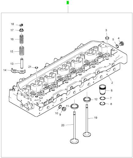
项目 零配件号码 新件号 描述
1 CH12455 1 CH12455 汽缸盖组合
(1) CH12455 1 CH12455 汽缸盖装备 -EXCH
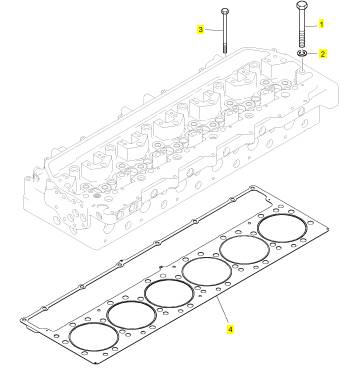
项目 零配件号码 新件号 描述
1 CH12569 26 CH12569 汽缸盖螺拴
2 CH12571 26 CH12571 垫圈
3 CH12570 8 CH12570 螺拴
4 CH12454 1 CH12454 密封垫 - 汽缸盖
项目 零配件号码 新件号 描述
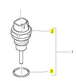
1 KRP1688 1 KRP1688 温度感应传感器
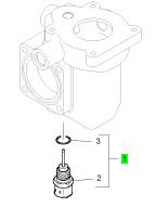
项目 零配件号码 新件号 描述
2 1 温度感应传感器
3 CH10146 1 CH10146 密封O型圈
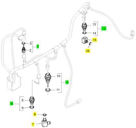
项目 零配件号码 新件号 描述
1 KRP1688 1 KRP1688 温度感应传感器
4 KRP1699 1 KRP1699 油压感应传感器装备
7 T401655 1 T401655 肘管
8 T409314 1 T409314 密封O型圈
9 KRP1687 1 KRP1687 温度感应传感器
12 KRP1693 1 KRP1693 气压感应传感器装备
15 CH12642 1 CH12642 承接器
16 CH11880 1 CH11880 密封O型圈
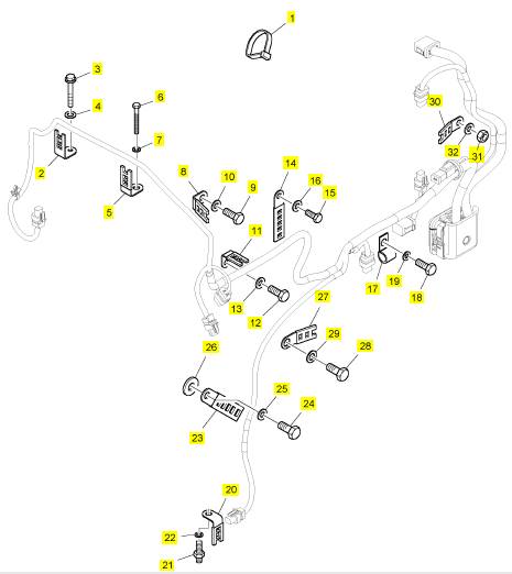
项目 零配件号码 新件号 描述
1 CH10054 13 CH10054 缆拉杆
2 T401576 2 T401576 接线夹
3 CH12286 2 CH12286 螺拴
4 CH10303 2 CH10303 垫圈
5 CH10420 1 CH10420 接线夹
6 CH11814 1 CH11814 公制的螺拴
7 CH10277 1 CH10277 垫圈
8 CH10072 1 CH10072 夹
9 CH12203 1 CH12203 螺拴
10 CH11819 1 CH11819 垫圈
11 CH10420 1 CH10420 接线夹
12 CH12203 1 CH12203 螺拴
13 CH11819 1 CH11819 垫圈
14 T401660 1 T401660 接线夹
15 CH12203 1 CH12203 螺拴
16 CH11819 1 CH11819 垫圈
17 T401662 1 T401662 接线夹
18 CH12203 1 CH12203 螺拴
19 CH11819 1 CH11819 垫圈
20 CH10420 1 CH10420 接线夹
21 CH12671 1 CH12671 图钉
22 CH10277 1 CH10277 垫圈
23 T401660 1 T401660 接线夹
24 CH11299 1 CH11299 螺拴
25 CH11819 1 CH11819 垫圈
26 T401297 1 T401297 垫圈
27 T401661 1 T401661 接线夹
28 CH10922 1 CH10922 螺拴
29 CH10099 1 CH10099 垫圈
30 T410794 1 T410794 接线夹
31 CH11865 1 CH11865 螺帽
32 CH11819 1 CH11819 垫圈
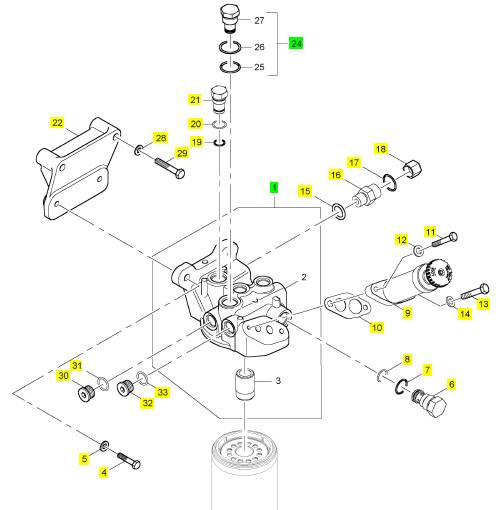
项目 零配件号码 新件号 描述
1 T401716 1 T401716 燃料过滤器
4 CH12612 2 CH12612 螺拴
5 CH11819 2 CH11819 垫圈
6 CH10836 1 CH10836 阀
7 T400188 1 T400188 密封O型圈
8 T400684 1 T400684 密封O型圈
9 CH10439 1 CH10439 汽酒共腾泵
10 CH10008 1 CH10008 密封垫
11 CH10246 1 CH10246 螺拴
12 CH10086 1 CH10086 垫圈
13 CH11565 1 CH11565 螺拴
14 T401636 1 T401636 垫圈
15 T408416 1 T408416 密封O型圈
16 T407241 1 T407241 连接器
17 CH11880 1 CH11880 密封O型圈
18 T409325 1 T409325 帽
19 T400857 1 T400857 密封O型圈
20 T400695 1 T400695 密封O型圈
21 T400694 1 T400694 栓塞
22 T401715 1 T401715 托架
23 T400188 1 T400188 密封O型圈
24 CH12017 1 CH12017 非回路阀
28 CH11819 2 CH11819 垫圈
29 ST43558 2 ST43558I 螺拴
30 CH10287 1 CH10287 栓塞
31 T406205 1 T406205 密封O型圈
32 CH10287 1 CH10287 栓塞
33 T406205 1 T406205 密封O型圈
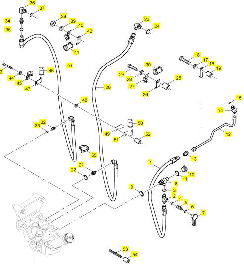
项目 零配件号码 新件号 描述
1 T401702 1 T401702 水管
2 T401708 1 T401708 承接器
3 CH11880 1 CH11880 密封O型圈
4 CH11880 1 CH11880 密封O型圈
5 CH11410 1 CH11410 栓塞
6 CH11880 1 CH11880 密封O型圈
7 CH11411 1 CH11411 灰尘盾
8 T401711 1 T401711 承接器
9 T406205 1 T406205 密封O型圈
10 CH10286 1 CH10286 栓塞
11 CH11880 1 CH11880 密封O型圈
12 T401717 1 T401717 管
13 T401704 1 T401704 承接器
14 T400646 1 T400646 承接器
15 CH11880 1 CH11880 密封O型圈
16 T401703 1 T401703 管夹
17 CH11819 1 CH11819 垫圈
18 CH11807 1 CH11807 螺拴
19 T401448 1 T401448 间隔器
20 T401714 1 T401714 水管
21 CH11595 1 CH11595 连接器
22 T406205 1 T406205 密封O型圈
23 CH10841 1 CH10841 连接
24 CH11880 1 CH11880 密封O型圈
25 T401448 1 T401448 间隔器
26 T400658 1 T400658 托架
27 T400659 1 T400659 托架
28 CH11819 1 CH11819 垫圈
29 CH11807 1 CH11807 螺拴
30 T400660 1 T400660 衬套
31 T401714 1 T401714 水管
32 CH10026 1 CH10026 连接
33 CH11880 1 CH11880 密封O型圈
34 CH10026 1 CH10026 连接
35 CH11880 1 CH11880 密封O型圈
36 T401713 1 T401713 肘管
37 CH10133 1 CH10133 密封O型圈
38 CH11865 1 CH11865 螺帽
39 CH11819 1 CH11819 垫圈
40 T400659 1 T400659 托架
41 T400660 1 T400660 衬套
42 T400658 1 T400658 托架
43 T401705 1 T401705 螺拴
44 CH10255 1 CH10255 垫圈
45 T400659 1 T400659 托架
46 T400660 1 T400660 衬套
47 T400658 1 T400658 托架
48 T401712 1 T401712 间隔器
49 T400658 1 T400658 托架
50 T400660 1 T400660 衬套
51 T400659 1 T400659 托架
52 T401707 1 T401707 间隔器
53 T401720 1 T401720 杆
54 T401706 1 T401706 间隔器
55 CH10054 2 CH10054 缆拉杆
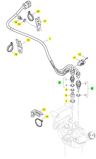
项目 零配件号码 新件号 描述
1 T401709 1 T401709 线束
2 KRP1699 1 KRP1699 油压感应传感器装备
5 T409314 1 T409314 密封O型圈
6 T400689 1 T400689 承接器
7 T406205 1 T406205 密封O型圈
8 KRP1687 1 KRP1687 温度感应传感器
11 28170044 1 28170044 电力有关连接器
12 2900 A011 2 2900 A011 销
13 CH10420 1 CH10420 接线夹
14 CH10054 1 CH10054 缆拉杆
15 T410794 1 T410794 接线夹
16 CH10054 1 CH10054 缆拉杆
17 T410794 1 T410794 接线夹
18 CH12203 1 CH12203 螺拴
19 CH11819 1 CH11819 垫圈
20 CH10054 1 CH10054 缆拉杆
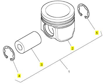
项目 零配件号码 新件号 描述
1 T401573 6 T401573 活塞装备
6 T401572 6 T401572 活塞环装备
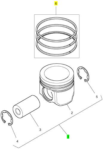
项目 零配件号码 新件号 描述
2 1 活塞
3 CH12332 1 CH12332 轴头销
4 CH12331 1 CH12331 CIRCLIP
5 CH12331 1 CH12331 CIRCLIP
项目 零配件号码 新件号 描述
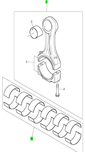
1 CH12635 6 CH12635 连杆组合
5 KRP3023 1 KRP3023 大头轴承装备
(5) KRP3023/051 1 KRP3023/051 大头 BRG 装备 -U/S
(5) KRP3023/076 1 KRP3023/076 大头 BRG 装备 -U/S
项目 零配件号码 新件号 描述
1 CH12334 6 CH12334 活塞冷却喷咀
2 CH10239 6 CH10239 螺拴
3 CH10255 6 CH10255 垫圈
项目 零配件号码 新件号 描述
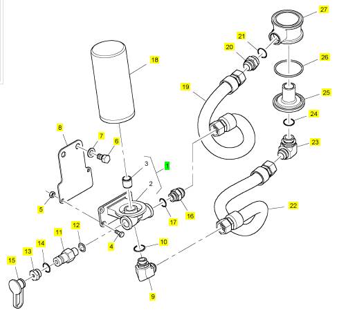
1 T401692 1 T401692 燃油滤清器
4 CH11299 2 CH11299 螺拴
5 CH11865 2 CH11865 螺帽
6 T401694 2 T401694 螺拴
7 T401001 2 T401001 垫圈
8 T401700 1 T401700 板
9 T401696 1 T401696 承接器
10 T400544 1 T400544 密封O型圈
11 CH10822 1 CH10822 工具
12 T409314 1 T409314 密封O型圈
13 T401693 1 T401693 承接器
14 T400544 1 T400544 密封O型圈
15 2658 A101 1 2658 A101 帽
16 T401697 1 T401697 承接器
17 T400544 1 T400544 密封O型圈
18 4587260 1 4587260 滤油器
19 T401695 1 T401695 水管 -油
20 T401698 1 T401698 承接器
21 T400762 1 T400762 密封O型圈
22 T401695 1 T401695 水管 -油
23 T401699 1 T401699 承接器
24 T400762 1 T400762 密封O型圈
25 T401691 1 T401691 盖
26 T401690 2 T401690 密封O型圈
27 T401689 1 T401689 承接器
项目 零配件号码 新件号 描述
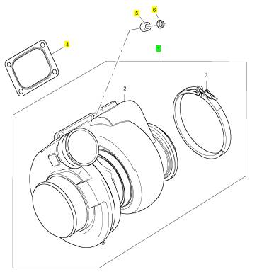
1 T401657 1 T401657 涡轮增压器
4 T401656 1 T401656 密封垫
5 T401658 4 T401658 间隔器
6 CH11242 4 CH11242 锁紧螺母
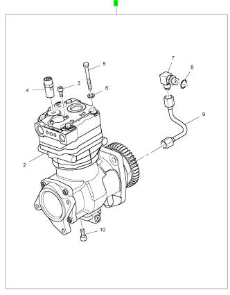
项目 零配件号码 新件号 描述
1 T400315 1 T400315 压缩机
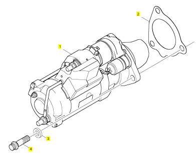
项目 零配件号码 新件号 描述
1 T400318 1 T400318 启动马达
2 CH10310 1 CH10310 密封垫
3 T400724 3 T400724 垫圈
4 T400720 3 T400720 螺拴
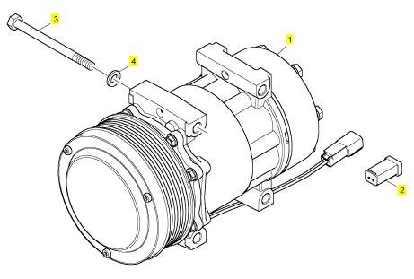
项目 零配件号码 新件号 描述
1 2488 A298 1 2488 A298 压缩机
2 T401634 1 T401634 栓塞
3 T401635 4 T401635 螺拴
4 T401636 4 T401636 垫圈
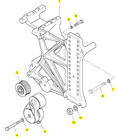
项目 零配件号码 新件号 描述
1 T401628 1 T401628 托架
2 T401626 1 T401626 惰轮皮带轮
3 T401627 1 T401627 紧张
4 T401629 1 T401629 螺拴
5 T405615 1 T405615 垫圈
6 CH11777 2 CH11777 螺拴
7 CH10099 2 CH10099 垫圈
8 CH12447 2 CH12447 螺拴
9 CH10277 2 CH10277 垫圈
10 317013 2 317013 螺帽
11 CH10099 2 CH10099 垫圈
项目 零配件号码 新件号 描述
1 T400313 1 T400313 交流充电发电机
2 T401641 1 T401641 皮带轮
3 T401642 4 T401642 螺拴
4 T407566 4 T407566 垫圈
项目 零配件号码 新件号 描述
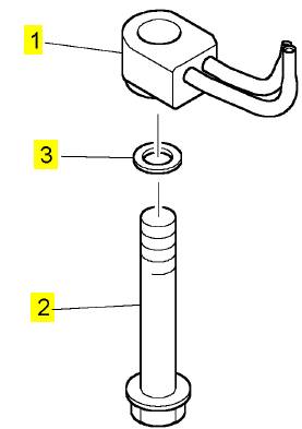
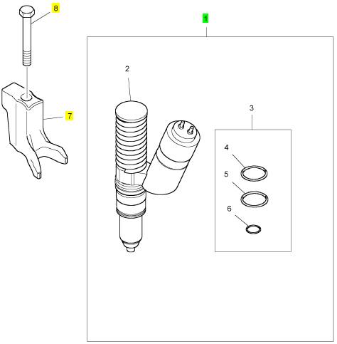
1 T401643 6 T401643 喷油器
(1) T401643R 6 T401643R 喷油器
7 CH12324 6 CH12324 喷油器摇臂座
8 CH12326 6 CH12326 螺拴
|
|
|
replace the connectors or wiring. Ensure that all of
the seals are properly in place and ensure that the
connectors are completely coupled.
Verify that the repair eliminates the fault.
STOP.
Test Step 2. Check the Supply Voltage at
the Sensor Connector
A. Turn the keyswitch to the OFF position.
B. Disconnect all of the following analog sensors at
the sensor connector:
•
• Inlet manifold pressure sensor
• Atmospheric pressure sensor
C. Turn the keyswitch to the ON position.
D. Measure the voltage between terminal 1 (5 V
analog supply) and terminal 2 (sensor return) at
each of the sensor connectors.
E. Turn the keyswitch to the OFF position.
F. Reconnect all of the sensors.
Expected Result:
The voltage is 5.0 ± 0.16 VDC.
Results:
is correct. Proceed to Test Step 3.
voltage is incorrect.
Repair: Perform the diagnostic functional test
in the Troubleshooting Guide, “5 Volt Engine
Pressure Sensor Supply Circuit - Test”.
STOP.
Test Step 3. Check for Active Diagnostic
Codes
A. Connect the elec tronic service tool to the
diagnostic connector.
B. Turn the keyswitch to the ON position.
C. Monitor the active diagnostic code screen on the
electronic service tool. Check and record any
active diagnostic codes.
|
|
diagnostic codes to bec ome activ e.
D. Determine if the fault is related to an open circuit
diagnostic code 03 or a short circuit diagnostic
code 04.
Expected Result:
No diagnostic codes are active.
Results:
• OK – No diagnostic codes are active.
Repair: The fault may have been related to
a faulty connection in the harness. Carefully
reinspect the connectors and wiring. Refer to the
Troubleshooting Guide, “Electrical Connectors -
Inspect”.
STOP.
• Not OK – A short circuit diagnostic c ode (04) is
active at this time. Proceed to Test Step 4.
• Not OK – An open circuit diagnostic code (03) is
active at this time. Proceed to Test Step 5.
Sensor in Order to Create an Open Circuit
A. Turn the keyswitch to the OFF position.
B. Disconnect the sensor connector of the sensor
with the short circuit diagnostic code (04).
C. Turn the keyswitch to the ON pos ition. Wait at
least 15 seconds for activation of the diagnostic
codes.
D. Access the “Active Diagnostic Code” screen on
the electronic service tool. Check for an active
open circuit diagnostic code (03).
E. Turn the keyswitch to the OFF position.
Expected Result:
An open circuit diagnostic code 03 is now active for
the disconnected sensor.
Results:
active before disconnecting the sensor. An open
circuit diagnostic code (03) became active after
disconnecting the sensor.
This document has been printed from SPI². Not for Resale
![]() 102
102
Troubleshooting Section
KENR6224
•
Repair: Temporarily connect a new sensor to the
harness, but do not install the new sensor in the
engine. Verify that there are no active diagnostic
codes for the sensor. If there are no active
diagnostic codes for the sensor, permanently
install the new sensor. Clear any logged diagnostic
codes.
STOP.
Not OK – There is a short circuit between the
sensor harness connector and the ECM. Leave the
sensor disconnected. Proceed to Test Step 8.
E. Measure the resistance between the terminal for
the sensor signal wire at the ECM and engine
ground.
F. Rec onnect P1 and P2.
Expected Result:
Each resistance measurement is greater than 20,000
Ohms.
Results:
• OK – Each of the resistance measurements is
|
A. Turn the keyswitch to the ON position.
B. Disconnect the suspect sensor.
C. Measure the voltage between terminal 3 (signal)
and terminal 2 (sensor return) at the sensor
connector.
D. Turn the keyswitch to the OFF position.
•
greater than 20,000 Ohms. Proceed to Test Step 7.
Not OK – At least one resistance measurement is
less than 20,000 Ohms.
Repair: The low resistance measurement indicates
a low resistance between two or more wires.
Repair the connectors or wiring and/or replace the
connectors or wiring.
STOP.
|
|
The voltage is 11 ± 2 VDC.
Results:
to the ECM from the sensor connector is OK.
Repair: The open circuit is in the sensor o, r the
wire between the sensor and the sensor connector.
Replac e the sensor. Do not install the sensor in
the engine. Verify that no diagnostic codes are
active for the sus pect sensor before permanently
installing the s ensor.
STOP.
voltage is incorrect. Proceed to Test Step 6.
Test Step 6. Check the Signal Wire for a
Short Circuit
A. Turn the keyswitch to the OFF position.
B. Disconnect ECM connectors P1 and P2.
C. Disconnect the connector for the suspect sensor.
D. Measure the resistance between the terminal
for the sensor signal wire at the ECM and
every terminal on ECM connector P1 and ECM
connector P2.
|
A. Turn the keyswitch to the OFF position.
B. Install a jumper wire with Ampseal sockets on
each end between terminal 2 (sensor return) and
terminal 3 (signal) on the connector for the suspec t
sensor. Connect the jumper on the harness side
of the connector.
C. Turn the keyswitch to the ON position.
D. Wait at least 15 seconds for activ ation of the short
circuit diagnostic code 04.
Note: Monitor the “Active Diagnostic Codes” screen
on the electronic service tool before installing the
jumper wire and after installing the jumper wire.
E. Remove the jumper wire.
F. Turn the keyswitch to the OFF position.
Expected Result:
A short circuit diagnostic code 04 is active when the
jumper wire is installed. An open circuit diagnostic
code 03 is activ e when the jumper wire is removed.
Results:
• OK – The engine harness and the ECM are OK.
This document has been printed from SPI². Not for Resale
![]() KENR6224
KENR6224
103
Troubleshooting Section
•
Repair: Temporarily connect a new sensor to the
harness, but do not install the new sensor in the
engine. Verify that there are no active diagnostic
codes for the sensor. If there are no active
diagnostic codes for the sensor, permanently
install the new sensor. Clear any logged diagnostic
codes.
STOP.
Not OK – The open circuit diagnostic code 03
remains active with the jumper in place. The
open circuit is between the ECM and the sensor
connector. Proceed to Test Step 8.
Expected Result:
An open circuit diagnostic code 03 is active when
the sensor signal wire is removed from the ECM
connector. A short circuit diagnostic c ode 04 is active
when the signal wire is connected to the sensor
return.
Results:
• OK – The ECM is operating properly. The fault is
in the wiring between the ECM and the sensor
connector.
Repair: If the code is active for more than one
|
A. Turn the keyswitch to the OFF position.
B. Check the operation of the ECM by creating an
open circuit at the ECM.
a. Remove the signal wire for the suspect sensor
from the P2 ECM connector.
b. Remove the sensor return for the s uspect
sensor from the P2 ECM connector.
Note: Disconnecting the sensor return from the ECM
will generate an open circuit diagnostic code for all
sensors that are connected to the sensor return.
Troubleshoot the original diagnostic code. Delete the
logged diagnostic codes when you are finished.
c. Reconnect the ECM connector.
d. Turn the keyswitch to the ON position. Monitor
the “Active Diagnostic Code” screen on the
electronic service tool. Wait at least 15 seconds
•
sens or, the fault is most likely in the return wire for
the sensor. Repair the return wire for the sensor
or replace the harness.
If the c ode is only active for one sensor, the fault is
most likely in the signal wire for the sensor. Repair
the signal wire for the sensor.
STOP.
Not OK – One of the following conditions exists:
The open circuit diagnostic code 03 is not active
when the sensor signal wire is disconnected. The
short c ircuit diagnostic code 04 is not active when
the wire jumper is installed.
Repair: Replace the ECM. Refer to the
Troubleshooting Guide, “Replacing the ECM”.
Verify that the fault is eliminated.
STOP.
i02569903
for activation of the code.
Engine
Speed/Timing Sensor
An open circuit diagnostic code (03) should be
active for the suspect sensor.
C. Check the operation of the ECM by creating a
short at the ECM.
a. Install a wire jumper between the two terminals
for the sensor signal and the sensor return.
b. Reconnect the ECM connector.
c. Monitor the “Active Diagnostic Code” screen
on the electronic serv ice tool. Wait at least 15
seconds for activation of the code.
A short circuit diagnostic code (04) should be
active when the wire jumper is installed.
d. Remove the wire jumper and reconnect all
wires.
Circuit - Test
System Operation Description:
Use this procedure to troubleshoot any suspect faults
with the following sensors:
• Crankshaft position sensor
• Cams haft position sensor
This procedure covers the following open circuit
diagnostic codes and short circuit diagnostic codes:
• 190-02 Engine Speed Sensor erratic, intermittent
or incorrect
• 190-09 Engine Speed Sensor abnormal update
rate
This document has been printed from SPI². Not for Resale
![]() 104
104
Troubleshooting Section
KENR6224
•
•
•
•
•
190-11 Engine Speed Sensor mechanical failure
190-12 Engine Speed Sensor failure
342-02 Secondary Engine Speed Sensor erratic,
intermittent or incorrect
342-11 Secondary Engine Speed Sensor other
failure mode
342-12 Secondary Engine Speed Sensor failure
Both sensors are magnetic sensors. The two sensors
are not interchangeable. Do not switch the positions
of the sensor. If the sensors are replaced, a timing
calibration is not necessary.
If a replacement of the ECM is required, the ECM
parameters and the timing calibration can be
transferred from the suspect ECM to the replacement
ECM. Timing calibration will not be necessary. This
feature requires the electronic servic e tool and this
feature is only possible if the existing ECM can
communicate with the electronic service tool. Use the
The engine uses 2 position sensors. The cranks haft
position sensor detects the unique pattern of the
crankshaft gear and the cams haft position sensor
picks up the unique pattern of the camshaft gear.
Both of the position sensors detect the reference for
engine speed and timing from a unique pattern on the
gear. The Engine Control Module (ECM) measures
the time between the pulses that are created by the
sensors as the gears rotate in order to determine rpm.
Under normal operation, the camshaft position sensor
is used to determine timing for starting purposes.
The camshaft position sensor is used to determine
when the piston in the No. 1 cylinder is at the top of
the compression stroke. When the timing has been
established, the crankshaft position sensor is then
used to determine engine speed.
After locating the No. 1 cy linder, the ECM triggers
each electronic unit injector in the correct firing order
and at the correct timing. The actual timing and
duration of each injection is based on engine rpm
and load. If the engine is running and the signal from
the crankshaft position sensor is lost, a slight change
in engine performanc e will be noticed when the ECM
performs the changeover to the camshaft position
sensor. Loss of the signal from the camshaft position
sensor during engine operation will not result in any
noticeable change in engine performance. However,
if the signal from the camshaft position sensor is not
present during start-up the following conditions may
exist:
• The engine may require a slightly longer period
of time to s tart-up.
• The engine may run rough for a few seconds until
the ECM determines the proper firing order with
the crankshaft position sensor.
The engine will start and the engine will run when only
one sensor signal is present. The loss of the signal
from both of the sens ors during engine operation will
result in the termination of injection and the shutting
down the engine by the ECM. The loss of the signal
from both of the sensors during start-up will prevent
the engine from starting.
“Copy Configuration - ECM Replacement” feature on
the electronic service tool.
Complete all of the following tasks when you
install a position sensor:
• Lubricate the O-ring with oil.
• Ensure that the sensor has a face seal inside the
connector body. If a seal is damaged or missing,
replace the s eal.
• Ensure that the s ensor is fully seated into the
engine before tightening the bracket bolt.
• Ensure that the connector is latched on both sides.
• Ensure that the harness is properly secured, and
ensure that the tie-wraps are placed in the correct
location.
This document has been printed from SPI². Not for Resale
![]()
![]() KENR6224
KENR6224
105
Troubleshooting Section
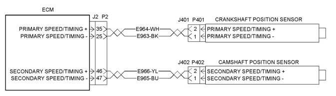
Illustration 40
Schematic for position s ensors
g01287361
This document has been printed from SPI². Not for Resale
![]()
![]() 106
106
Troubleshooting Section
KENR6224
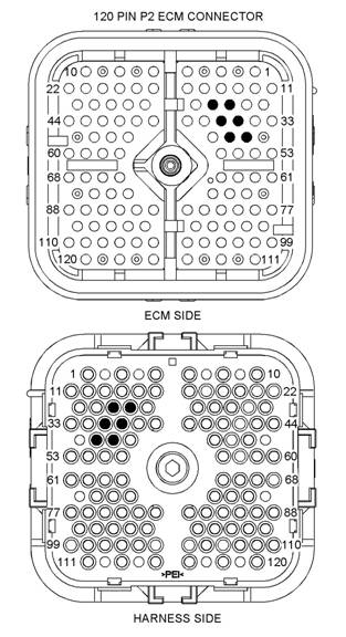
Illustration 41
P2 ECM connector
(P2-25) Primary engine speed/timing −
(P2-26) TDC probe +
(P2-35) Primary engine speed/timing +
(P2-36) TDC probe −
(P2-46) Secondary engine speed/timing +
(P2-47) Secondary engine speed/timing −
g01099116
|
rpm on the electronic service tool while the engine is
being cranked. The electronic service tool may need
to be powered from another battery while the engine
is being c ranked.
D. Check for one of the following logged diagnostic
codes or active diagnostic codes:
• 190-02
• 190-09
• 190-11
• 190-12
• 342-02
• 342-11
• 342-12
Expected Result:
One of the diagnostic codes that are listed above are
logged or active.
Note: If the engine will not start and the electronic
service tool displayed 0 rpm during cranking, selec t
“No Engine rpm”.
Results:
• 190-XX or 342-XX – There is an active diagnostic
code or a logged diagnostic code. Proceed to Test
Step 3.
• Not OK – Refer to “Troubleshooting Without a
Diagnostic Code” if the following conditions exist:
The codes are not active. The codes are not
logged. The engine is not running properly. STOP.
• No Engine rpm – Engine rpm is not indicated on
the electronic service tool. Proceed to Test Step 2.
Sensors
A. Turn the keyswitch to the OFF position.
Test Step 1. Check for Diagnostic Codes
A. Connect the electronic service tool to the
diagnostic connector.
B. Turn the keyswitch to the ON position.
C. Start the engine and run the engine until the
engine is at normal operating temperature.
This document has been printed from SPI². Not for Resale
![]()
![]() KENR6224
KENR6224
107
Troubleshooting Section
5.
Ensure that the harness is properly secured,
and ensure that the tie-wraps are placed in the
correct location.
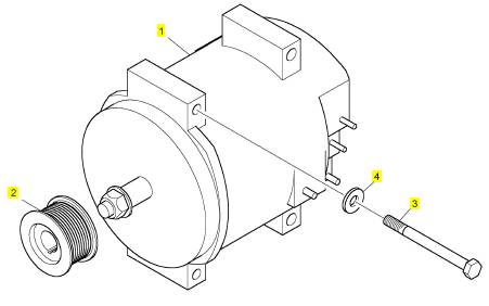
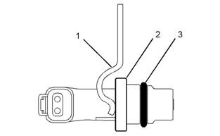
Illustration 42
Typical speed sensor
g01146452
•
Proceed to Test Step 3.
Not OK – At least one of the components of the
sens or is not OK.
Repair: Obtain a new sensor. Perform the following
procedure in order to properly install the new
sens or:
1. Lubricate the O-ring with engine oil.
2. Fully seat the sensor in the engine.
(1) Bracket
(2) Flange
(1) O-ring
B. Vis ually inspect the sensor without removing the
sensor from the engine. Flange (2) must be flush
against the engine in order to ensure proper
operation. Inspect bracket (1) in order to ensure
that the installation allows the flange of the sensor
to be flush against the engine. Verify that the
bracket is not bent.
Note: The bracket cannot be replaced separately.
C. Remove the sensor. Ensure that one O-ring (3)
is installed on the sensor. Check the O-ring for
damage. Replace the O-ring, if necessary.
Expected Result:
The components of the sensor are OK.
Results:
• OK – The components of the sensor are OK.
Repair: Perform the following procedure in order
to properly install the sensor:
1. Lubricate the O-ring with engine oil.
2. Fully seat the sensor in the engine.
Note: If the sensor will not fully seat into the engine,
replace the sensor.
3. Tighten the bracket bolt.
4. Connect the electrical connector to the sensor.
Verify that the connector is latched on both
sides.
|
replace the sensor.
3. Tighten the bracket bolt.
4. Connect the electrical connector to the sensor.
Verify that the connector is latched on both
sides.
5. Ensure that the harness is properly secured,
and ensure that the tie-wraps are placed in the
correct location.
Verify that the repair eliminates the fault.
STOP.
Resistance through the Engine Harness
A. Turn the keyswitch to the OFF position.
B. Thoroughly inspect the J2/P2 ECM connector.
Refer to the Troubleshooting Guide, “Electrical
Connectors - Inspect” for details.
C. Perform a 45 N (10 lb) pull test on the wires that
are associated with the position sensors .
D. Ensure that the latch tab on each sensor
connector is properly latched.
E. Check the allen head screw on each ECM
connector for the proper torque. Refer to the
Troubleshooting Guide, “Electrical Connectors -
Inspect” for the correct torque values.
F. Repair the harness or repair the connector if a
fault is found.
G. Ensure that the wiring harness is correctly routed
and secured at the correct locations.
This document has been printed from SPI². Not for Resale
![]() 108
108
Troubleshooting Section
KENR6224
H. Ensure that the harness wiring is not pulled
too tightly. When the harness wiring is pulled
too tightly, vibrations or movement can cause
intermittent connections.
I. Inspect the harness wiring for nicks and abrasions.
J. If the harness and the connector are OK,
dis connect the J2/P2 ECM connector.
K. If you are troubleshooting a fault with the
crankshaft position sensor, perform the following
procedure:
a. Measure the sens or resistance between P2-35
(Primary engine speed/timing positive) and
P2-25 (Primary engine speed/timing negative).
b. Check for an intermittent open circuit or for a
short circuit by moving the harness while you
take the resistance measurement. Pull the
wires that are directly behind the sensor or
shake the wires that are directly behind the
sensor.
Resistance ............................ 75 to 230 Ohms
L. If you are troubleshooting a fault with the camshaft
position sensor, perform the following procedure:
a. Measure the sens or resistance between P2-46
(Secondary engine speed/timing positive)
and P2-47 (Secondary engine speed/timing
negative).
b. Check for an intermittent open circuit or for a
short circuit by moving the harness while you
take the resistance measurement. Pull the
wires that are directly behind the sensor or
shake the wires that are directly behind the
sensor.
Resistance ........................ 600 to 1800 Ohms
Expected Result:
The readings are within the spec ifications.
Results:
• OK – The readings are within the specifications.
Neither a short circuit nor an open circuit is
indicated. Proceed to Test Step 5.
• Not OK – The readings are not within the
specifications. The sensor resistance is not within
the acceptable range when the sensor resistance
is measured through the engine harness. Proceed
to Test Step 4.
|
|
|
A. Disconnect the suspect sensor from the engine
harness.
B. Thoroughly inspect the sensor connectors.
Refer to the Troubleshooting Guide, “Electrical
Connectors - Inspect” for details.
C. If you are troubleshooting a fault with the
crankshaft position sensor, perform the following
procedure:
a. Measure the sensor resistance between J401-2
(Primary engine speed/timing positive) and
J401-1 (Primary engine speed/timing negative).
Resistance ............................. 75 to 230 Ohms
D. If you are troubleshooting a fault with the camshaft
position sensor, perform the following procedure:
a. Measure the sensor resistance between J402-2
(Secondary engine speed/timing positive)
and J402-1 (Secondary engine speed/timing
negative).
Resistance ........................ 600 to 1800 Ohms
Expected Result:
The readings are within the specifications.
Results:
Proceed to Test Step 5.
spec ifications.
Repair: Perform the following procedure in order
to check and install the new sensor:
1. Before you install the new sensor, measure the
resistance of the new sensor.
If the new sensor resistance is within the
specification, install the new sensor in the
engine according to the following procedure:
a. Loosen the bolt and remove the bolt that
holds the sensor mounting bracket to the
engine.
b. Ensure that one O-ring is installed on the
new sensor. Verify that the O-ring is free of
damage.
c. Lubricate the O-ring.
This document has been printed from SPI². Not for Resale