 English
 Espaol
 Franais
 阿拉伯
阿拉伯 中文
中文 Deutsch
 Italiano
 Português
 日本
日本 韩国
韩国 български
 hrvatski
 esky
esky Dansk
Dansk Nederlands
 suomi
suomi Ελληνικ
 印度
印度 norsk
norsk Polski
 Roman
Roman русский
 Svenska
Perkins2206D柴油发动机配件供应商,Perkins2206D柴油发动机配件技术价格规格咨询服务,Perkins2206D柴油发动机配件零配件供应,Perkins2206D柴油发动机配件售后服务中心,Perkins2206D柴油发动机配件,Perkins2206D柴油发动机配件详细的技术参数,

产品中心

Perkins2206D柴油发动机配件
详细描述
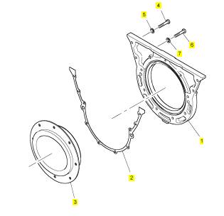
项目 零配件号码 新件号 描述
1 CH12108 1 CH12108 盖
2 CH10166 1 CH10166 密封垫
3 T401032 1 T401032 密封垫
4 CH12110 7 CH12110 螺拴
5 CH10086 7 CH10086 垫圈
6 CH10246 6 CH10246 螺拴
7 CH10086 6 CH10086 垫圈
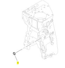
项目 零配件号码 新件号 描述
1 CH10032 1 CH10032 栓塞
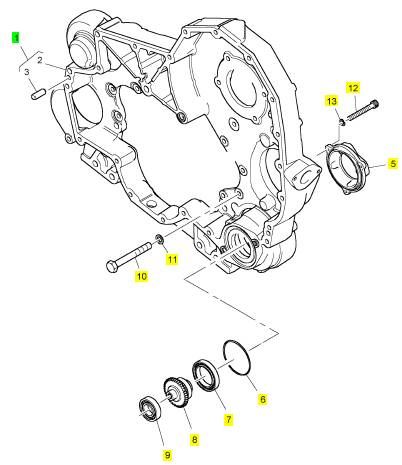
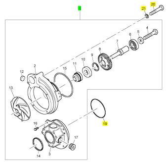
项目 零配件号码 新件号 描述
1 CH12443 1 CH12443 壳
4 CH12445 1 CH12445 密封垫 - 正时齿轮箱
5 CH12444 1 CH12444 盖
6 CH10620 1 CH10620 密封O型圈
7 CH12439 1 CH12439 滚珠轴承
8 CH12440 1 CH12440 附加的传动机构
9 CH12382 1 CH12382 滚珠轴承
10 CH12449 9 CH12449 螺拴
11 CH10277 9 CH10277 垫圈
12 CH12448 3 CH12448 螺拴
13 CH10277 3 CH10277 垫圈
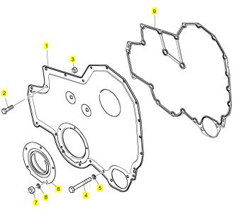
项目 零配件号码 新件号 描述
1 CH12446 1 CH12446 盖
2 CH10041 1 CH10041 螺拴
3 CH12450 1 CH12450 螺帽
4 CH12447 17 CH12447 螺拴
5 CH10277 17 CH10277 垫圈
6 CH12442 1 CH12442 密封垫 -油
7 CH12450 4 CH12450 螺帽
8 CH12452 4 CH12452 垫圈
9 CH12441 1 CH12441 密封垫 - 正时齿轮箱盖
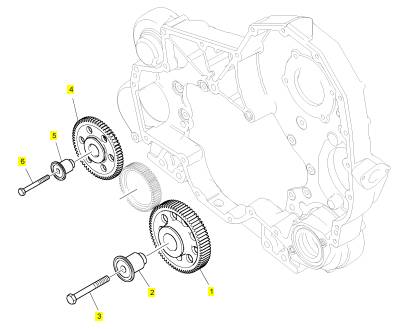
项目 零配件号码 新件号 描述
1 CH12291 1 CH12291 惰轮传动机构
2 CH12289 1 CH12289 轴
3 CH12293 1 CH12293 螺拴
4 CH12290 1 CH12290 传动机构
5 CH10181 1 CH10181 轴
6 CH10243 1 CH10243 螺拴
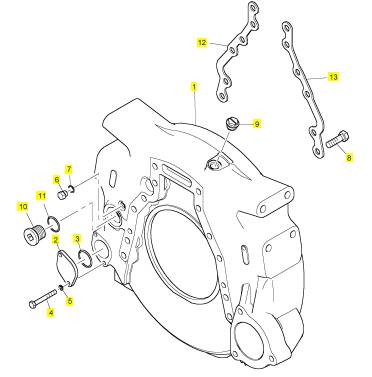
项目 零配件号码 新件号 描述
1 CH12535 1 CH12535 飞轮壳
2 CH10165 1 CH10165 盖
3 CH11892 1 CH11892 密封O型圈
4 CH12449 2 CH12449 螺拴
5 CH10277 2 CH10277 垫圈
6 T400249 1 T400249 栓塞
7 T409315 1 T409315 密封O型圈
8 CH12151 12 CH12151 螺拴
9 T401037 3 T401037 栓塞
10 CH10291 1 CH10291 栓塞
11 T400544 1 T400544 密封O型圈
12 CH12536 1 CH12536 间隔器
13 CH12536 1 CH12536 间隔器
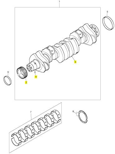
项目 零配件号码 新件号 描述
1 CH12736 1 CH12736 曲轴组合
5 CH12496 1 CH12496 套筒
6 CH12497 1 CH12497 套筒
7 KRP3120 1 KRP3120 曲轴瓦
(7) KRP3120/051 1 KRP3120/051 曲轴瓦 -U/S
8 KRP3207 1 KRP3207 止推片
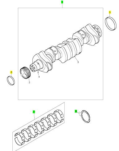
项目 零配件号码 新件号 描述
2 CH12493 1 CH12493 曲轴传动机构
3 1 曲轴
4 CH12495 1 CH12495 合钉 装备
项目 零配件号码 新件号 描述
1 KRP1721 1 KRP1721 提升泵
4 CH10436 2 CH10436 螺拴
5 CH10255 2 CH10255 垫圈
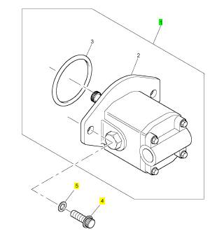
项目 零配件号码 新件号 描述
1 CH12887 1 CH12887 水泵
(1) CH12887 1 CH12887 水泵
19 CH10147 1 CH10147 密封O型圈
20 CH10248 2 CH10248 螺拴
21 CH11819 2 CH11819 垫圈
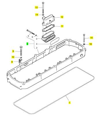
项目 零配件号码 新件号 描述
1 T400395 1 T400395 阀盖
7 CH12459 1 CH12459 密封垫 - 摇臂室
8 CH10420 1 CH10420 接线夹
9 CH11814 7 CH11814 公制的螺拴
10 CH10277 7 CH10277 垫圈
11 CH12457 2 CH12457 密封垫 -呼吸者
12 T401637 1 T401637 呼吸者
13 CH12629 4 CH12629 螺拴
14 CH10303 4 CH10303 垫圈
15 CH10140 6 CH10140 螺拴
16 CH10277 6 CH10277 垫圈
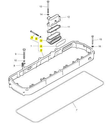
项目 零配件号码 新件号 描述
2 1 阀盖
3 T417055 1 T417055 承接器
4 T400396 1 T400396 密封O型圈
5 T400397 2 T400397 螺拴
6 CH10277 2 CH10277 垫圈
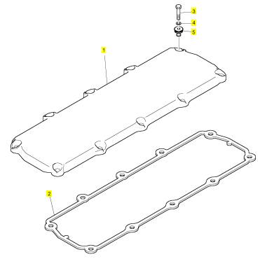
项目 零配件号码 新件号 描述
1 T401038 1 T401038 汽缸盖盖
2 CH12142 1 CH12142 密封垫
3 CH12143 10 CH12143 螺拴
4 CH11894 10 CH11894 垫圈
5 CH12140 10 CH12140 密封垫
项目 零配件号码 新件号 描述
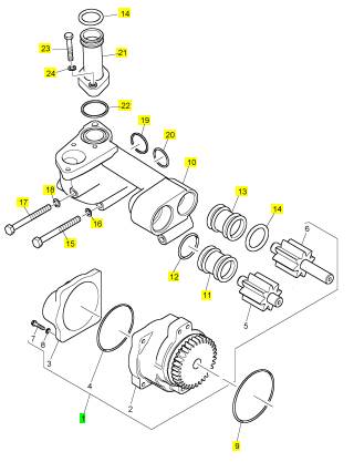
1 CH12314 1 CH12314 油泵
(1) CH12314 1 CH12314 油泵
9 CH10126 1 CH10126 密封O型圈
10 CH12316 1 CH12316 油肘管
11 CH10169 1 CH10169 联结器
12 CH11906 2 CH11906 密封O型圈
13 CH10170 2 CH10170 联结器
14 CH10135 2 CH10135 密封O型圈
15 CH12323 1 CH12323 螺拴
16 CH10277 1 CH10277 垫圈
17 CH10140 5 CH10140 螺拴
18 CH10277 5 CH10277 垫圈
19 CH12318 1 CH12318 密封O型圈
20 CH10228 1 CH10228 密封O型圈
21 T401160 1 T401160 油填隙料
22 T400368 1 T400368 密封O型圈
23 CH12447 2 CH12447 螺拴
24 CH10277 2 CH10277 垫圈
25 CH10135 1 CH10135 密封O型圈
项目 零配件号码 新件号 描述
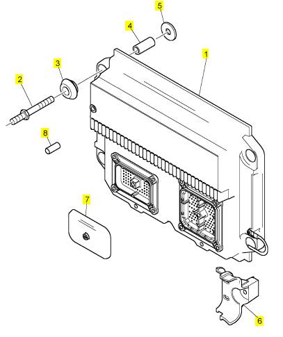
1 CH12895 1 CH12895 引擎控制组件ECM
2 CH10297 4 CH10297 图钉
3 CH10272 8 CH10272
4 CH10108 4 CH10108 间隔器
5 CH10279 8 CH10279 垫圈
6 CH11932 2 CH11932 托架
7 CH12655 1 CH12655 盖
8 CH12370 4 CH12370 帽
项目 零配件号码 新件号 描述
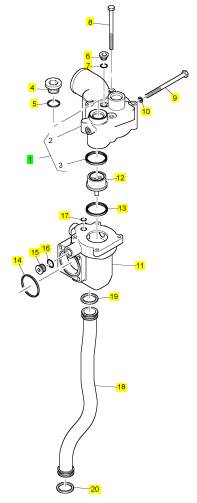
1 T401652 1 T401652 节温器壳
4 CH12474 2 CH12474 栓塞
5 CH11621 2 CH11621 密封O型圈
6 CH10285 1 CH10285 栓塞
7 CH10161 1 CH10161 密封O型圈
8 CH12171 4 CH12171 螺拴
9 CH12175 4 CH12175 螺拴
10 CH10277 4 CH10277 垫圈
11 CH12167 1 CH12167 调整器
12 CH11620 1 CH11620 节温器
13 CH12166 1 CH12166 密封垫 - 节温器壳
14 CH12165 1 CH12165 密封垫 - 节温器壳
15 CH10287 3 CH10287 栓塞
16 CH10146 3 CH10146 密封O型圈
17 CH12661 1 CH12661 密封O型圈
18 CH12168 1 CH12168 管
19 CH10201 1 CH10201 密封O型圈
20 CH10201 1 CH10201 密封O型圈
项目 零配件号码 新件号 描述
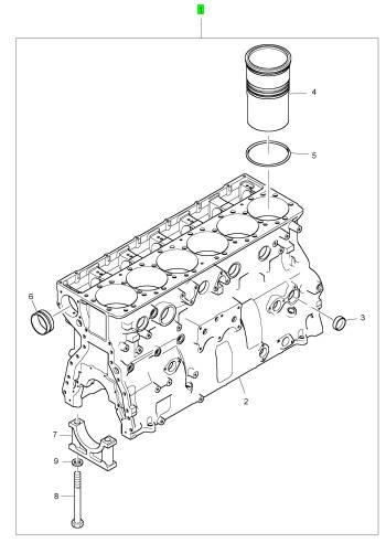
1 CH12684 1 CH12684 缸体组合
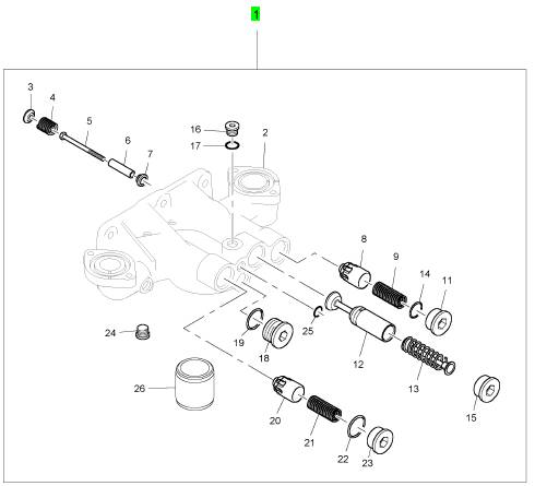
项目 零配件号码 新件号 描述
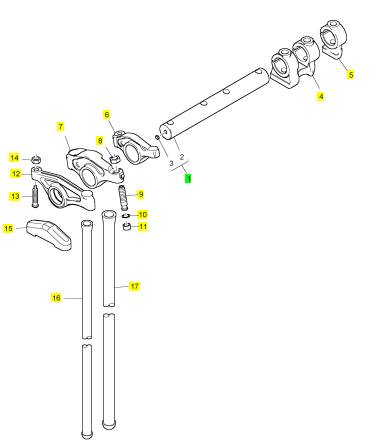
1 CH12481 1 CH12481 轴
4 CH12484 1 CH12484 摇臂座
5 CH12483 2 CH12483 轴环
6 T400226 1 T400226 摇臂
7 CH12511 1 CH12511 摇臂
8 CH12509 1 CH12509 螺帽
9 CH12512 1 CH12512 螺旋
10 CH10229 1 CH10229 密封O型圈
11 CH12702 1 CH12702 枢
12 CH12514 1 CH12514 摇臂
13 CH12513 2 CH12513 螺旋
14 CH11865 2 CH11865 螺帽
15 CH12278 12 CH12278 结轴块
16 CH12795 12 CH12795 PUSHROD
17 CH12808 6 CH12808 PUSHROD
项目 零配件号码 新件号 描述
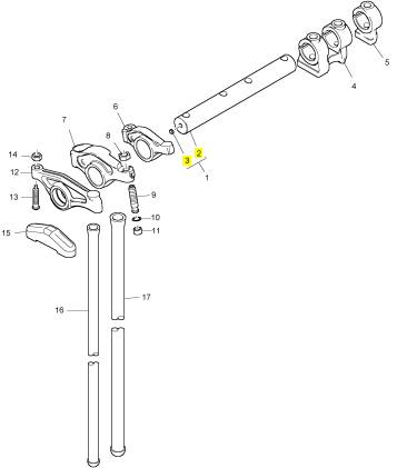
2 1 轴
3 CH12505 2 CH12505 栓塞
项目 零配件号码 新件号 描述
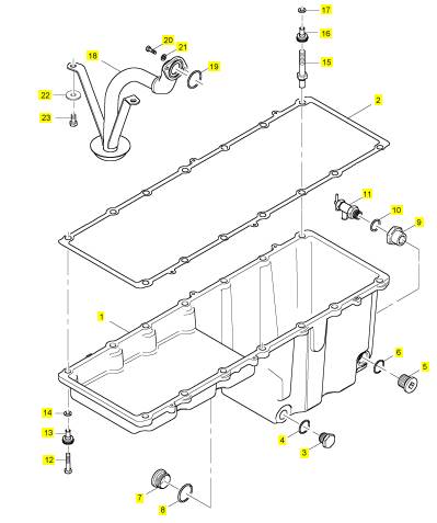
1 CH12117 1 CH12117 油底壳
2 CH12118 1 CH12118 密封垫 -油底壳
3 CH11571 1 CH11571 排泄栓塞
4 CH11573 1 CH11573 密封O型圈
5 T400251 1 T400251 栓塞
6 T400544 1 T400544 密封O型圈
7 T400251 1 T400251 栓塞
8 T400544 1 T400544 密封O型圈
9 T401275 1 T401275 承接器
10 T406205 1 T406205 密封O型圈
11 2461 A503 1 2461 A503 关闭阀
12 CH12124 13 CH12124 螺拴
13 CH12119 13 CH12119 密封垫
14 CH10113 13 CH10113 垫圈
15 CH12657 1 CH12657 图钉
16 CH12119 1 CH12119 密封垫
17 CH10113 1 CH10113 垫圈
18 T400250 1 T400250 管 - 油的吸入
19 CH10098 1 CH10098 密封O型圈
20 CH10041 2 CH10041 螺拴
21 T401636 2 T401636 垫圈
22 CH10099 2 CH10099 垫圈
23 CH12122 2 CH12122 螺拴
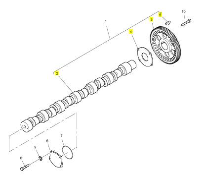
项目 零配件号码 新件号 描述
1 CH12436 1 CH12436 凸轮轴
6 CH12435 1 CH12435 盖
7 CH12437 1 CH12437 密封O型圈
8 CH11815 4 CH11815 螺拴
9 CH10277 4 CH10277 垫圈
10 CH12438 4 CH12438 螺拴
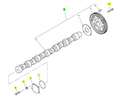
项目 零配件号码 新件号 描述
2 1 凸轮轴
3 CH12520 1 CH12520 凸轮轴传动机构
4 CH12519 1 CH12519 推力垫圈
5 CH10005 1 CH10005 半圆键
项目 零配件号码 新件号 描述
1 T401701 1 T401701 燃油滤清器
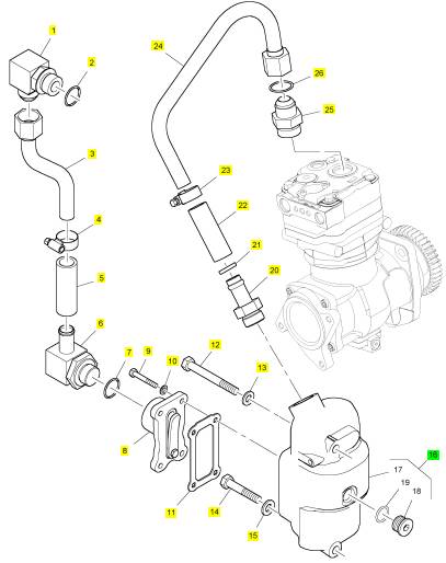
项目 零配件号码 新件号 描述
1 T401729 1 T401729 承接器
2 T400248 1 T400248 密封O型圈
3 T401731 1 T401731 管
4 T401735 2 T401735 摇臂座
5 T401734 1 T401734 水管
6 T401730 1 T401730 承接器
7 T400248 1 T400248 密封O型圈
8 T401725 1 T401725 阀
9 T401736 4 T401736 螺拴
10 CH10303 4 CH10303 垫圈
11 T401724 1 T401724 密封垫
12 T401732 1 T401732 螺拴
13 CH11819 1 CH11819 垫圈
14 T401737 1 T401737 螺拴
15 CH11819 1 CH11819 垫圈
16 T401723 1 T401723 管集箱箱
20 T401726 1 T401726 连接器
21 T400248 1 T400248 密封O型圈
22 T401733 1 T401733 水管
23 T401735 2 T401735 摇臂座
24 T401728 1 T401728 管
25 T401727 1 T401727 承接器
26 T401291 1 T401291 密封O型圈
项目 零配件号码 新件号 描述
1 T400172 1 T400172 机油冷却器
2 T400162 1 T400162 端帽
3 T400173 1 T400173 密封O型圈
4 CH10291 1 CH10291 栓塞
5 CH12240 1 CH12240 密封O型圈
6 CH12474 1 CH12474 栓塞
7 CH11621 1 CH11621 密封O型圈
8 CH10395 1 CH10395 联结器
9 CH12238 1 CH12238 密封O型圈
10 CH12238 1 CH12238 密封O型圈
11 CH11565 6 CH11565 螺拴
12 CH10277 6 CH10277 垫圈
13 T400175 1 T400175 端帽
14 T400173 1 T400173 密封O型圈
15 CH11375 1 CH11375 栓塞
16 CH10119 1 CH10119 密封O型圈
17 CH12447 4 CH12447 螺拴
18 CH10277 4 CH10277 垫圈
19 T400174 1 T400174 摇臂座
20 CH12662 1 CH12662 水管
21 T400174 1 T400174 摇臂座
22 CH12231 1 CH12231 密封O型圈
23 T401049 1 T401049 水肘管
24 CH10285 1 CH10285 栓塞
25 CH10161 1 CH10161 密封O型圈
26 CH10140 1 CH10140 螺拴
27 CH10277 1 CH10277 垫圈
28 CH12447 1 CH12447 螺拴
29 CH10277 1 CH10277 垫圈
d. Seat the sensor and tighten the bolt.
If the sensor will not seat, repair the sensor
or replace the sens or, as required.
Note: Do not remove the sensor from the bracket.
e. Ensure that the sensor is properly oriented
and that the harness is secured in the proper
location.
2. Verify that the repair eliminates the fault.
STOP.
Test Step 5. Install the Bypass Harness
for the Position Sensors
A. Turn the keyswitch to the OFF position.
B. Disconnect the J2/P2 ECM connector.
C. Use the following procedure for the crankshaft
position sensor:
a. Fabricate a harness from two wires. The wires
must reach between the crankshaft position
sensor and the P2 connector. Twisted pair
wiring is required. Ensure that the wires have
at least one twist per inch.
b. Connect one wire of the harness between
P2-35 and P401-2.
c. Connect the other wire between P2-25 and
P401-1.
D. Use the following procedure for the camshaft
position sensor:
a. Fabricate a harnes s from two wires. The wires
must reach between the camshaft position
sensor and the P2 connector. Twisted pair
wiring is required. Ensure that the wires have
at least one twist per inch.
b. Connect one wire of the harness between
P2-46 and P402-2.
c. Connect one wire of the harness between
P2-47 and P402-1.
E. Reconnect the P2 connector.
F. Attempt to start the engine. Verify that the original
fault is eliminated.
Expected Result:
The fault is eliminated with the installation of the
bypass harness.
Results:
• OK
Repair: Permanently install a new section of
harness.
STOP.
• Not OK
Repair: Verify that the correct terminals have been
installed in the correct location on the P2 ECM
connector. If the temporary harness was installed
correctly, remove the temporary harness. Connect
the original wiring.
Proceed to Test Step 6.
Test Step 6. Check the ECM
A. Turn the keyswitch to the OFF position.
B. Temporarily connect a test ECM.
C. Start the engine. Run the engine in order to repeat
the conditions when the fault occurs.
D. If the fault is eliminated with the test ECM,
reconnect the suspect ECM.
E. If the fault returns with the suspect ECM, replace
the ECM.
Verify that the repair eliminates the fault.
Expected Result:
The fault remains with the suspect ECM.
Results:
• OK
Repair: If the fault is eliminated with the test ECM
and the fault returns with the suspect ECM, replace
the ECM.
Verify that the repair eliminates the fault.
STOP.
• Not OK
Repair: Replace the sensor.
Verify that the repair eliminates the fault.
STOP.
This document has been printed from SPI². Not for Resale
![]() 110
110
Troubleshooting Section
KENR6224
Engine
Temperature
i02569910
Sensor
If the sensor is disconnected at the sensor connector,
the presenc e of pull-up voltage at the sensor
connector indicates that the wires from the sensor
connector to the ECM are not open or shorted to
Open or Short Circuit - Test
System Operation Description:
Use this procedure to troubleshoot any suspect faults
with the following sensors:
• Intake manifold air temperature sensor
• Coolant temperature sensor
• Fuel temperature sensor
This procedure covers the following diagnostic codes :
• 0110-03 Engine Coolant Temperature Sensor
voltage above normal
• 0110-04 Engine Coolant Temperature Sensor
voltage below normal
• 0172-03 Intake Manifold Air Temperatu, re Sensor
voltage above normal
• 0172-04 Intake Manifold Air Temperature Sensor
voltage below normal
• 0174-03 Fuel Temperature Sensor voltage above
normal
• 0174-04 Fuel Temperature Sensor voltage below
normal
The troubleshooting procedures for the diagnostic
codes of each temperature sensor are identical.
The temperature sensors are passiv e sensors that
have two terminals. The temperature sens ors do not
require supply voltage from the Electronic Control
Module (ECM).
Pull-up Voltage
The ECM continuously outputs a pull-up voltage
on the circuit for the sensor signal wire. The ECM
uses this pull-up voltage in order to detect an open
in the signal circuit. When the ECM detects the
presence of a voltage that is above a threshold on the
signal circuit, the ECM will generate an open circuit
diagnostic code (03) for the sens or.
ground. If the sensor is disconnected at the sensor
connector, the absence of pull-up voltage at the
sensor connec tor indicates an open in the signal wire
or a short to ground. If the sensor is disconnected at
the sensor connector and the voltage at the sensor
connector is different from pull-up voltage, the signal
wire is shorted to another wire in the harness.
This document has been printed from SPI². Not for Resale
![]()
![]()
![]() KENR6224
KENR6224
111
Troubleshooting Section
|
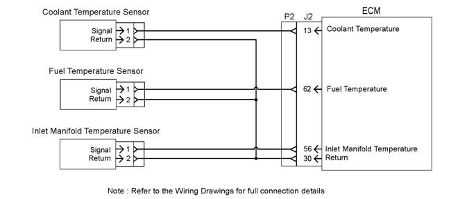
Schematic for the engine temperature sensors
Connectors and the Wiring
A. Turn the keyswitch to the OFF position.
g01287472
This document has been printed from SPI². Not for Resale
![]()
![]()
![]() 112
112
Troubleshooting Section
KENR6224
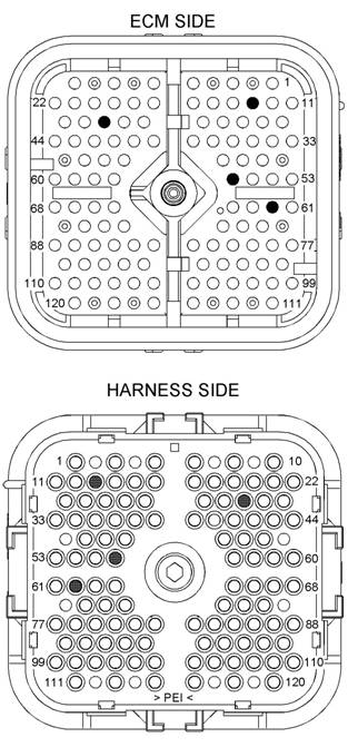
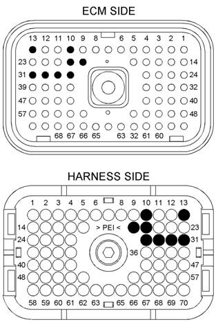
Illustration 44
P2 ECM connector
(P2-13) Engine coolant temperature
(P2-30) Return
(P2-56) Intake manifold air temperature
(P2-62) Fuel temperature
g01146245
|
wires that are associated with the temperature
sensors.
D. Check the allen head screw on each ECM
connector for the proper torque. Refer to the
Troubleshooting Guide, “Electrical Connectors -
Inspect” for the correct torque values.
E. Check the harness and wiring for abrasions and
for pinch points from each sensor to the ECM.
Expected Result:
All connectors, pins, and sockets are completely
coupled and/or inserted. The harness and wiring are
free of corrosion, of abrasion, and of pinc h points .
Results:
• OK – The connectors and wiring are OK. Proceed
to Test Step 2.
• Not OK – There is a fault in the connectors and/or
wiring.
Repair: Repair the connectors or wiring and/or
replace the connectors or wiring. Ensure that all of
the seals are properly in place and ensure that the
connectors are completely coupled.
Verify that the repair eliminates the fault.
STOP.
Codes
A. Connect the electronic service tool to the
diagnostic connector.
B. Turn the keyswitch to the ON position.
C. Monitor the active diagnostic code screen on the
electronic service tool. Check and record any
active diagnostic codes.
Note: Wait at least 15 seconds in order for the
diagnostic codes to bec ome ac tive.
D. Look for an 03 diagnostic code or an 04 diagnostic
code.
Expected Result:
B. Thoroughly inspect the ECM connectors and the
connectors for the suspect sensor. Refer to the
Troubleshooting Guide, “Electrical Connectors -
Inspect” for details.
|
Results:
•
This document has been printed from SPI². Not for Resale
![]() KENR6224
KENR6224
113
Troubleshooting Section
•
•
Repair: The fault may have been related to
a faulty connection in the harness. Carefully
reinspect the connectors and wiring. Refer to the
Troubleshooting Guide, “Electrical Connectors -
Inspect” for additional information.
STOP.
Not OK – An 03 diagnostic code is active at this
time. Proceed to Test Step 3.
Not OK – An 04 diagnostic code is active at this
time. Proceed to Test Step 6.
E. Turn the keyswitch to the OFF position.
F. Reconnect the P2 connector.
Expected Result:
Each check of the resistance is greater than 20,000
Ohms.
Results:
• OK – Each check of the resistance is greater than
20,000 Ohms. Proceed to Test Step 5.
|
A. Disconnect the suspect sensor at the sensor
connector.
B. Turn the keyswitch to the ON position.
C. Measure the voltage between terminal C (signal)
and terminal B (return) at the s ensor connector.
•
Not OK – At least one check of the resistanc e is
less than 20,000 Ohms.
Repair: The low resistance measurement indicates
a short circuit between two or more wires. Repair
the connectors or wiring and/or replace the
connectors or wiring.
STOP.
|
|
Expected Result:
The voltage is 5.5 ± 0.5 VDC.
Results:
pull-up voltage is present at the suspect sensor
connector.
Repair: The open circuit is in the sensor or the
wire between the sensor and the sensor connector.
Replace the sensor. Do not install the sensor in
the engine. Verify that no diagnostic codes are
active for the sus pect sensor before permanently
installing the sensor.
STOP.
Proceed to Test Step 4.
Test Step 4. Check the Signal Wire for a
Short Circuit
A. Turn the keyswitch to the OFF position.
B. Disconnect the P2 connector.
C. Measure the resistance between the terminal
for the sensor signal wire at the ECM and the
remaining terminals on the P2 connector.
D. Measure the resis tance between the terminal for
the sensor signal wire at the ECM and engine
ground.
|
A. Turn the keyswitch to the OFF position.
B. Install a jumper wire between terminal B and
terminal C on the connector for the suspect
sensor. Connect the jumper on the harness side
of the connector.
C. Turn the keyswitch to the ON position.
D. Wait at least 15 seconds for activation of the 04
diagnostic code.
Note: Monitor the “Active Diagnostic Codes” screen
on the electronic service tool before installing the
jumper wire and after installing the jumper wire.
E. Remove the jumper wire. Check for an 04
diagnostic code again.
F. Turn the keyswitch to the OFF position.
Expected Result:
An 04 diagnostic code is active when the jumper wire
is installed. An 03 diagnostic code is active when the
jumper wire is removed.
Results:
• OK – The engine harness and the ECM are okay.
This document has been printed from SPI². Not for Resale
![]() 114
114
Troubleshooting Section
KENR6224
•
Repair: Temporarily connect a new sensor to the
harness, but do not install the new sensor in the
engine. Verify that there are no active diagnostic
codes for the sensor. If there are no active
diagnostic codes for the sensor, permanently
install the new sensor. Clear any logged diagnostic
codes.
STOP.
Not OK – The 03 diagnostic code remains active
with the jumper in place. There is an open circuit
between the ECM and the sensor connector.
Proceed to Test Step 7.
|
A. Turn the keyswitch to the OFF position.
B. Check the operation of the ECM by creating an
open circuit at the ECM.
a. Remove the signal wire for the suspect s ensor
from the P2connector.
b. Remove the sensor return from terminal P2-30.
Note: Disconnecting the sensor return from the ECM
will generate an 03 diagnostic code for all sensors
|
|
A. Turn the keyswitch to the OFF position.
B. Disconnect the sus pect sensor from the harness
at the sensor connec tor.
C. Turn the keyswitch to the ON pos ition. Wait at
least 15 sec onds for activation of the diagnostic
codes.
D. Access the “Active Diagnostic Codes” screen on
the electronic service tool and check for an active
03 diagnostic code for the suspect sensor.
E. Turn the keyswitch to the OFF position.
Expected Result:
An 03 diagnostic code is now active for the suspect
sensor.
Results:
disconnecting the sensor. An 03 diagnostic code
bec ame active after the sensor was disconnected.
Repair: Temporarily connect a new sensor to the
harness, but do not install the new sensor in the
engine. Verify that there are no active diagnostic
codes for the sensor. If there are no active
diagnostic codes for the sensor, permanently
install the new sensor. Clear any logged diagnostic
codes.
Verify that the repair eliminates the fault.
STOP.
• Not OK – The 04 diagnostic code is still present.
Leave the sensor disconnected. Proceed to Test
Step 7.
|
the original diagnostic code. Delete the logged
diagnostic codes when you are finished.
c. Turn the keyswitch to the ON position. Monitor
the “Active Diagnostic Code” screen on the
electronic service tool. Wait at least 15 seconds
for activation of the code.
An 03 diagnostic code s hould be active for the
suspect sensor.
C. Check the operation of the ECM by creating a
short at the ECM.
a. Install a wire jumper between the terminals for
the sensor signal and the sensor return.
b. Monitor the “Active Diagnostic Code” screen
on the electronic service tool. Wait at least 15
seconds for activation of the code.
An 04 diagnostic code should be active when
the wire jumper is installed.
c. Remove the wire jumper and reconnect all
wires.
Expected Result:
An 03 diagnostic code is active when the sensor
signal wire is removed from the ECM connector. An
04 diagnos tic c ode is active when the signal wire is
connected to the sensor return.
Results:
in the wiring between the ECM and the sensor
connector.
Repair: If the code is active for more than one
sens or, the fault is most likely in the return wire for
the sensor. Repair the return wire for the sensor
or replace the harness.
This document has been printed from SPI². Not for Resale
![]() KENR6224
KENR6224
115
Troubleshooting Section
•
If the code is only active for one sensor, the fault is
most likely in the signal wire for the sensor. Repair
the signal wire for the sensor.
STOP.
Not OK – One of the following conditions exists:
The 03 diagnostic code is not active when the
sensor signal wire is disconnected. The 04
diagnostic code is not active when the wire jumper
is installed.
Repair: Replace the ECM. Refer to the
Troubleshooting Guide, “Replacing the ECM”.
Verify that the fault is eliminated.
STOP.
The “Oil Pressure” lamp indicates low engine oil
pressure. The severity of the fault is indicated by the
“Warning”, “Action Alert” or “Shutdown” lamps.
The “Action Alert” output indicates an engine fault
that is suffic iently severe so that the engine should be
shut down. The “Action Alert” output would normally
be used by the operator in order to open the circuit
breaker for the generator and the output would be
used to stop the engine.
Indicator Lamp
i02570763
Circuit - Test
System Operation Description:
The ECM has sev en available outputs that indicate
the operating status of the engine:
• Overspeed
• Coolant temperature
• Oil pressure
• Diagnostics
• Warning
• Action alert
• Shutdown
The outputs can be used to drive indicator lamps or
other controls. Each output provides a connection to
either the battery positive terminal or to the battery
negative terminal at a maximum current of 0.3 amp
when the output is ON. Each output gives an open
circuit when the output is OFF.
The “Diagnostics” output indicates that a fault exists
on the electronic system rather than with the engine.
The electronic s ervice tool should be used to
diagnose the fault.
The “Overspeed” output indicates that an overspeed
fault exists. The severity of the fault is indicated by
the “Warning”, “Action Alert” or “Shutdown” lamps.
The “Coolant Temperature” lamp indicates a high
coolant temperature fault. The severity of the fault
is indicated by the “Warning”, “Action Alert” or
“Shutdown” lamps.
This document has been printed from SPI². Not for Resale
![]()
![]()
![]() 116
116
Troubleshooting Section
KENR6224
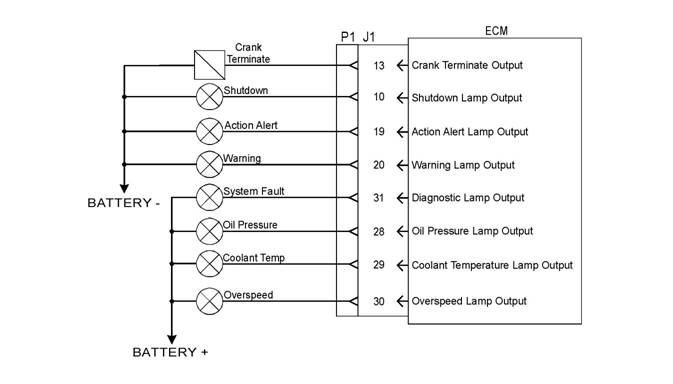
Illustration 45
Schematic diagram for the indicator outputs
Note: Outputs from the ECM can be used to operate
lamps or relays.
g01287870
This document has been printed from SPI². Not for Resale
![]()
![]()
![]()
![]() KENR6224
KENR6224
117
Troubleshooting Section
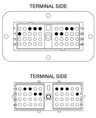
Illustration 46
Connections on the P1/J1 connector
(10) Shutdown lamp
(13) Engine running output
(19) Action alert lamp
g01287923
Illustration 47
Connections on the OEM connector
(3) Diagnostics lamp
(4) Warning lamp
(5) Action alert lamp
(8) Oil pressure lamp
(9) Overspeed lamp
(11) Engine running output
(16) Shutdown lamp
(17) Coolant temperature lamp
Test Step 1. Inspect the
Electrical
g01287960
(20) Warning lamp
(28) Oil pressure lamp
(29) Coolant temperature lamp
Connectors
and the Wiring
(30) Overspeed lamp
(31) Diagnostics lamp
A. Replace any indicator lamps that are blown.
B. Check the wiring in order to determine if status
indicators are present. Check that the status
indicators are controlled by the ECM. Refer to 45.
Some indicators may obtain engine status through
a data link.
Note: If status indicators are not directly controlled
by the ECM, stop this test.
C. Thoroughly inspect connector J1/P1, the wiring for
the indicator circuit and the connectors. Refer to
the Troubleshooting Guide, “Electrical Connectors
- Inspect”.
D. Perform a 45 N (10 lb) pull test on each wire that
is ass ociated with the status indicators.
E. Check that the Allen head screw that secures
the ECM connec tor is correctly tightened to a
maximum torque of 3 N·m (26.5 lb in).
This document has been printed from SPI². Not for Resale
![]() 118
118
Troubleshooting Section
KENR6224
F.
Check the harness and wiring from the status
indicators to the ECM for abrasion and pinch
points. All connectors, pins and sockets should be
completely mated or inserted. The harness and
the wiring should be free of corrosion, abras ion or
pinch points.
B. Turn the keyswitch to the OFF position.
C. Disconnect the ECM connector J1/P1.
D. Turn the keyswitch to the ON position.
E. Connect the jumper wire between the following
|
|
|
The lamps turn on and the lamps turn off per the
above description.
Results:
• OK – The connectors and wiring are OK. Proceed
to Test Step 2.
• Not OK – There is a fault in the connectors and/or
wiring.
Repair: Repair the connectors or wiring and/or
replace the connectors or wiring. Ensure that all of
the seals are properly in place and ensure that the
connectors are completely coupled.
Verify that the repair eliminates the fault.
STOP.
Short Circuit
A. Disconnect the control wire at the suspect
indicator lamp or the relay.
B. Attempt to start the engine and check the status
indicators .
Expected Result:
The short circuit has been eliminated.
Results:
• OK – - The short circuit is no longer present.
Repair: Repair the indicator or replace the
indicator.
STOP.
indicator. Proceed to Test Step 3.
with a Jumper Wire
A. Fabric ate a jumper wire that is 100 mm (4.0 inch)
in length with a Deutsch connector socket on both
ends.
|
lamp.
• Pin 10 and Battery +
• Pin 13 and Battery +
• Pin 19 and Battery +
• Pin 20 and Battery +
• Pin 28 and Battery -
• Pin 29 and Battery -
• Pin 30 and Battery -
• Pin 31 and Battery -
Expected Result:
Each lamp should illuminate only when the jumper is
inserted on the applicable pins in the ECM connector
P1.
Results:
• OK – The harness and indicators operate correctly.
Repair: Reconnect all connectors and recheck
the operation of the indicators. If the fault returns,
replace the ECM.
STOP.
• Not OK – There is a fault in the indic ator circuit.
Repair: Recheck electrical connections and the
wiring for damage, corrosion, or abrasion. Repair
the connectors and the wiring or replace the
connectors and the wiring.
Proceed to Test Step 4.
Circuit
A. Turn the keyswitch to the OFF position.
B. Remove the control wire for the suspect indicator
from the ECM connector P1. Refer to the
Troubleshooting Guide.
This document has been printed from SPI². Not for Resale
![]() KENR6224
KENR6224
119
Troubleshooting Section
C. Attempt to start the engine and chec k the status
indicators .
Expected Result:
All other indicator lamps operate c orrectly. The
suspect indicator lamp remains off.
Results:
• OK – The short is in the harness.
Repair: Repair the harness or replace the harness .
Verify that the fault is eliminated.
STOP.
• Not OK – The short circuit is present when the
circuit is disconnected from the ECM.
Repair: Dis connect the ECM connector J1/P1
and check for damage or corrosion. Refer to the
Troubleshooting Guide, “Electrical Connectors -
Inspect”.
If the fault is not eliminated, replace the ECM.
Refer to the Troubleshooting Guide, “Replacing
the ECM”.
STOP.
i02570748
Injector Solenoid Circuit - Test
System Operation Description:
Use this procedure to troubleshoot any suspect faults
with the injector solenoids.
Use this procedure for the following diagnostic codes:
• 0001-11 Cylinder #1 Injector other failure mode
• 0002-11 Cylinder #2 Injector other failure mode
• 0003-11 Cylinder #3 Injector other failure mode
• 0004-11 Cylinder #4 Injector other failure mode
• 0005-11 Cylinder #5 Injector other failure mode
• 0006-11 Cylinder #6 Injector other failure mode
• You have been directed to this procedure from the
Troubleshooting Guide, “Troubleshooting without a
Diagnostic Code”.
Perform this procedure under conditions that are
identical to the conditions that exist when the fault
occurs. Typically, faults with an injector solenoid
occur when the engine is warm and/or when the
engine is under vibration (heavy loads).
These engines have Electronic Unit Injectors (EUI)
that are mechanically actuated and electronically
controlled. The Engine Control Module (ECM) sends
a 105 volt pulse to each injector solenoid. The pulse
is sent at the proper time and for the correct duration
for a given engine load and speed. The solenoid
is mounted on top of the fuel injector body. The
105 volt pulse can be individually cut out to aid in
troubleshooting faults that involve misfires.
If an open circuit is detected in the solenoid circuit,
a diagnostic code is generated. The ECM continues
to try to fire the injector. If a short is detected, a
diagnostic code is generated. The ECM will disable
the s olenoid circ uit. The ECM will periodically try
to fire the injector. If the short circuit remains this
sequence of events will be repeated until the fault
is corrected.
An injector trim file must be programmed into the
ECM for each cylinder. Refer to the Troubleshooting
Guide, “Injector Trim File”.
Cylinder Cutout Test
The “Cylinder Cutout Test” is used in order to
determine the individual cylinder performance while
the engine is running. As one or more cylinders are
cut out during the test, the “Fuel Position” of each
injector is used in order to evaluate the performance
of the remaining cy linders that are firing. As the
different cylinders are cut out, a comparison of
the change in “Fuel Position” is used to identify
cylinders that are weak or misfiring. One reason for a
cylinder that is weak or misfiring is an injector that is
malfunctioning mechanically.
During the test, when a good injector is cut out, the
“Fuel Position” of the remaining injectors will increase.
This increase in the “Fuel Position” is caused by the
remaining injectors that are compensating for the cut
out injector. If a malfunctioning injector is cut out, the
“Fuel Position” for the remaining injectors will not
change. This is the result of the smaller quantity of
fuel that is needed to compensate for the power loss
from the malfunctioning injector. The “Cylinder Cutout
Test” is used to isolate a malfunctioning injector in
order to avoid replacement of injectors that are in
good repair.
Note: Prior to running the “Cylinder Cutout Test”, all
active diagnostic codes must be corrected.
Injector Solenoid Test
This document has been printed from SPI². Not for Resale