 English
 Espaol
 Franais
 阿拉伯
阿拉伯 中文
中文 Deutsch
 Italiano
 Português
 日本
日本 韩国
韩国 български
 hrvatski
 esky
esky Dansk
Dansk Nederlands
 suomi
suomi Ελληνικ
 印度
印度 norsk
norsk Polski
 Roman
Roman русский
 Svenska
Perkins1204柴油发动机控制器与传感器供应商,Perkins1204柴油发动机控制器与传感器技术价格规格咨询服务,Perkins1204柴油发动机控制器与传感器零配件供应,Perkins1204柴油发动机控制器与传感器售后服务中心,Perkins1204柴油发动机控制器与传感器,Perkins1204柴油发动机控制器与传感器详细的技术参数,

产品中心
Perkins1204柴油发动机控制器与传感器
详细描述
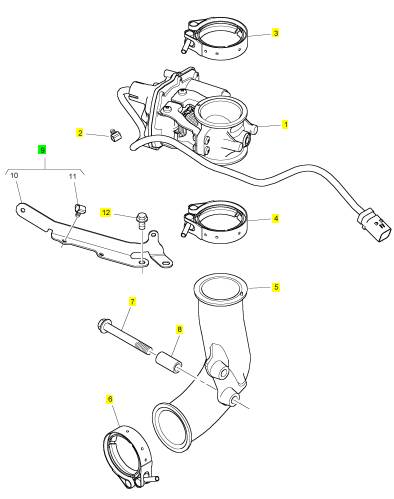
项目 零配件号码 新件号 描述
1 T408850 1 T408850 线束
项目 零配件号码 新件号 描述
2 1 线束
3 28170027 1 28170027 连接器
4 28170027 1 28170027 连接器
5 28170044 1 28170044 电力连接器
6 28170044 1 28170044 电力连接器
7 28170046 1 28170046 电力连接器
8 28170047 1 28170047 电力连接器
9 28170097 1 28170097 电力连接器
10 28170097 1 28170097 电力连接器
11 T406317 1 T406317 电力连接器
12 2817152 6 2817152 缆拉杆
13 T409319 1 T409319 电力连接器
14 T406207 1 T406207 电力连接器
15 T405558 1 T405558 电力连接器
16 T405558 1 T405558 电力连接器
17 T405558 1 T405558 电力连接器
18 T405558 1 T405558 电力连接器
19 T409393 30 T409393 缆拉杆
20 T400059 1 T400059 电力连接器
21 T407661 1 T407661 盖
22 28170049 1 28170049 电力连接器
23 1 电力连接器
24 1 电力连接器
25 1 电力连接器
项目 零配件号码 新件号 描述
1 T409623 2 T409623 线束
6 T409866 2 T409866 螺旋
7 T411276 1 T411276 托架
8 T408582 1 T408582 托架
9 2314 F003 2 2314 F003 螺旋
10 T408570 1 T408570 托架
11 2314 F003 2 2314 F003 螺旋
12 T408545 1 T408545 托架
13 2314 H033 1 2314 H033 螺旋
14 2817152 1 2817152 缆拉杆
15 T406842 1 T406842 托架
16 2314 H033 2 2314 H033 螺旋
17 T410485 1 T410485 托架
18 2314 F002 4 2314 F002 螺旋
19 2481 D501 1 2481 D501 夹
20 T405657 1 T405657 螺旋
21 T408589 1 T408589 托架
22 2314 F002 1 2314 F002 螺旋
23 2314 F002 1 2314 F002 螺旋
项目 零配件号码 新件号 描述
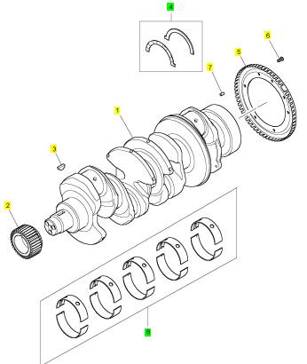
1 T411287 1 T420190 曲轴
1 T411287 1 T420190 曲轴
2 T406760 1 T406760 曲轴传动机构
3 0500012 1 0500012 半圆键
4 T409186 1 T409186 推力垫圈装备
(4) T418971 1 T418971 插入垫圈装备 -O/S
5 T411395 1 T411395 圆盘
6 2316 T244 3 2316 T244 螺旋
7 3313 A036 1 3313 A036 合钉
8 T410610 1 T410610 曲轴轴承装备
(8) T418684 1 T418684 曲轴轴承装备 -U/S
(8) T418689 1 T418689 曲轴轴承装备 -U/S
(8) T418691 1 T418691 曲轴轴承装备 -U/S
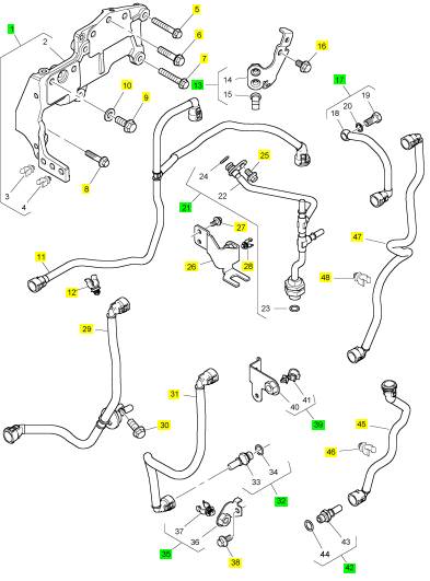
项目 零配件号码 新件号 描述
T409172 1 T409172 帽
1 T408626 1 T408626 托架
5 2314 H007 2 2314 H007 螺旋
6 2314 J003 3 2314 J003 螺旋
7 2314 H004 1 2314 H004 螺旋
8 2314 H006 3 2314 H006 螺拴
9 2314 J003 2 2314 J003 螺旋
10 2131 A010 2 2131 A010 垫圈
10 T407832 1 T407832 管夹
11 T408590 1 T408590 管 - 过滤器抽
12 T406604 1 T406604 管夹
13 T410796 1 T410796 托架
16 2314 H001 1 2314 H001 螺旋
17 T408588 1 T408588 管 - 漏走开
21 T410887 1 T410887 管 - 漏走开
25 2314 H002 1 2314 H002 螺旋
25 2314 H102 1 2314 H102 螺旋
26 T410797 1 T410797 托架
27 2314 F002 2 2314 F002 螺旋
28 T407832 1 T407832 管夹
29 T411490 1 T411490 管 - 过滤器抽
30 2314 F003 1 2314 F003 螺旋
31 T411476 1 T411476 以管输送 - ECM 加燃油过滤器
32 T407782 1 T407782 连接器
35 T408829 1 T408829 托架
38 2314 F002 1 2314 F002 螺旋
39 T418427 1 T418427 托架
39 T410088 1 T418427 托架
39 T413467 1 T413467 托架
42 T407782 1 T407782 连接器
45 T411478 1 T411478 管 - 低的压力燃油
46 T407832 1 T407832 管夹
47 T408641 1 T408641 管 - 低的压力燃油
48 T407832 1 T407832 管夹
项目 零配件号码 新件号 描述
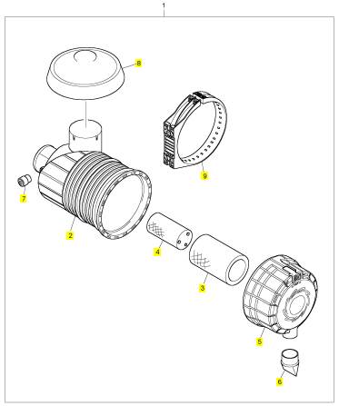
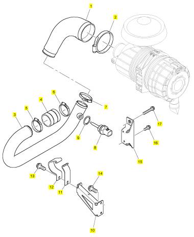
1 2652 C841 1 2652 C841 空气过滤器组合
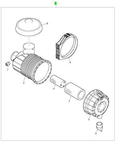
项目 零配件号码 新件号 描述
2 1 空气过滤器体
3 2652 C845 1 2652 C845 主空气过滤器
4 2652 C847 1 2652 C847 安全空气过滤器
5 26510412 1 26510412 盖
6 26510350 1 26510350 阀
7 2652 C806 1 2652 C806 指压计
8 2652 C810 1 2652 C810 帽
9 2652 C839 1 2652 C839 托架
项目 零配件号码 新件号 描述
1 T410854 1 T410854 水管 -空气
2 2481 D078 1 2481 D078 水管夹
3 T410878 1 T410878 水管 -空气
4 T408986 1 T408986 水管 -空气
5 2481 D075 1 2481 D075 水管夹
6 2481 D075 1 2481 D075 水管夹
7 2481 D075 1 2481 D075 水管夹
8 T407354 1 T407354 温度感应传感器
9 2415 H015 1 2415 H015 密封O型圈
10 T410803 1 T410803 托架
11 T408224 1 T408224 砂箱夹
12 T408225 1 T408225 砂箱夹
13 2314 J003 1 2314 J003 螺旋
14 2314 J003 2 2314 J003 螺旋
15 T409887 1 T409887 托架
16 2314 H003 2 2314 H003 螺旋
17 2314 H004 2 2314 H004 螺旋
项目 零配件号码 新件号 描述
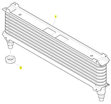
1 T408634 1 T408634 冷却器
2 T409185 2 T409185 螺帽
项目 零配件号码 新件号 描述
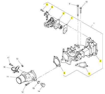
1 T412508 1 T412508 汽缸盖组合

项目 零配件号码 新件号 描述
2313 H244 1 2313 H244 图钉
2314 H013 2 2314 H013 螺旋
2318 A603 1 2318 A603 螺帽
T407823 1 T407823 间隔器
1 T414724 1 T414724 组件
9 2314 H019 3 2314 H019 螺旋
10 2314 H007 2 2314 H007 螺旋
11 T419339 1 T419339 管 -空气
11 T406921 1 检查历史 管 -空气
12 2314 H005 3 2314 H005 螺旋
13 0650594 1 0650594 栓塞
14 3278 A006 1 3278 A006 栓塞
15 2415 H003 1 2415 H003 密封O型圈
16 T409511 1 T409511 电磁线圈
17 2314 F006 1 2314 F006 螺旋
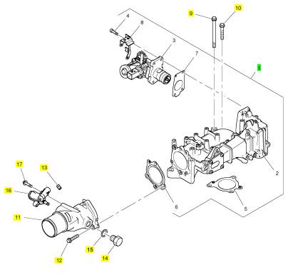
项目 零配件号码 新件号 描述
2 1 组件
3 T410643 1 T410643 阀
4 2311 D040 4 2311 D040 螺旋
5 T405093 1 T405093 密封垫片
6 T405854 1 T405854 密封垫片
7 T407955 1 T407955 密封垫片
8 T410435 1 T410435 托架
项目 零配件号码 新件号 描述
1 T410326 1 T410326 停机电磁阀
2 T407702 1 T407702 管夹
3 T406192 1 T406192 砂箱夹
4 T406192 1 T406192 砂箱夹
5 T408603 1 T408603 排气肘管
6 T406192 1 T406192 砂箱夹
7 3218 J025 2 3218 J025 螺旋
8 3313 A029 2 3313 A029 间隔器
9 T409419 1 T409419 托架
12 2314 H002 2 2314 H002 螺旋
|
Troubleshooting |
|
1204E-E44TA, 1204E-E44TTA and 1206E-E66TA Industrial Engines |
|
BK1 (Engine) MK1 (Engine) ML1 (Engine) |
|
This document is printed from SPI². Not for RESALE |
![]()
![]()
![]()
![]()
|
Important Safety Information |
|
Most accidents tha t involve produc t op eration, ma intena nc e and repair are caus ed by failure to ob serve basic safety rules or precautions . An accident can often be avoided by recog nizing pote ntially ha za rdous situations before an accident oc curs . A person mus t be alert to pote ntial ha za rds. This person should also ha ve the ne cessary training, skills and tools to perform the se func tions properly. |
|
Improper operation, lubrication, maintenance or repair of this product can be dangerous and could result in injury or death. |
|
Do not operate or perform any lubrication, maintenance or repair on this product, until you have read and understood the operation, lubrication, maintenance and repair information. |
|
Sa fety precautions and warning s are provided in this ma nua l and on the produc t. If the se ha za rd warning s are not he eded, bod ily injury or death could oc cur to you or to othe r persons . |
|
The ha za rds are identified by the “Safety Alert Symb ol” and followed by a “Signa l Word” suc h as “DANGER”, “WARNING” or “CAUTION”. The Sa fety Alert “WARNING” label is shown below. |
|
The me aning of this safety alert symb ol is as follows: |
|
Attention! Become Alert! Your Safety is Involved. |
|
The me ssage tha t appears und er the warning explains the ha za rd and can be either written or pictorially presente d. |
|
Op erations tha t ma y caus e produc t dama ge are identified by “NOTICE” labels on the produc t and in this pub lication. |
|
Perkins cannot anticipate every possible circumstance that might involve a potential hazard. The warnings in this publication and on the product are, therefore, not all inclusive. If a tool, procedure, work method or operating technique that is not specifically recommended by Perkins is used, you must satisfy yourself that it is safe for you and for others. You should also ensure that the product will not be damaged or be made unsafe by the operation, lubrication, maintenance or repair procedures that you choose. |
|
The informa tion, specifications , and illustrations in this pub lication are on the basis of informa tion tha t was available at the time tha t the pub lication was written. The specifications , torque s, pressure s, me asure me nts , adjustme nts , illustrations , and othe r items can cha ng e at any time. These cha ng es can affect the service tha t is given to the produc t. Ob tain the comp lete and mos t current informa tion before you start any job. Pe rkins dealers or Pe rkins distributors ha ve the mos t current informa tion available. |
|
When replacement parts are required for this product Perkins recommends using Perkins replacement parts. Failure to heed this warning can lead to prema- ture failures, product damage, personal injury or death. |
|
This document is printed from SPI². Not for RESALE |
![]()
![]()
|
KENR9116-01 |
|
3 Table of Contents |
|
Table of Contents |
|
Engine Stalls at Low RPM .................................... 94 Engine Top Speed Is Not Obtained ...................... 96 Engine Vibration Is Excessive ............................ 101 Exhaust Has Excessive Black Smoke ................ 102 Exhaust Has Excessive White Smoke ................ 104 Fuel Consumption Is Excessive .......................... 106 Fuel Contains Water ........................................... 108 Fuel Rail Pressure Problem ................................ 109 Fuel Temperature Is High .................................... 117 Inlet Air Is Restricted ............................................ 119 Inlet Air Temperature Is High .............................. 120 Intake Manifold Air Pressure Is High .................. 121 Intake Manifold Air Pressure Is Low ................... 122 Intake Manifold Air Temperature Is High ............. 123 NRS Exhaust Gas Temperature Is High ............ 124 NRS Mass Flow Rate Problem ........................... 127 Oil Consumption Is Excessive ............................ 130 Oil Contains Coolant ........................................... 132 Oil Contains Fuel ................................................ 133 Oil Pressure Is Low ............................................. 134 Power Is Intermittently Low or Power Cutout Is |
|
Troubleshooting Section |
|
Electronic Troubleshooting |
|
Welding Precaution ................................................. 5 System Overview .................................................... 5 Glossary ................................................................ 12 Electronic Service Tools ........................................ 16 Indicator Lamps .................................................... 18 Replacing the ECM ............................................... 21 Self-Diagnostics .................................................... 22 Sensors and Electrical Connectors ....................... 22 Engine Wiring Information .................................... 31 ECM Harness Connector Terminals ..................... 36 |
|
Programming Parameters |
|
Programming Parameters ..................................... 37 Test ECM Mode .................................................... 37 Factory Passwords ............................................... 37 Flash Programming .............................................. 38 Injector Code - Calibrate ....................................... 39 Mode Switch Setup ............................................... 40 Throttle Setup ....................................................... 41 Multiposition Switch Setup .................................... 44 |
|
Intermittent ........................................................ 136 Valve Lash Is Excessive ..................................... 141 |
|
Troubleshooting with a Diagnostic Code |
|
Diagnostic Trouble Codes ................................... 142 Diagnostic Code Cross Reference ..................... 147 No Diagnostic Codes Detected ........................... 151 |
|
Customer Specified Parameters |
|
Customer Specified Parameters ........................... 45 Customer Specified Parameters Table ................. 51 Customer Specified Parameters Worksheet ......... 54 |
|
Troubleshooting with an Event Code Event Codes ...................................................... 152 |
|
Diagnostic Functional Tests |
|
System Configuration Parameters System Configuration Parameters ........................ 58 |
|
5 Volt Sensor Supply Circuit - Test ..................... 154 Analog Throttle Position Sensor Circuit - Test .... 163 CAN Data Link Circuit - Test ............................... 168 Data Link Circuit - Test ........................................ 172 Diesel Particulate Filter Identification Signal - |
|
Symptom Troubleshooting Acceleration Is Poor or Throttle Response Is |
|
Poor .................................................................... 60 Alternator Is Noisy ................................................ 66 Alternator Problem ................................................ 66 Battery Problem .................................................... 66 Coolant Contains Oil ............................................. 67 Coolant Level Is Low ............................................ 67 Coolant Temperature Is High ................................ 68 Crankcase Breather Ejects Oil .............................. 71 Crankcase Fumes Disposal Tube Has Oil Draining ............................................................... 72 Cylinder Is Noisy ................................................... 73 Diesel Particulate Filter Collects Excessive Soot .. 74 Diesel Particulate Filter Temperature Is Low ........ 75 ECM Does Not Communicate with Other Modules .............................................................. 76 ECM Will Not Accept Factory Passwords ............. 76 Electronic Service Tool Does Not Communicate .. 77 Engine Cranks but Does Not Start ........................ 78 Engine Does Not Crank ........................................ 84 Engine Has Early Wear ........................................ 85 Engine Has Mechanical Noise (Knock) ................ 85 Engine Misfires, Runs Rough or Is Unstable ........ 86 Engine Overspeeds .............................................. 91 Engine Shutdown Occurs Intermittently ............... 92 Engine Speed Does Not Change .......................... 93 |
|
Test ................................................................... 179 Digital Throttle Position Sensor Circuit - Test ..... 183 ECM Memory - Test ............................................ 192 Electrical Connectors - Inspect ........................... 193 Engine Pressure Sensor Open or Short Circuit - Test ................................................................... 197 Engine Speed/Timing Sensor Circuit - Test ........ 204 Engine Temperature Sensor Open or Short Circuit - Test ................................................................... 212 Engine Temperature Sensor Open or Short Circuit - Test ................................................................... 217 Ether Starting Aid - Test ...................................... 224 Fuel Pump Relay Circuit - Test ........................... 228 Glow Plug Starting Aid - Test .............................. 236 Idle Validation Switch Circuit - Test ..................... 242 Ignition Keyswitch Circuit and Battery Supply Circuit - Test ................................................................... 248 Indicator Lamp Circuit - Test ............................... 255 Injector Data Incorrect - Test ............................... 258 Injector Solenoid Circuit - Test ............................ 260 Mode Selection Cir, cuit - Test .............................. 267 Motorized Valve - Test ........................................ 271 PTO Switch Circuit - Test .................................... 276 Sensor Calibration Required - Test ..................... 279 Solenoid Valve - Test .......................................... 282 |
|
This document is printed from SPI². Not for RESALE |
![]()
|
4 |
|
KENR9116-01 |
|
Table of Contents |
|
Soot Sensor - Test .............................................. 288 Throttle Switch Circuit - Test ............................... 291 Valve Position Sensor - Test ............................... 295 Water In Fuel Sensor - Test ................................ 301 |
|
Index Section |
|
Index ................................................................... 306 |
|
This document is printed from SPI². Not for RESALE |
![]()
|
KENR9116-01 |
|
5 Troubleshooting Section |
|
Troubleshooting Section |
|
Electronic Troubleshooting |
|
i04029202 |
|
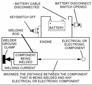
Welding Precaution |
|
Correct welding procedures are necessary in order to avoid damage to the following components: |
|
• Electronic Control Module (ECM) on the engine • Clean Emissions Module (CEM) • Sensors |
|
g01143634 |
|
Illustration 1 |
|
• Associated components |
|
Service welding guide (typical diagram) |
|
Components for the driven equipment should also be considered. When possible, remove the component that requires welding. When welding on an engine that is equipped with an ECM and removal of the component is not possible, the following procedure must be followed. This procedure minimizes the risk to the electronic components. |
|
5. When possible, connect the ground clamp for the welding equipment directly to the engine component that will be welded. Place the clamp as close as possible to the weld. Close positioning reduces the risk of welding current damage to the engine bearings, to the electrical components, and to other components. |
|
1. Stop the engine. Remove the electrical power from the ECM. |
|
6. Protect the wiring harnesses from welding debris and/or from welding spatter. |
|
2. Ensure that the fuel supply to the engine is turned off. |
|
7. Use standard welding procedures to weld the materials together. |
|
3. Disconnect the negative battery cable from the battery. If a battery disconnect switch is installed, open the switch. |
|
i04155807 |
|
System Overview |
|
4. Disconnect all electronic components from the wiring harnesses. Include the following components: |
|
The engine has an electronic control system. The system also monitors the Diesel Particulate Filter (DPF) and the NOx Reduction System (NRS). |
|
• Electronic components for the driven equipment |
|
• ECM |
|
The control system consists of the following components: |
|
• Sensors |
|
• Electronically controlled valves • Relays |
|
• Electronic Control Module (ECM) • Software (flash file) • Wiring |
|
• Aftertreatment ID module |
|
NOTICE |
|
• Sensors |
|
Do not use electrical components (ECM or ECM sen- sors) or electronic component grounding points for grounding the welder. |
|
• Actuators |
|
This document is printed from SPI². Not for RESALE |
![]()
![]()
![]()
![]()
|
6 |
|
KENR9116-01 |
|
Troubleshooting Section |
|
The following information provides a general description of the control system. Refer to Systems Operation, Testing, and Adjusting for detailed information about the control system. |
|
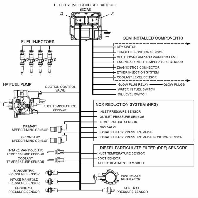
Electronic Control Circuit Diagram |
|
g02476570 |
|
Illustration 2 |
|
Electronic control circuit diagram for the 1204E-E44 engine |
|
This document is printed from SPI². Not for RESALE |
![]()
![]()
|
KENR9116-01 |
|
7 Troubleshooting Section |
|
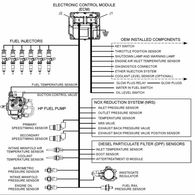
g02476572 |
|
Illustration 3 |
|
Electronic control circuit diagram for the 1206E-E66 engine |
|
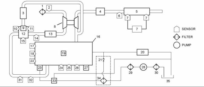
Block Diagram |
|
Refer to Illustration 4 and Illustration 5 for block diagrams of the control system. |
|
This document is printed from SPI². Not for RESALE |
![]()
![]()
|
8 |
|
KENR9116-01 |
|
Troubleshooting Section |
|
g02477761 |
|
Illustration 4 |
|
Block diagram for the 1204E and 1206E engines with a single turbocharger |
|
(1) Air cleaner |
|
(13) Air-to-air aftercooler |
|
(25) Oil pressure sensor |
|
(2) Air inlet temperature sensor (3) NRS cooler |
|
(14) Wastegate regulator (15) NRS outlet pressure sensor (16) Engine (17) Coolant temperature sensor (18) Primary speed/timing sensor (19) Fuel injectors |
|
(26) Barometric pressure sensor (27) ECM (28) Electric fuel lift pump (29) Primary fuel filter |
|
(4) Exhaust back pressure valve (5) Diesel Oxidation Catalyst (DOC) and Diesel Particulate Filter (DPF) (6) DPF inlet temperature sensor (7) Soot sensor (8) Turbocharger (9) NRS valve (10) NRS temperature sensor (11) NRS inlet pressure sensor (12) NRS mixer |
|
(30) In-line fuel strainer |
|
(31) Intake manifold pressure sensor (32) Intake manifold air temperature sensor (33) Transfer pump inlet regulator (34) Secondary fuel filter (35) Fuel tank |
|
(20) Return fuel cooler |
|
(21) Return fuel pressure relief valve (22) Secondary speed/timing sensor (23) High-pressure fuel pump/transfer pump/fuel temperature sensor (24) Fuel rail pressure sensor |
|
This document is printed from SPI². Not for RESALE |
![]()
![]()
|
KENR9116-01 |
|
9 Troubleshooting Section |
|
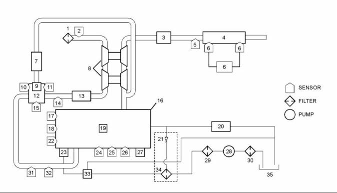
g02477778 |
|
Illustration 5 |
|
Block diagram for the 1204E-E44TTA engine with twin turbochargers |
|
(1) Air cleaner |
|
(13) Air-to-air aftercooler |
|
(25) Oil pressure sensor |
|
(2) Air inlet temperature sensor (3) Exhaust back pressure valve (4) Diesel Oxidation Catalyst (DOC) and Diesel Particulate Filter (DPF) (5) DPF inlet temperature sensor (6) Soot sensor (7) NRS cooler (8) Turbochargers (9) NRS valve |
|
(14) Wastegate regulator (15) NRS outlet pressure sensor (16) Engine (17) Coolant temperature sensor (18) Primary speed/timing sensor (19) Fuel injectors |
|
(26) Barometric pressure sensor (27) ECM (28) Electric fuel lift pump (29) Primary fuel filter |
|
(30) In-line fuel strainer |
|
(31) Intake manifold pressure sensor (32) Intake manifold air temperature sensor (33) Transfer pump inlet regulator (34) Secondary fuel filter (35) Fuel tank |
|
(20) Return fuel cooler |
|
(21) Return fuel pressure relief valve (22) Secondary speed/timing sensor (23) High-pressure fuel pump/transfer pump/fuel temperature sensor (24) Fuel rail pressure sensor |
|
(10) NRS temperature sensor (11) NRS inlet pressure sensor (12) NRS mixer |
|
System Operation |
|
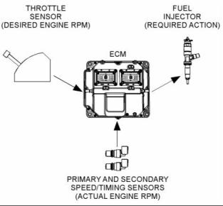
Engine Governor |
|
The ECM governs the engine. The ECM determines the timing, the injection pressure, and the amount of fuel that is delivered to each cylinder. These factors are based on the actual conditions and on the desired conditions at any given time during starting and operation. |
|
The governor uses the throttle position sensor to determine the desired engine speed. The governor compares the desired engine speed to the actual engine speed. The actual engine speed is determined through interpretation of the signals that are received by the ECM from the engine speed/timing sensors. If the desired engine speed is greater than the actual engine speed, the governor injects more fuel in order to increase engine speed. |
|
This document is printed from SPI². Not for RESALE |
![]()
![]()
|
10 |
|
KENR9116-01 |
|
Troubleshooting Section |
|
Fuel Injection |
|
The ECM sends a high voltage signal to the injector solenoids in order to energize the solenoids. By controlling the timing and the duration of the high voltage signal, the ECM can control the following aspects of injection: |
|
• Injection timing • Fuel delivery |
|
The flash file inside the ECM establishes certain limits on the amount of fuel that can be injected. The FRC Fuel Limit is a limit that is based on the intake manifold pressure. The FRC Fuel Limit is used to control the air/fuel ratio for control of emissions. When the ECM senses a higher intake manifold pressure, the ECM increases the FRC Fuel Limit. A higher intake manifold pressure indicates that there is more air in the cylinder. When the ECM increases the FRC Fuel Limit, the ECM allows more fuel into the cylinder. |
|
g01860934 |
|
Illustration 6 |
|
Typical example |
|
The Rated Fuel Limit is a limit that is based on the power rating of the engine and on the engine rpm. The Rated Fuel Limit is like the rack stops and the torque spring on a mechanically governed engine. The Rated Fuel Limit provides the power curves and the torque curves for a specific engine family and a specific engine rating. All of these limits are determined at the factory. These limits cannot be changed. |
|
The desired engine speed is typically determined by one of the following conditions: |
|
• The position of the throttle |
|
• The desired engine speed in Power Take-Off (PTO) |
|
Timing Considerations |
|
Once the governor has determined the amount of fuel that is required, the governor must determine the timing of the fuel injection. Fuel injection timing is determined by the ECM after considering input from the following components: |
|
Customer Parameters and Engine Speed Governing |
|
A unique feature with electronic engines is customer specified parameters. These parameters allow the owner of the machine to fine-tune the ECM for engine operation. Fine-tuning the ECM allows the machine owner to accommodate the typical usage of the machine and the power train of the machine. |
|
• Coolant temperature sensor |
|
• Intake manifold air temperature sensor • Intake manifold pressure sensor • Barometric pressure sensor |
|
Many of the customer parameters provide additional restrictions on the actions that will be performed by the ECM in response to input from the operator. The PTO Top Engine Limit is an engine rpm limit that is used by the ECM to limit the fuel during operation of the PTO. The ECM will not fuel the injectors above this rpm. |
|
The ECM adjusts timing for optimum engine |
|
performance and fuel economy. Actual timing and desired timing cannot be viewed with the electronic service tool. The ECM determines the location of top center of the number one cylinder from the signals that are provided by the engine speed/timing sensors. The ECM determines when injection should occur relative to top center position. The ECM then provides the signal to the injector at the desired time. |
|
Some parameters are intended to notify the operator of potential engine damage (engine monitoring parameters). Some parameters enhance fuel economy (machine speed, engine speed limit, and idle shutdown). Other parameters are used to enhance the engine installation into the machine. Other parameters are used to provide operating information to the owner of the machine. |
|
This document is printed from SPI². Not for RESALE |
![]()
![]()
|
KENR9116-01 |
|
11 Troubleshooting Section |
|
Other ECM Functions for Performance |
|
“Lifetime Total Engine Revolutions” is the total number of revolutions that have been completed by the engine crankshaft. |
|
The ECM can also provide enhanced control of the engine for machine functions such as controlling the cooling fan. Refer to Troubleshooting, “Configuration Parameters” for supplemental information about the systems that can be monitored by the ECM in order to provide enhanced machine performance, fuel economy, and convenience for the operator. |
|
“Average Load Factor” provides relative engine operating information. “Average Load Factor” compares actual operating information of the engine to the maximum engine operation that is available. “Average Load Factor” is determined by using “Total Max Fuel”, “Total Idle Fuel”, and “Total Fuel”. All of these parameters are available with the electronic service tool. These parameters are available within the menu for “Current Totals”. |
|
ECM Lifetime Totals |
|
The ECM maintains total data of the engine for the following parameters: |
|
Programmable Parameters |
|
Certain parameters that affect engine operation may be changed with the electronic service tool. The parameters are stored in the ECM, and the parameters are protected from unauthorized changes by passwords. These parameters are either system configuration parameters or customer parameters. |
|
• “Total Operating Hours” • “Engine Lifetime Hours” • “Total Idle Time” |
|
• “Total Idle Fuel” |
|
System configuration parameters are set at the factory. System configuration parameters affect emissions or power ratings within an engine family. Factory passwords must be obtained and factory passwords must be used to change the system configuration parameters. |
|
• “Total Fuel” |
|
• “Total Max Fuel” |
|
• “Engine Starts” |
|
Customer parameters are variable. Customer parameters affect the following characteristics within the limits that are set by the factory, by the monitoring system, and by PTO operation: |
|
• “Lifetime Total Engine Revolutions” • “Average Load Factor” |
|
The “Total Operating Hours” is the operating hours of the engine. The operating hours do not include the time when the ECM is powered but the engine is not running. |
|
• Rpm ratings |
|
• Power ratings |
|
Customer passwords may be required to change customer specified parameters. |
|
The “Engine Lifetime Hours” is the number of hours when electrical power has been applied to the engine. These hours will include the time when the ECM is powered but the engine is not running. |
|
Some of the parameters may affect engine operation in an unusual way. An operator might not expect this type of effect. Without adequate training, these parameters may lead to power complaints or performance complaints even though the performance of the engine is to the specification. |
|
“Total Idle Time” and “Total Idle Fuel” can include operating time when the engine is not operating under a load. |
|
Fuel Information can be displayed in US gallons or in liters. |
|
Refer to Troubleshooting, “Configuration Parameters” for additional information on this subject. |
|
“Total Fuel” is the total amount of fuel that is consumed by the engine during operation. |
|
Passwords |
|
“Total Max Fuel” is the maximum amount of fuel that could have been consumed by the engine during operation. |
|
System configuration parameters are protected by factory passwords. Factory passwords are calculated on a computer system that is available only to Perkins Distributors. Since factory passwords contain alphabetic characters, only the electronic service tool may change system configuration parameters. System configuration parameters affect the power rating family or emissions. |
|
“Engine Starts” is the total number of times when the engine has been started. |
|
This document is printed from SPI². Not for RESALE |
![]()
|
12 |
|
KENR9116-01 |
|
Troubleshooting Section |
|
Customer parameters can be protected by customer passwords. The customer passwords are programmed by the customer. Factory passwords can be used to change customer passwords if customer passwords are lost. |
|
Communication Adapter Tool – The communication adapter provides a communication link between the ECM and the electronic service tool. |
|
Coolant Temperature Sensor – The coolant temperature sensor detects the engine coolant temperature for all normal operating conditions and for engine monitoring. |
|
Refer to Troubleshooting, “Factory Passwords” for additional information on this subject. |
|
Data Link – The data link is a serial communication port that is used for communication with other devices such as the electronic service tool. |
|
i04156374 |
|
Glossary |
|
Derate – Certain engine conditions will generate event codes. Also, engine may be derated. The map for the engine derate is programmed into the ECM software. The type of derate can be one or more of three types: reduction of rated power, reduction of rated engine speed, and reduction of rated machine speed for OEM products. |
|
Active Diagnostic Code – An active diagnostic code alerts the operator or the service technician that an electronic system malfunction is currently present. Refer to the term “Diagnostic Code” in this glossary. |
|
Aftertreatment – Aftertreatment is a system that is used to remove pollutants from exhaust gases. The system consists of a Diesel Oxidation Catalyst (DOC) and a Catalyzed Diesel Particulate Filter (CDPF). |
|
Desired Engine Speed – The desired engine speed is input to the electronic governor within the ECM. The electronic governor uses the signal from the throttle position sensor, the engine speed/timing sensor, and other sensors in order to determine the desired engine speed. |
|
Alternating Current (AC) – Alternating current is an electric current that reverses direction at a regular interval that is reoccurring. |
|
Diagnostic Trouble Code – A diagnostic trouble code is sometimes referred to as a fault code. These codes indicate an electronic system malfunction. |
|
Before Top Center (BTC) – BTC is the 180 degrees of crankshaft rotation before the piston reaches the top center position in the normal direction of rotation. |
|
Diagnostic Lamp – The diagnostic lamp is also called the warning lamp. The diagnostic lamp is used to warn the operator of the presence of an active diagnostic code. The lamp may not be included in all applications. |
|
Breakout Harness – A breakout harness is a test harness that is designed to connect into the engine harness. This connection allows a normal circuit operation and the connection simultaneously provides a Breakout T in order to measure the signals. |
|
Diesel Oxidation Catalyst – The Diesel Oxidation Catalyst is also known as the (DOC). The DOC is a device in the exhaust system that oxidizes certain elements in the exhaust gases. These elements can include carbon monoxide (CO), hydrocarbons and the soluble organic fractions (SOF) of particulate matter. |
|
Bypass Circuit – A bypass circuit is a circuit that is used as a substitute circuit for an existing circuit. A bypass circuit is typically used as a test circuit. |
|
CAN Data Link (see also J1939 CAN Data Link) – The CAN Data Link is a serial communications port that is used for communication with other microprocessor-based devices. |
|
Digital Sensor Return – The common line (ground) from the ECM is used as ground for the digital sensors. |
|
Catalyzed Diesel Particulate Filter – The Catalyzed Diesel Particulate Filter (CDPF) filters particulates from the exhaust gases. A coating on the internal surfaces reacts with the hot exhaust gases in order to burn off the particulates. This process prevents the CDPF from becoming blocked with soot. |
|
Digital Sensors – Digital sensors produce a pulse width modulated signal. Digital sensors are supplied with power from the ECM. |
|
Digital Sensor Supply – The power supply for the digital sensors is provided by the ECM. |
|
Clean Emissions Module – The Clean Emissions Module (CEM) includes all the components of the aftertreatment system. |
|
Direct Current (DC) – Direct current is the type of current that flows consistently in only one direction. |
|
DT, DT Connector, or Deutsch DT – This design is a type of connector that is used on this engine. The connectors are manufactured by Deutsch. |
|
Code – Refer to “Diagnostic Trouble Code”. |
|
This document is printed from SPI². Not for RESALE |