 English
 Espaol
 Franais
 阿拉伯
阿拉伯 中文
中文 Deutsch
 Italiano
 Português
 日本
日本 韩国
韩国 български
 hrvatski
 esky
esky Dansk
Dansk Nederlands
 suomi
suomi Ελληνικ
 印度
印度 norsk
norsk Polski
 Roman
Roman русский
 Svenska
Perkins1206-E70TTA柴油发动机引擎控制组件ECM电脑控制模块供应商,Perkins1206-E70TTA柴油发动机引擎控制组件ECM电脑控制模块技术价格规格咨询服务,Perkins1206-E70TTA柴油发动机引擎控制组件ECM电脑控制模块零配件供应,Perkins1206-E70TTA柴油发动机引擎控制组件ECM电脑控制模块售后服务中心,Perkins1206-E70TTA柴油发动机引擎控制组件ECM电脑控制模块,Perkins1206-E70TTA柴油发动机引擎控制组件ECM电脑控制模块详细的技术参数,

产品中心
Perkins1206-E70TTA柴油发动机引擎控制组件ECM电脑控制模块
详细描述
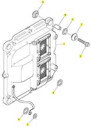
项目 零配件号码 新件号 描述
1 4620006 1 4620006 引擎控制组件ECM电脑控制模块
1 T412851 1 4620006 引擎控制组件ECM电脑控制模块
2 2314 H008 4 2314 H008 螺旋
3 2131 A008 1 2131 A008 垫圈
4 3311 A015 1 3311 A015 垫圈
5 3311 A015 1 3311 A015 垫圈
6 3311 A015 1 3311 A015 垫圈
7 3881 A005 4 3881 A005 架设
8 3313 A027 4 3313 A027 间隔器
9 3881 A005 4 3881 A005 架设
|
KENR9101 |
|
25 |
|
Electronic Troubleshooting |
|
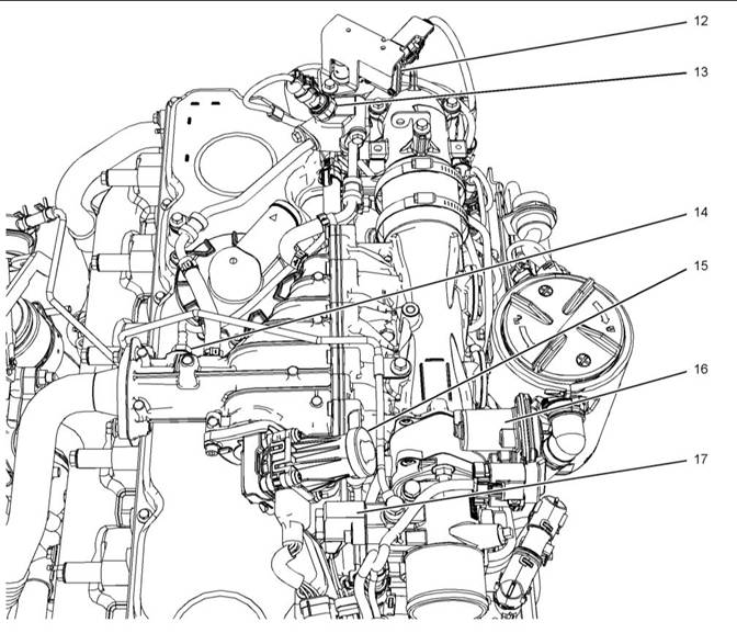
Illustration 11 |
|
g02313374 |
|
Close up views of sensor locations on the top of the engine |
|
(12) NOx Reduction System (NRS) temperaturesensor |
|
(14) NRS outlet pressure sensor (15) NRS valve with a position sensor |
|
(16) Engine intake throttle valve with a position sensor |
|
(13) NRS inlet pressure sensor |
|
(17) Wastegate regulator |
|
This document is printed from SPI². Not for RESALE |
![]()
![]()
|
26 |
|
KENR9101 |
|
Electronic Troubleshooting |
|
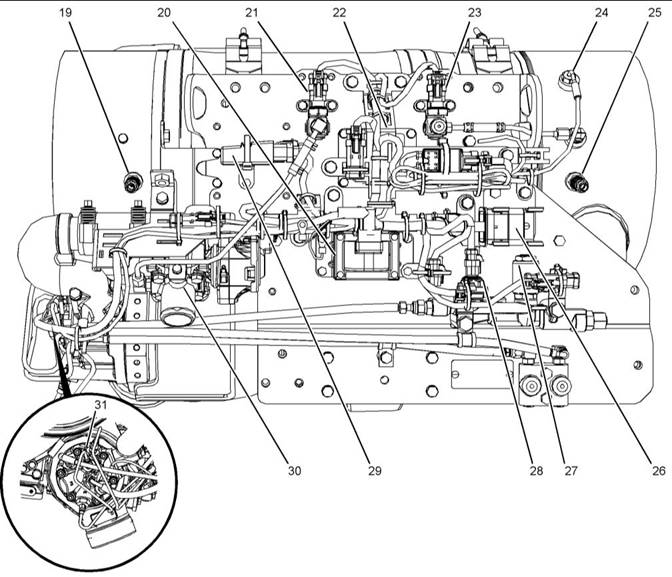
Illustration 12 |
|
g02854896 |
|
Sensors and components on a typical CEM |
|
(19) Soot antenna |
|
(23) Inlet pressure sensor for the DPF |
|
(28) ARD pilot fuel pressure sensor |
|
(20) Aftertreatment Regeneration Device (ARD) ignition coil (21) ARD air pressure sensor (22) Heater relay for the ARD nozzle |
|
(24) Inlet temperaturesensor for the DPF (25) Soot antenna (26) 40-pin harness connector (27) ARD pilot fuel control valve |
|
(29) AftertreatmentID module (30) ARD combustion air valve including a position sensor |
|
(31) Spark plug |
|
i05291450 |
|
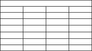
Table 5 |
|
Engine Wiring Information |
|
Color Codes for the Harness Wire |
|
Color Code |
|
Color |
|
Color Code |
|
Color |
|
BK BR |
|
Black |
|
BU |
|
Blue |
|
Harness Wire Identification |
|
Brown Red |
|
PU GY WH PK |
|
Purple Gray |
|
RD OR |
|
Perkins identifies all wires with 11 solid colors. The circuit number is stamped on the wire at a 25 mm (1 inch) spacing. Table 5 lists the wire colors and the color codes. |
|
Orange |
|
White Pink |
|
YL |
|
Yellow Green |
|
GN |
|
This document is printed from SPI². Not for RESALE |
![]()
![]()
|
KENR9101 |
|
27 |
|
Electronic Troubleshooting |
|
For example, a wire identification of X925-PK(Pink) on the schematic would signify a pink wire with the circuit number X925. X925-PK(Pink) identifies the power supply for the No. 1 injector. |
|
Note: Always replace a harness wire with the same gauge of wire and with the same color code. |
|
Note: In the following diagrams, “Px” signifies a plug and “Jx” signifies a jack. |
|
This document is printed from SPI². Not for RESALE |
![]()
|
28 |
|
KENR9101 |
|
Electronic Troubleshooting |
|
Schematic Diagrams |
|
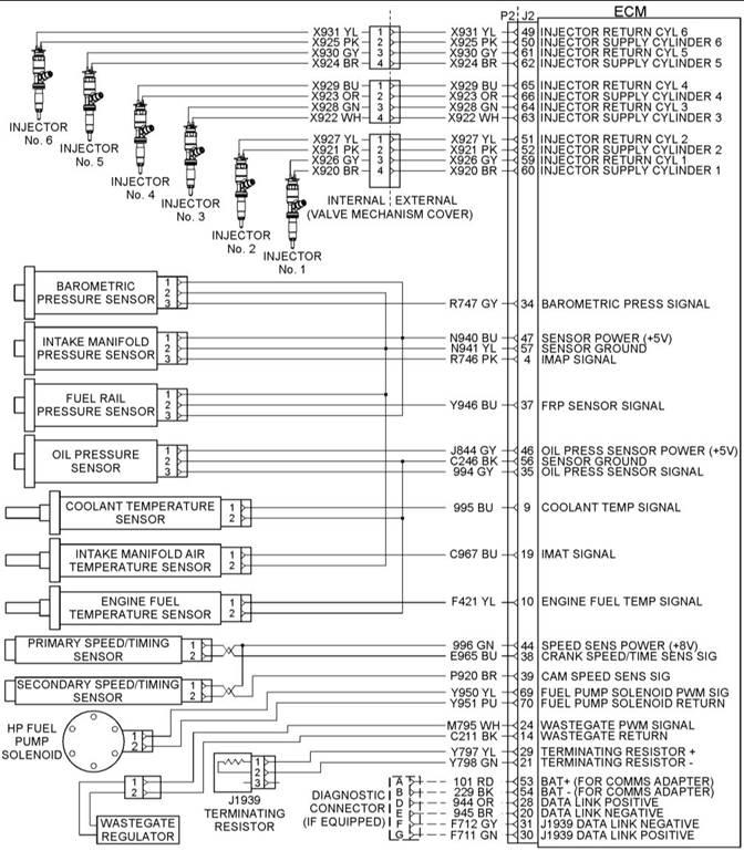
Illustration 13 |
|
g02175988 |
|
Schematic diagram of the engine connections to the J2 connector on the ECM |
|
This document is printed from SPI². Not for RESALE |
![]()
![]()
|
KENR9101 |
|
29 |
|
Electronic Troubleshooting |
|
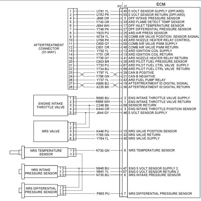
Illustration 14 |
|
g02362277 |
|
Schematic diagram of the NRS equipment |
|
This document is printed from SPI². Not for RESALE |
![]()
![]()
|
30 |
|
KENR9101 |
|
Electronic Troubleshooting |
|
Illustration 15 |
|
g02362256 |
|
Schematic diagram of the Clean Emissions Module (CEM) Sheet 1 of 2 |
|
This document is printed from SPI². Not for RESALE |