 English
 Espaol
 Franais
 阿拉伯
阿拉伯 中文
中文 Deutsch
 Italiano
 Português
 日本
日本 韩国
韩国 български
 hrvatski
 esky
esky Dansk
Dansk Nederlands
 suomi
suomi Ελληνικ
 印度
印度 norsk
norsk Polski
 Roman
Roman русский
 Svenska
Perkins珀金斯1306-E87TA86柴油发动机活塞及缸套供应商,Perkins珀金斯1306-E87TA86柴油发动机活塞及缸套技术价格规格咨询服务,Perkins珀金斯1306-E87TA86柴油发动机活塞及缸套零配件供应,Perkins珀金斯1306-E87TA86柴油发动机活塞及缸套售后服务中心,Perkins珀金斯1306-E87TA86柴油发动机活塞及缸套,Perkins珀金斯1306-E87TA86柴油发动机活塞及缸套详细的技术参数,

产品中心
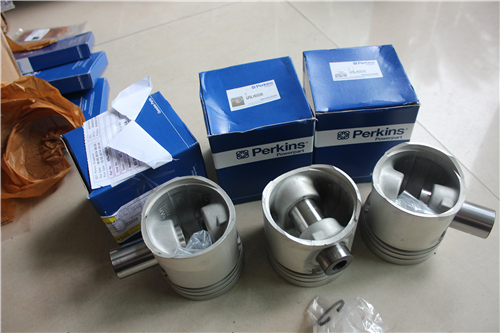
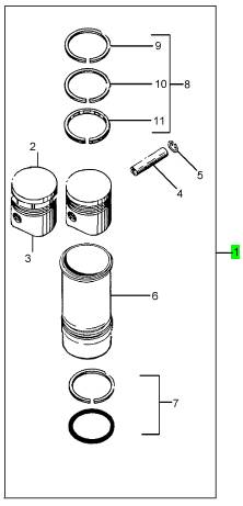
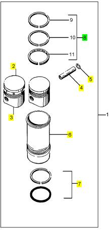
Perkins珀金斯1306-E87TA86柴油发动机活塞及缸套
详细描述
项目 零配件号码 新件号 描述
1 1841896 C94 6 1841896 C96 活塞及缸套装备
项目 零配件号码 新件号 描述
2 1836320 C2 1 1836320 C3 隆起
3 1833433 C1 1 1833433 C1 裙子
4 1874253 C1 1 1874253 C1 轴头销
5 1818702 C1 1 1818702 C1 CIRCLIP
6 1841326 C1 1 1875703 C2 缸套 - 滑移的精加工
7 1822322 C93 1 1822322 C93 密封装备
8 1830724 C92 1 1830724 C92 活塞环装备
项目 零配件号码 新件号 描述
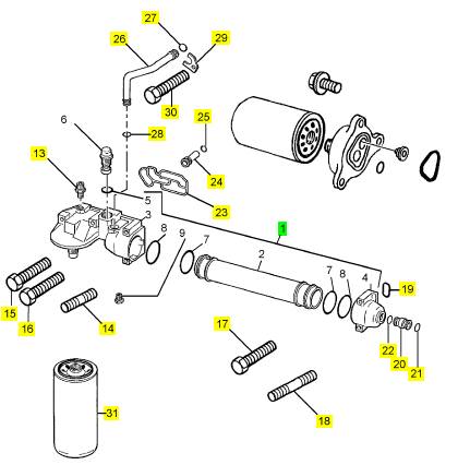
1 1841741 C92 1 1841741 C92 机油冷油器
1 1841739 C91 1 1841741 C92 机油冷油器
13 606819 C1 1 606819 C1 连接
14 1819931 C1 1 1819931 C1 图钉
15 1817958 C1 1 1817958 C1 螺旋
16 1817962 C1 3 1817962 C1 螺拴
17 1817962 C1 1 1817962 C1 螺拴
18 1819931 C1 1 1819931 C1 图钉
19 1830362 C1 1 1830362 C1 密封
20 1830190 C1 1 1830190 C1 管
21 1821098 C2 1 1821098 C2 密封O型圈
22 1821098 C2 1 1821098 C2 密封O型圈
23 1817849 C3 1 1817849 C3 密封垫片 - 滤油器的座
24 1815239 C3 1 1815239 C3 阀
25 1820907 C2 1 1820907 C2 密封O型圈
26 1817669 C1 1 1817669 C1 管
27 1821098 C2 1 1821098 C2 密封O型圈
28 1821098 C2 1 1821098 C2 密封O型圈
29 1817671 C1 1 1817671 C1 托架
30 1817812 C1 1 1817812 C1 公制的螺拴
31 26540244 1 26540244 滤油器
项目 零配件号码 新件号 描述
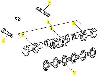
1 1 排气岐管
2 1814149 C2 1 1814149 C2 排气岐管
3 1821977 C2 1 1821977 C2 排气岐管
3 1821977 C1 1 1821977 C2 排气岐管
4 1814149 C2 1 1814149 C2 排气岐管
5 1825436 C1 1 1825436 C1 密封垫片 - 排气岐管
6 1821642 C3 4 1821642 C3 图钉
7 1817830 C1 12 1817830 C1 公制的螺拴
|
Peregrine EDi and 1300 Series EDi |
|
Lubrication system |
|
Lubricating oil pump |
|
Type. ... ... ... ... ... ... ... ... ... ... ... ... .. Differential rotor, the inner rotor fits into splines on the crankshaft nose Radial clearance of outer rotor to body ... ... ... ... ... ... ... ... ... ... ... ... ... ..0,470/0,622 mm (0.0185/0.0245 in) End-float outer rotor to body ... ... ... ... ... ... ... ... ... ... ... ... ... ... ... ... ... .. 0,066/0,142 mm (0.0026/0.0056 in) End-float of inner rotor to body ... ... ... ... ... ... ... ... ... ... ... ... ... ... ... ... ..0,066/0,142 mm (0.0026/0.0056 in) |
|
Oil pressure regulator valve |
|
Operating pressure.. ... ... ... ... ... ... ... ... ... ... ... ... ... ... ... ... ... ... ... ... ... .. 331 kPa (48 lbf/in ) 3,37 kgf/cm2 2 Position in the crankcase. ... ... ... ... ... ... ... ... ... ... ... ... ... ... ... ... Between the oil cooler and the crankcase |
|
Oil pressure relief valve |
|
Operating pressure.. ... ... ... ... ... ... ... ... ... ... ... ... ... ... ... ... ... ... ... ... ... ... 550 kPa (80 lbf/in ) 5,6 kgf/cm2 2 Position in the crankcase. ... ... ... ... ... ... ... ... ... ... ... ... ... ... ... ... ... ... ... ... ... ... ... ... inside the timing case |
|
Oil filter |
|
Type. ... ... ... ... ... ... ... ... ... ... ... ... ... ... ... ... ... ... ... ... ... ... ... ... ... ... ... ... ... ... ... ... ... ... ... ... ... .Canister By-pass valve .. ... ... ... ... ... ... ... ... ... ... ... ... ... ... ... ... ... ... ... ... ... ... ... ... ... ... ... ... .Fitted inside the filter Operating pressure.. ... ... ... ... ... ... ... ... ... ... ... ... ... ... ... ... ... ... ... ... ... ... ... ... ... ... ... 193 kPa (28 lb/in2) |
|
Oil temperature control valve |
|
Operating temperature range .. ... ... ... ... ... ... ... ... ... ... ... ... ... ... ... ... ... ... ... ...-54,4/148,9 °C (-65/300 °F) Valve closes at ... ... ... ... ... ... ... ... ... ... ... ... ... ... ... ... ... ... ... ... ... ... ... ... ... . 104,4/115,6 °C (235/240 °F) Valve opens at. ... ... ... ... ... ... ... ... ... ... ... ... ... ... ... ... ... ... ... ... ... ... ... ... ... ... ... ... ... .. 121,1 °C (250 °F) Valve movement from closed to open (minimum) ... ... ... ... ... ... ... ... ... ... ... ... ... ... ... ... 9,53 mm (0.375 in) |
|
Pump gear |
|
Backlash.. ... ... ... ... ... ... ... ... ... ... ... ... ... ... ... ... ... ... ... ... ... ... ... ... ..0,140/0,256 mm (0.0055/0.0101 in) End-float .. ... ... ... ... ... ... ... ... ... ... ... ... ... ... ... ... ... ... ... ... ... ... ... ... ... ... ... 0,45/1,22 mm (0.018/0.48 in) |
|
Fuel system |
|
Sensor for injection control pressure |
|
Operating temperature range .. ... ... ... ... ... ... ... ... ... ... ... ... ... ... ... ... ...-40 °C to 125 °C (-40 °F to 257 °F) Maximum flow rate .. ... ... ... ... ... ... ... ... ... ... ... ... ... ... .17,5 litres/min (4.62 US gals/min) 3.85 UK gals/min |
|
Maximum operating pressure: |
|
WK, WL, WM, and WN ... ... ... ... ... ... ... ... ... ... ... ... ... ... ... ... ... ... ... ... ... ... ... ... . 20,7 MPa (3000 lbf/in2) WP, WQ, WR and WS. ... ... ... ... ... ... ... ... ... ... ... ... ... ... ... ... ... ... ... ... ... ... ... ... . 23,5 MPa (3400 lbf/in2) |
|
Fuel filter |
|
Type. ... ... ... ... ... ... ... ... ... ... ... ... ... ... ... ... ... ... ... ... ... ... ... ... ... ... ... ... ... ... ... ... .Canister and strainer |
|
Nozzles |
|
Type. ... ... ... ... ... ... ... ... ... ... ... ... ... ... ... ... ... ... ... ... ... ... ... ... ... ... ... ... ... ... ... ... ... ... ... ... ...Multi hole Opening pressure ... ... ... ... ... ... ... ... ... ... ... ... ... ... ... ... ... ... ... ... ... ... . 24/124 MPa (3500/18000 lbs/in2) |
|
Fuel valve (fitted in the supply manifold) |
|
Opening pressure ... ... ... ... ... ... ... ... ... ... ... ... ... ... ... ... ... ... ... ... ... ... ... ... ... ... ... ... 414 kPa (60 lb/in2) |
|
Workshop Manual, TPD 1353E, Issue 3 |
|
17 |
|
This document has been printed from SPI². Not for Resale |
![]()
![]()
|
2 |
|
Peregrine EDi and 1300 Series EDi |
|
Cooling system |
|
Coolant pump |
|
Type... ... ... ... ... ... ... ... ... ... ... ... ... ... ... ... ... ... ... ... ... ... ... ... ... ... ... ... ... ... ... ... ... Belt driven, impeller |
|
Coolant filter |
|
Type... ... ... ... ... ... ... ... ... ... ... ... ... ... ... ... ... ... ... ... ... ... ... ... ... ... ... ... ... ... ... ... ... ... ... ... ... .. Canister Quantity.. ... ... ... ... ... ... ... ... ... ... ... ... ... ... ... ... ... ... ... ... ... ... ... ... ... ... ... ... ... ... ... ... ... ... ... ... ... ... ..1 |
|
Thermostat |
|
Starts to open: |
|
WK, WL, WM, and WN .. ... ... ... ... ... ... ... ... ... ... ... ... ... ... ... ... ... ... ... ... ... ... ... ... .82/85 °C (180/185 °F) ° WP, WQ, WR, and WS .. ... ... ... ... ... ... ... ... ... ... ... ... ... ... ... ... ... ... ... ... ... ... ... ... .86/89 C (187/192 °F) |
|
Fully open: |
|
WK, WL, WM, and WN .. ... ... ... ... ... ... ... ... ... ... ... ... ... ... ... ... ... ... ... ... ... ... ... ... ... ... ... .94 °C (202 °F) WP, WQ, WR, and WS .. ... ... ... ... ... ... ... ... ... ... ... ... ... ... ... ... ... ... ... ... ... ... ... ... ... ... ... .96 °C (205 °F) |
|
Flywheel and housing |
|
Flywheel |
|
Alignment... ... ... ... ... ... ... ... ... ... ... ... ... ... ... .0,18 mm (0.007 in) measured at a radius of 178 mm (7.0 in) Face run-out (clutch applications, ‘pot’ type)... ... ... ... ... ..0,165 mm (0.0065 in) measured at a radius of 165,1 mm (6.5 in) Face run-out (clutch cover plate). ... ... ... ... ... ... ... ... ... ... 0,19 mm (0.0075 in) measured at a radius of 190,5 mm (7.5 in) Face run-out (clutch applications, flat) ... ... ... ... ... ... ... ... ... ... ... ...0,2 mm (0.008 in) measured at clutch mounting holes Radial run-out of clutch pilot bore (internal diameter of ‘pot’ flywheel) - ‘pot’ type flywheel for clutch applications. ... ... ... ... ..0,13 mm (0.005 in) |
|
Flywheel housing |
|
Alignment... ... ... ... ... ... ... ... ... ... ... ... ... ... ... ... ... ... .SAE1 0,30 mm (0.012 in), SAE2 0,28 mm (0.011 in) Run-out .. ... ... ... ... ... ... ... ... ... ... ... ... ... ... ... ... ... ... .SAE1 0,30 mm (0.012 in), SAE2 0,28 mm (0.011 in) |
|
Electrical equipment |
|
Alternators |
|
Make and type ... ... ... ... ... ... ... ... ... ... ... ... ... ... ... ... ... ... ... ... ... ... ... ... ... ... ... ... ... ... ... . Lucas AC5RS Ratings: |
|
Lucas . ... ... ... ... ... ... ... ... ... ... ... ... ... ... ... ... ... ... ... ... ... ... ... ... ... ... ... ... ... ... ... ...12V/60A or 24V/55A |
|
Starter motors |
|
Make and type ... ... ... ... ... ... ... ... ... ... ... ... ... ... ... ... ... ... ... ... ... ... ... ... ... ... . Lucas S115, Lucas PE129 Ratings: |
|
Lucas . ... ... ... ... ... ... ... ... ... ... ... ... ... ... ... ... ... ... ... ... ... ... ... ... ... ... ... ... ... ... 12V/4.25kW or 24V/6kW |
|
18 |
|
Workshop Manual, TPD 1353E, Issue 3 |
|
This document has been printed from SPI². Not for Resale |
![]()
![]()
|
2 |
|
Peregrine EDi and 1300 Series EDi |
|
Recommended torque settings |
|
Notes: |
|
l The torque tensions below apply to components lubricated lightly with clean engine oil before they are fitted. |
|
l The setscrew for the upper idler gear is supplied with a sealant on its thread. Do not put lubricating oil on the thread of this setscrew. |
|
Standard torques |
|
Flanged head fasteners |
|
Non-flanged head fasteners |
|
Thread size |
|
Spanner size |
|
Spanner size mm |
|
Nm |
|
lbf ft |
|
kgf m |
|
Nm |
|
lbf ft |
|
kgf m |
|
mm |
|
M6 x 1 M8 x 1,25 M10 x 1,5 M12 x 1,75 M16 x 2 |
|
11 24 |
|
8 18 |
|
1,1 2,5 |
|
8 |
|
8 |
|
6 15 |
|
0,8 2,1 |
|
10 13 16 18 24 |
|
10 13 15 21 |
|
20 |
|
49 |
|
36 |
|
5,0 |
|
41 |
|
30 |
|
4,1 |
|
83 |
|
61 |
|
8,4 |
|
69 |
|
51 |
|
7,1 |
|
209 |
|
154 |
|
21,3 |
|
174 |
|
128 |
|
17,7 |
|
Specific torques |
|
Description |
|
Nm |
|
lbf ft |
|
kgf m |
|
Aspiration system |
|
Setscrew, breather pipe, bottom Setscrew, breather pipe, top |
|
49 83 66 23 13 |
|
36 61 49 17 9.6 |
|
5,0 8,4 |
|
Setscrews, turbocharger to exhaust manifold |
|
6,8 |
|
Setscrews, turbocharger compressor housing to backplate Setscrews, turbocharger turbine housing to bearing housing Auxiliary equipment |
|
2,35 1,3 |
|
Nut, air compressor drive gear |
|
149 115 62 |
|
110 85 |
|
15,21 11,9 6,4 |
|
Setscrews, air compressor mounting bracket to engine Setscrews, air compressor to engine Setscrews, air compressor to mounting bracket Cooling system |
|
46 |
|
66 |
|
49 |
|
6,7 |
|
Setscrews, coolant filter flange to timing case Setscrews, fan drive |
|
26 22 7 |
|
19 16 |
|
2,6 2,2 0,8 5,1 0,8 0,8 |
|
Setscrews, fan drive pulley |
|
5.5 37 |
|
Setscrews, fan belt tensioner to timing case Setscrews, coolant pump pulley |
|
50 7 |
|
5.5 5.5 |
|
Fasteners, coolant pump to timing case cover Crankshaft assembly |
|
7 |
|
Setscrews, main bearings |
|
See Operation 5-8 |
|
Setscrews, main bearings (engine serial number 850000 or more) Setscrews, pulley / damper assembly Setscrews, rear oil seal housing to cylinder block Cylinder head assembly |
|
See Operation 5-8 |
|
217 24 |
|
100 18 |
|
22,0 2,5 |
|
Setscrews, cylinder head |
|
See Operation 3-9 |
|
Setscrews, engine lift brackets |
|
60 81 18 27 |
|
44 60 13 20 |
|
6,0 8,3 1,8 2,8 |
|
Setscrews, exhaust manifold to cylinder head Setscrews, rocker cover |
|
Setscrews, supply manifold to cylinder head Flywheel and flywheel housing Setscrews, flywheel |
|
136 108 |
|
100 80 |
|
13,8 11,0 |
|
Setscrews, flywheel housing |
|
Workshop Manual, TPD 1353E, Issue 3 |
|
19 |
|
This document has been printed from SPI². Not for Resale |
![]()
![]()
![]()


|
2 |
|
Peregrine EDi and 1300 Series EDi |
|
Description |
|
Nm |
|
lbf ft |
|
kgf m |
|
Fuel system Banjo bolt, fuel return pipe |
|
35 42 42 27 6 |
|
26 31 31 20 4 |
|
3,6 4,3 4,3 2,8 0,6 3,6 1,4 1,8 2,8 |
|
Delivery valve assembly, to lift pump End nut, lift pump |
|
Lock nut, for the adjustment screw of the return valve Nuts, fuel lift pump to high-pressure pump Return valve, to supply manifold |
|
35 14 18 27 |
|
26 10 13 20 |
|
Setscrew, injector unit |
|
Setscrews, filter head to cylinder block Union nut, fuel return pipe |
|
Lubrication system, low-pressure Setscrews, oil cooler to cylinder block Setscrews, oil strainer and suction pipe Setscrews, sump |
|
26 20 23 68 34 |
|
19 15 17 50 25 |
|
2,6 2,1 2,4 7,0 3,5 |
|
Plug, sump |
|
Valve, oil temperature / pressure control (fitted in the oil cooler) Lubrication system, high-pressure Drain plug, supply manifold |
|
81 6 |
|
60 4.5 26 19 95 20 19 |
|
8,3 0,6 3,6 2,6 13,1 2,8 2,6 |
|
End nut, to secure the solenoid to the regulator valve Regulator valve for injection control pressure, to pump Sensor for injection control pressure, to supply manifold Setscrews, drive gear to pump |
|
35 26 129 27 26 |
|
Setscrews, high-pressure pump to timing case Union nut, high-pressure hose from pump to supply manifold Pistons and connecting rod assemblies Setscrews, connecting rods |
|
157 |
|
115 |
|
15,9 |
|
Timing case and drive assembly Setscrews, camshaft thrust plate |
|
26 26 |
|
19 19 |
|
2,6 2,6 |
|
Setscrews, timing case backplate Setscrews, timing case cover |
|
22 |
|
16 |
|
2,2 |
|
Setscrews, timing plate to camshaft gear Setscrew, lower idler gear |
|
7 |
|
5 |
|
0,7 |
|
637 332 |
|
470 245 |
|
65,6 33,9 |
|
Setscrew, upper idler gear |
|
20 |
|
Workshop Manual, TPD 1353E, Issue 3 |
|
This document has been printed from SPI². Not for Resale |
![]()
![]()

|
Peregrine EDi and 1300 Series EDi |
|
3 |
|
Cylinder head assembly |
|
3 |
|
General description |
|
All Peregrine EDi and the 1300 Series EDi engines have the inlet manifold integral with the rocker cover. The rocker cover also contains the engine breather assembly. |
|
In a diesel engine there is little carbon deposit and for this reason the number of hours run is no indication of when to overhaul a cylinder head assembly. The factors that indicate when an overhaul is necessary are how easily the engine starts and its general performance. |
|
The cylinder head assembly has two valves fitted for each cylinder, each fitted with a single valve spring, a valve seal assembly and a valve rotator. |
|
Valve seat inserts and valve guides are fitted in the cylinder head for the inlet valves and the exhaust valves. The valve seat inserts and the valve guides can be renewed. |
|
The face angle of the inlet valves and seats is 30°, and is 45° on the exhaust valves and seats. |
|
Sleeves are fitted in the cylinder head to remove heat from the fuel injector units and to seal them from the coolant. |
|
Workshop Manual, TPD 1353E, Issue 3 |
|
21 |
|
This document has been printed from SPI². Not for Resale |
![]()
![]()
|
3 |
|
Peregrine EDi and 1300 Series EDi |
|
Rocker cover |
|
To remove |
|
Operation 3-1 |
|
1 Remove the pipe for the air inlet from the rocker cover. |
|
2 Remove the setscrews that retain the engine breather pipe, and remove the pipe. |
|
3 Disconnect the wiring loom (A1) for the fuel injector units, at the rocker cover electrical connector (A2). |
|
4 Press the four tags (B1) that secure the rocker cover electrical connector for the wiring loom to the rocker cover, and push the connector into the rocker cover. |
|
1 |
|
2 |
|
1 |
|
A |
|
B |
|
W203/1 |
|
W203/2 |
|
5 Remove the 13 setscrews (C) that retain the rocker cover. |
|
6 Lift carefully the rocker cover and tilt it away from the exhaust manifold. Ensure that the electrical connector for the wiring loom is free from the rocker cover then remove the rocker cover from the engine. |
|
7 Remove the rocker cover gasket from the cylinder head. |
|
C |
|
W205 |
|
22 |
|
Workshop Manual, TPD 1353E, Issue 3 |
|
This document has been printed from SPI². Not for Resale |
![]()
![]()
![]()
![]()

|
3 |
|
Peregrine EDi and 1300 Series EDi To fit |
|
Operation 3-2 |
|
Special requirements Consumable products |
|
Description |
|
Part number |
|
POWERPART Silicon rubber sealant |
|
1861108 |
|
1 Clean the cylinder head and the rocker cover. |
|
2 Renew the elements of the engine breather, if necessary, see Operation 3-3. 3 Renew the gasket for the rocker cover, if necessary. |
|
4 Fit a new ‘O’ ring into the rocker aperture for the electrical connector. |
|
5 Hold the rocker cover over the engine and push the rocker cover electrical connector for the wiring loom of the fuel injector units into its hole in the rocker cover. Ensure that the four tags (A1) engage on the rocker cover. |
|
6 Fit the rocker cover, fit and tighten the 13 setscrews (B) to 18 Nm (13 lbf ft) 1,8 kgf m. |
|
1 |
|
A |
|
B |
|
W203/2 |
|
W205 |
|
7 Connect the wiring loom (C1) for the fuel injector units, at the rocker cover electrical connector (C2). 8 Fit a new ‘O’ ring onto the breather tube. |
|
9 Apply clean lubricating oil to the ‘O’ ring. |
|
10 Fit the breather pipe into the cover. |
|
11 Fit and tighten the top and bottom setscrews of the breather tube. |
|
1 |
|
2 |
|
C |
|
W203/1 |
|
Workshop Manual, TPD 1353E, Issue 3 |
|
23 |
|
This document has been printed from SPI². Not for Resale |
![]()
![]()
![]()
![]()


|
3 |
|
Peregrine EDi and 1300 Series EDi |
|
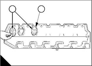
Engine breather elements |
|
To renew |
|
Operation 3-3 |
|
1 Remove the rocker cover, see Operation 3-1. |
|
2 Remove and discard the breather elements (A1) from their recesses (A2) in the rocker cover. 3 Clean the rocker cover. Ensure that the recesses are clean. 4 Fit a new breather element into each recess. |
|
5 Fit the rocker cover, see Operation 3-2. |
|
1 |
|
2 |
|
A |
|
W200/2 |
|
24 |
|
Workshop Manual, TPD 1353E, Issue 3 |
|
This document has been printed from SPI². Not for Resale |
![]()
![]()
![]()
![]()
|
3 |
|
Peregrine EDi and 1300 Series EDi |
|
Rocker assembly |
|
To remove |
|
Operation 3-4 |
|
Warning! Do not drain the coolant while the engine is still hot and the system is under pressure because dangerous hot coolant can be discharged. |
|
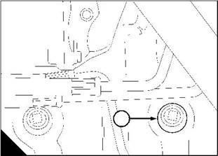
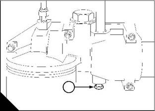
1 Remove the rocker cover, see Operation 3-1. |
|
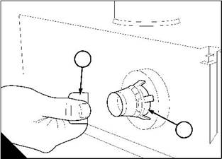
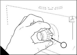
2 Remove the drain plug (A1) from the side of the cylinder block (behind the high-pressure pump), and the drain plug (B1) from the lubricating oil cooler in order to drain the engine. Open the tap or remove the drain plug at the bottom of the radiator in order to drain the radiator. If the radiator does not have a tap or drain plug, disconnect the hose at the bottom of the radiator. |
|
1 |
|
1 |
|
A |
|
B |
|
W005 |
|
W006 |
|
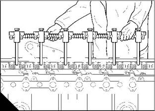
3 Loosen the adjustment screws on the rocker levers one turn (C). |
|
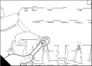
4 Release the rocker shaft setscrews evenly and gradually in the sequence 1-3-5-2-4-6, from the front of the engine, to avoid damage to the rocker assembly. |
|
5 Remove the rocker assembly, complete with setscrews and washers (D). |
|
C |
|
D |
|
W202 |
|
W206 |
|
Workshop Manual, TPD 1353E, Issue 3 |
|
25 |
|
This document has been printed from SPI². Not for Resale |
![]()
![]()
![]()
![]()
|
3 |
|
Peregrine EDi and 1300 Series EDi |
|
To fit |
|
Operation 3-5 |
|
1 Put the push rods and the rocker shaft assembly in position. Check that the push rods fit correctly in the sockets of the tappets. Check that the ends of the adjustment screws fit correctly in the sockets of the push rods. |
|
2 Inspect the cylinder head setscrews for damage and excessive wear. Renew any setscrews that are damaged or excessively worn. |
|
3 Lightly lubricate the threads and the thrust faces of the cylinder head setscrews with clean engine lubrication oil. |
|
Warning! Ensure that there is no lubricating oil in the holes for the cylinder head setscrews. If there is oil in these holes, the cylinder block could be damaged by hydraulic pressure when the setscrews are tightened. |
|
4 Engage all the setscrews in their correct positions, except the setscrews at each end of the shaft, and tighten them finger tight. |
|
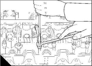
5 Ensure that the rocker shaft is in the correct position when the setscrews are tightened. To do this: |
|
l Put a 0,13 mm (0.005 in) feeler gauge (A2) between the rocker lever (A3) for the inlet valve of number one cylinder and the first mounting bracket (A1) of the rocker shaft |
|
l Put another 0,13 mm (0.005 in) feeler gauge between the rocker lever for the exhaust valve of number six cylinder and the last bracket of the rocker shaft |
|
l Fit the end setscrews, and tighten them finger tight. |
|
6 Tighten the setscrews in the correct sequence and to the correct torque, see Operation 3-9. Check for free movement of the first and last rocker lever. |
|
7 Remove the two feeler gauges. |
|
8 Check the valve tip clearances, see Operation 3-21. 9 Fit the rocker cover, see Operation 3-2. 10 Fill the cooling system. |
|
1 |
|
2 |
|
3 |
|
A |
|
W111 |
|
26 |
|
Workshop Manual, TPD 1353E, Issue 3 |
|
This document has been printed from SPI². Not for Resale |