 English
 Espaol
 Franais
 阿拉伯
阿拉伯 中文
中文 Deutsch
 Italiano
 Português
 日本
日本 韩国
韩国 български
 hrvatski
 esky
esky Dansk
Dansk Nederlands
 suomi
suomi Ελληνικ
 印度
印度 norsk
norsk Polski
 Roman
Roman русский
 Svenska
Perkins珀金斯1306-E87TA86柴油发动机配件手册供应商,Perkins珀金斯1306-E87TA86柴油发动机配件手册技术价格规格咨询服务,Perkins珀金斯1306-E87TA86柴油发动机配件手册零配件供应,Perkins珀金斯1306-E87TA86柴油发动机配件手册售后服务中心,Perkins珀金斯1306-E87TA86柴油发动机配件手册,Perkins珀金斯1306-E87TA86柴油发动机配件手册详细的技术参数,

产品中心
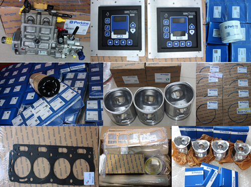
Perkins珀金斯1306-E87TA86柴油发动机配件手册
详细描述
项目 零配件号码 新件号 描述
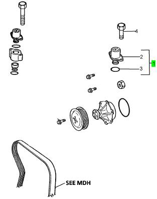
1 1830256 C93 1 1830256 C93 恒温节温器组合
1 1830256 C91 1 1830256 C93 恒温节温器组合
1 1830256 C92 1 1830256 C93 恒温节温器组合
4 1817812 C1 2 1817812 C1 公制的螺拴
项目 零配件号码 新件号 描述
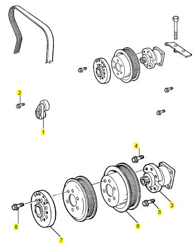
1 1830033 C2 1 1830033 C2 张紧轮臂
2 1817993 C1 1 1817993 C1 公制的螺拴
3 1822050 C93 1 1822050 C93 FANDRIVE
4 1817958 C1 2 1817958 C1 螺旋
5 1818230 C1 2 1818230 C1 公制的螺拴
6 1820309 C1 1 1820309 C1 风扇皮皮带轮
7 1820823 C1 1 1820823 C1 间隔器
8 1817978 C1 6 1817978 C1 螺拴
项目 零配件号码 新件号 描述
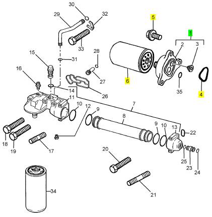
1 1827689 C91 1 1827689 C91 滤油器座
4 1820353 C1 1 1820353 C1 密封O型圈
5 1817957 C1 3 1817957 C1 公制的螺拴
6 26550001 1 26550001 水过滤器
项目 零配件号码 新件号 描述
1 1820465 C4 1 1820465 C4 正时齿轮盖
1 1820465 C3 1 1820465 C4 正时齿轮盖
2 1842909 C1 1 1842909 C1 密封 - 正时齿轮箱盖
2 1818717 C5 1 1842909 C1 密封垫片
3 1820920 C3 1 1820920 C3 密封O型圈
3 1820920 C2 1 1820920 C3 O 圈
4 1818716 C5 1 1818716 C5 密封
4 1818716 C4 1 1818716 C5 密封垫片
5 1 O 圈
6 1820878 C2 1 1820878 C2 密封O型圈
7 1817957 C1 1 1817957 C1 公制的螺拴
8 1817958 C1 8 1817958 C1 螺旋
9 1817959 C1 5 1817959 C1 公制的螺拴
10 1817960 C1 6 1817960 C1 公制的螺拴
11 1 指针
12 1826335 C92 1 1826335 C92 时间安排箱
12 1826335 C91 1 1826335 C92 定时齿轮箱
15 1833386 C1 1 1833386 C1 阀
16 1820907 C2 1 1820907 C2 密封O型圈
17 1842910 C1 1 1842910 C1 密封 - 正时齿轮箱
17 1820416 C4 1 1842910 C1 密封垫片 - 正时齿轮箱
18 1 螺旋
19 40050 R1 9 40050 R1 螺帽
20 1822121 C2 9 1822121 C2 公制的螺拴

项目 零配件号码 新件号 描述
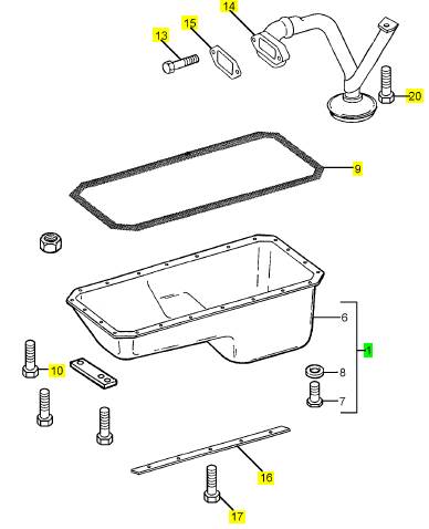
1 1819018 C93 1 检查历史 油底壳875522
5 1823278 C92 1 1823740 C93 油底壳 875523
9 1826587 C1 1 1826587 C1 密封垫片 -油底壳
10 1817812 C1 22 1817812 C1 公制的螺拴
11 1823275 C1 14 1823275 C1 公制的螺拴
12 1823967 C1 22 1823281 C1 公制的螺拴
13 1823275 C1 8 1823275 C1 公制的螺拴
14 1834491 C1 1 1834491 C1 管组合
15 1816722 C2 1 1816722 C2 密封垫片
16 1879473 C1 2 1879473 C1 除
16 1822523 C1 2 1879473 C1 除
17 1823281 C1 8 1823281 C1 螺拴
18 1817812 C1 1 1817812 C1 公制的螺拴
19 1829820 C1 1 1829820 C1 公制的螺拴
20 1835385 C1 1 1835385 C1 螺拴
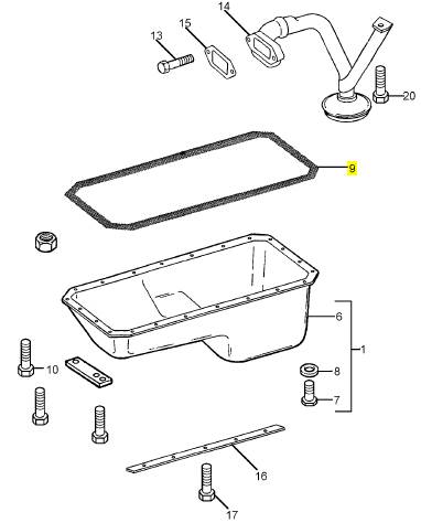
项目 零配件号码 新件号 描述
2 1 油底壳
3 1822053 C1 1 检查历史 栓塞
4 1822054 C1 1 1822054 C1 密封垫片 -油底壳
9 1816593 C1 1 1816593 C1 密封垫片 -油底壳 1.5 盎斯。 管
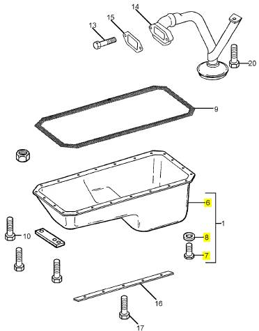
项目 零配件号码 新件号 描述
6 1 油底壳
7 1822053 C1 1 检查历史 栓塞
8 1822054 C1 1 1822054 C1 密封垫片 -污水坑
|
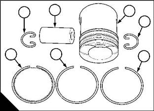
To dismantle and assemble (one-piece pistons) |
|
Operation 4-6 |
|
To dismantle |
|
Note: Mark the components to ensure that they are returned to the correct cylinder. 1 Remove the piston rings (B5, B6 and B7), see Operation 4-11. |
|
2 Remove the circlips (B1 and B4) that retain the gudgeon pin (B2) and push the gudgeon pin out of the piston (B3) by hand. |
|
3 Separate the connecting rod from the piston. To assemble |
|
1 Clean the bore of the small end bush and lubricate it with clean engine lubricating oil. |
|
2 Fit a new circlip (B1) in the circlip groove of one of the gudgeon pin bosses. Ensure that it fits correctly in the groove. |
|
Caution: If the original piston is used, ensure that it is assembled to the correct connecting rod and that it is used in the original cylinder. |
|
3 With the piston (B3) upside down, put the connecting rod in position. Ensure that the short side of the connecting rod (A1) is on the same side as the “camside” mark (B) on the piston crown. |
|
4 Lubricate the gudgeon pin and the gudgeon pin bosses in the piston with clean engine lubricating oil. 5 Push in the gudgeon pin (B2) towards the circlip. |
|
6 Fit the other new circlip (B4) in the groove in the other gudgeon pin boss. Ensure that it fits correctly in the groove. |
|
7 Fit the piston rings, see Operation 4-11. |
|
2 |
|
3 |
|
1 |
|
4 5 |
|
1 |
|
7 |
|
6 |
|
A |
|
B |
|
W084 |
|
W080 |
|
58 |
|
Workshop Manual, TPD 1353E, Issue 3 |
|
This document has been printed from SPI². Not for Resale |
![]()
![]()
![]()
![]()
|
4 |
|
Peregrine EDi and 1300 Series EDi |
|
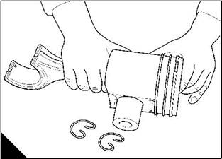
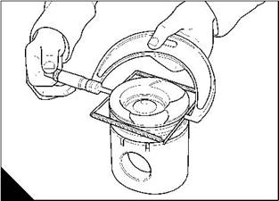
To dismantle and assemble (two-piece pistons) |
|
Operation 4-7 |
|
To dismantle |
|
Note: Mark the components to ensure that they are returned to the correct cylinder. Mark the piston skirt and the piston crown to ensure correct assembly. |
|
1 Remove the piston rings, see Operation 4-11. |
|
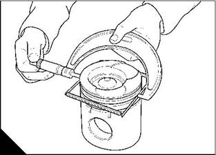
2 Remove the circlips that retain the gudgeon pin and push the gudgeon pin out of the piston by hand (A). 3 Separate the connecting rod from the piston. |
|
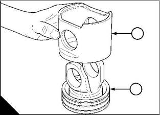
4 Remove the piston skirt (B1) from the piston crown (B2). |
|
To assemble |
|
1 Clean the bore of the small end bush and lubricate it with clean engine lubricating oil. |
|
2 Put the piston skirt (B1) on the piston crown (B2), ensure that the marks made earlier are aligned. |
|
3 Fit a new circlip (A) in the circlip groove of one of the gudgeon pin bosses. Ensure that it fits correctly in the groove. |
|
Caution: If the original piston is used, ensure that it is assembled to the correct connecting rod and that it is used in the original cylinder. |
|
4 With the piston upside down, put the connecting rod in position. Ensure that the short side of the connecting rod is on the same side as the “camside” mark on the piston crown. |
|
5 Lubricate the gudgeon pin and the gudgeon pin bosses in the piston with clean engine lubricating oil. 6 Push in the gudgeon pin towards the circlip. |
|
7 Fit the other new circlip in the groove in the other gudgeon pin boss. Ensure that it fits correctly in the groove. 8 Fit the piston rings, see Operation 4-11. |
|
1 |
|
2 |
|
A |
|
B |
|
W138 |
|
W086 |
|
Workshop Manual, TPD 1353E, Issue 3 |
|
59 |
|
This document has been printed from SPI². Not for Resale |
![]()
![]()
![]()
![]()
|
4 |
|
Peregrine EDi and 1300 Series EDi |
|
To inspect |
|
Operation 4-8 |
|
Special requirements |
|
Special tools |
|
Description |
|
Part number |
|
Piston groove gauges |
|
21825955 |
|
1 Check the piston for wear and other damage. |
|
2 Check that the piston rings move freely in their grooves and that the piston rings are not broken. 3 Remove the piston rings, see Operation 4-11. |
|
4 Clean the piston ring grooves and the piston rings. |
|
5 Fit the piston groove gauge 21825955 to the top compression ring groove, measure and record the overall diameter of the piston and the gauge (A). |
|
6 Fit the piston groove gauge 21825955 to the second compression ring groove, measure and record the overall diameter of the piston and the gauge (B) |
|
A |
|
B |
|
W049 |
|
W049/1 |
|
7 Fit a new oil control ring in its groove and check for wear of the ring groove with feeler gauges (C). |
|
8 Measure and record the diameter of the piston skirt (D). Measured at 90° from the gudgeon pin, at a point 27,43 mm (1.08 in) below the oil control ring. Refer to the relevant Data and dimensions for the "Piston rings" on page 12. |
|
C |
|
D |
|
W050 |
|
W087 |
|
60 |
|
Workshop Manual, TPD 1353E, Issue 3 |
|
This document has been printed from SPI². Not for Resale |
![]()
![]()
![]()
![]()
|
4 |
|
Peregrine EDi and 1300 Series EDi |
|
Connecting rod |
|
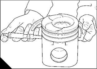
To inspect |
|
Operation 4-9 |
|
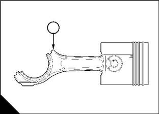
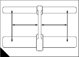
1 Check the connecting rod for distortion (A). |
|
Note: The large and small end bores must be square and parallel with each other within the limits of ± 0,127 mm (0.005 in) measured 127 mm (5.0 in) each side of the connecting rod axis on a test mandrel. |
|
2 Check the small end bush for wear or for other damage and renew it, if necessary. |
|
3 Check the fit of the gudgeon pin in the small end bush and check the gudgeon pin for wear. Refer to the relevant Data and dimensions for the "Gudgeon pins" on page 13. |
|
127mm 127mm |
|
(5in) |
|
(5in) |
|
± 0,127mm (0.005in) |
|
± 0,127mm (0.005in) |
|
A |
|
W025 |
|
Small end bush |
|
To remove and to fit |
|
Operation 4-10 |
|
1 Press out the old bush with a suitable adaptor. |
|
2 Clean the connecting rod bore and remove any sharp edges. |
|
3 Press in the new bush. Ensure that the lubrication hole in the bush is on the same side as, and is aligned with, the hole in the top of the connecting rod. |
|
4 The connecting rods on all of the engines have a small end that is wedge shaped. After the small end bush has been fitted, machine the bush to the shape of the small end and remove any sharp edges. |
|
Workshop Manual, TPD 1353E, Issue 3 |
|
61 |
|
This document has been printed from SPI². Not for Resale |
![]()
![]()
![]()
![]()
![]()
![]()
|
4 |
|
Peregrine EDi and 1300 Series EDi |
|
Piston rings |
|
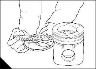
To remove and to fit |
|
Operation 4-11 |
|
Caution: Only increase the ring gaps enough to ensure that the ends of the rings do not damage the piston. |
|
To remove |
|
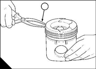
1 Remove the piston rings with a suitable ring expander (A1). |
|
To fit |
|
1 Use a suitable ring expander (A1) to fit the piston rings. Keep the rings with their relevant pistons, for correct assembly. |
|
2 Fit the coil spring and latch pin to the bottom groove in the piston. Fit the oil control ring over the coil spring. Ensure that the gap in the coil spring and the gap in the latch pin of the coil spring are 180° apart. |
|
1 |
|
A |
|
W088 |
|
62 |
|
Workshop Manual, TPD 1353E, Issue 3 |
|
This document has been printed from SPI². Not for Resale |
![]()
![]()
![]()
![]()
|
4 |
|
Peregrine EDi and 1300 Series EDi To inspect |
|
Operation 4-12 |
|
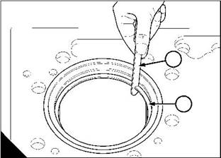
Caution: The coil spring must be fitted to the oil control ring when the gap is measured. 1 Clean all carbon from the top of the cylinder liners. |
|
2 Fit each piston ring (A2) in the top part of the cylinder liner, measure and record the ring gap with feeler gauges (A1). |
|
1 |
|
2 |
|
A |
|
W051 |
|
Workshop Manual, TPD 1353E, Issue 3 |
|
63 |
|
This document has been printed from SPI². Not for Resale |
![]()
![]()
![]()
![]()
|
This page is intentionally blank |
|
This document has been printed from SPI². Not for Resale |
|
Peregrine EDi and 1300 Series EDi |
|
5 |
|
Crankshaft assembly |
|
5 |
|
General description |
|
The crankshaft is a steel forging with seven main journals. All the crankshaft journals and the crank pins are induction hardened. |
|
End-float is controlled by thrust washers that are an integral part of the rear main bearing, and shall be referred to as thrust bearings in this manual. The area of the bearing surfaces of the seven main bearings is the same. All the main bearings have location tags. |
|
An integral damper, with a rubber insert is built into the crankshaft pulley. The location of the pulley / damper assembly is by a key in the crankshaft nose. The assembly is held in position by an interference fit, and by a retainer plate and three setscrews.The pulley / damper assembly must be heated before it is fitted on the crankshaft. |
|
The rear oil seal can be renewed without the removal of the flywheel housing. |
|
Workshop Manual, TPD 1353E, Issue 3 |
|
65 |
|
This document has been printed from SPI². Not for Resale |
![]()
![]()
|
5 |
|
Peregrine EDi and 1300 Series EDi |
|
Crankshaft pulley / damper assembly |
|
To remove |
|
Operation 5-1 |
|
Special requirements Special tools |
|
Description |
|
Part number |
|
Crankshaft pulley puller |
|
21825965 |
|
Note: Before removing the pulley / damper assembly check for alignment, see Operation 5-2. |
|
1 Drain the lubricating system. |
|
2 Remove the fan drive belt, see Operation 12-7. |
|
3 Release and remove the three setscrews (A) that hold the retainer plate of the pulley / damper assembly. 4 Remove the retainer plate (A). |
|
5 Use the puller 21825965 to remove the pulley / damper assembly (B). |
|
Note: It is recommended that whenever the pulley / damper assembly is removed, the wear sleeve and seals should be renewed. |
|
A |
|
B |
|
W089 |
|
W126 |
|
66 |
|
Workshop Manual, TPD 1353E, Issue 3 |