 English
 Espaol
 Franais
 阿拉伯
阿拉伯 中文
中文 Deutsch
 Italiano
 Português
 日本
日本 韩国
韩国 български
 hrvatski
 esky
esky Dansk
Dansk Nederlands
 suomi
suomi Ελληνικ
 印度
印度 norsk
norsk Polski
 Roman
Roman русский
 Svenska
Perkins珀金斯1306-E87TA86柴油发动机2873 K116启动马达供应商,Perkins珀金斯1306-E87TA86柴油发动机2873 K116启动马达技术价格规格咨询服务,Perkins珀金斯1306-E87TA86柴油发动机2873 K116启动马达零配件供应,Perkins珀金斯1306-E87TA86柴油发动机2873 K116启动马达售后服务中心,Perkins珀金斯1306-E87TA86柴油发动机2873 K116启动马达,Perkins珀金斯1306-E87TA86柴油发动机2873 K116启动马达详细的技术参数,

产品中心
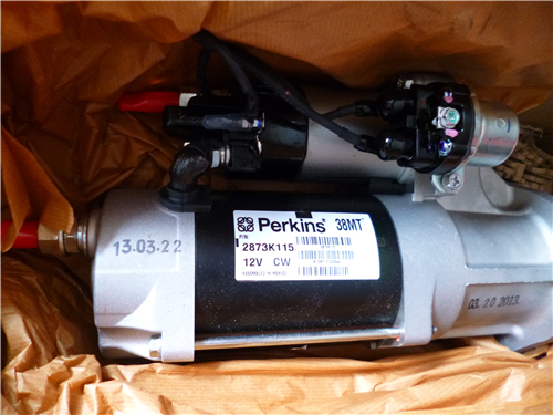
Perkins珀金斯1306-E87TA86柴油发动机2873 K116启动马达
详细描述
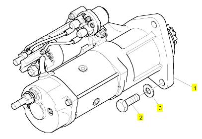
项目 零配件号码 新件号 描述
1 2873 K116 1 2873 K116 启动马达
2 0748663 3 0748663 螺旋
3 0920444 3 0920444 垫圈
|
Peregrine EDi and 1300 Series EDi To fit |
|
Operation 5-2 |
|
Special requirements Consumable products |
|
Description |
|
Part number |
|
POWERPART Silicone RTV sealing and jointing compound |
|
1861108 |
|
Warning! Use suitable gloves to protect the hands from heat. |
|
1 Heat the pulley / damper assembly. Do not exceed 198 °C (388 °F) WK, WL, WM, and WN. For WP, WQ, WR, and WS do not exceed 100 °C (212 °F). |
|
Caution: Do not try to fit a cold pulley / damper assembly as this will damage the crankshaft. |
|
2 Put the pulley assembly on the crankshaft, engage the drive key and push the pulley fully towards the rear. 3 Clean off the old sealant from the retainer plate and from the pulley / damper assembly. |
|
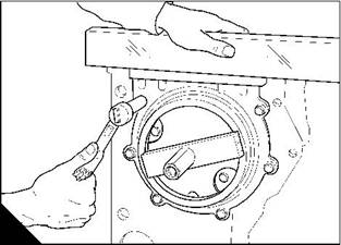
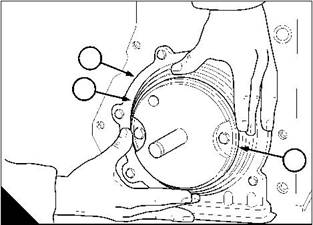
4 Put POWERPART Silicone RTV sealing and jointing compound on the inner face of the retainer plate and fit the retainer plate (A). |
|
5 Lubricate lightly the threads of the setscrews for the retainer plate with clean engine lubricating oil. 6 Fit and tighten the setscrews gradually and evenly to 136 Nm (100 lbf ft) 13,8 kgf m. 7 Fit the fan drive belt, see Operation 12-7. |
|
8 Fill the lubricating sump to the correct level with an approved lubricating oil, see Chapter 5 in the User’s Handbook. |
|
A |
|
W090 |
|
Workshop Manual, TPD 1353E, Issue 3 |
|
67 |
|
This document has been printed from SPI². Not for Resale |
![]()
![]()
![]()
![]()
|
5 |
|
Peregrine EDi and 1300 Series EDi |
|
To inspect |
|
Operation 5-3 |
|
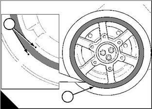
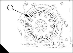
Clean the components and check for damage. The assembly must be renewed if: |
|
l There are cracks in the rubber (A2) l The rubber is damaged by oil |
|
l The component alignment marks (A1) exceed the tolerance in the relevant Data and dimensions for the "Crankshaft assembly" on page 14. |
|
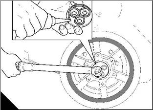
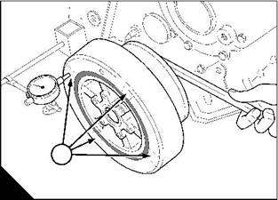
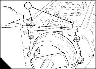
Measure and record damper alignment (B) at four places (B1) 90° apart on the damper face. Ensure that the crankshaft is at the same end of its axial movement for each measurement. This eliminates crankshaft end- float from the measurement. |
|
Before the pulley / damper assembly is removed from the crankshaft, measure and record the run-out of the damper mounting face on the crankshaft palm. |
|
Compare all the readings with the relevant Data and dimensions for the "Crankshaft assembly" on page 14. |
|
1 |
|
1 |
|
2 |
|
A |
|
B |
|
W020 |
|
W021 |
|
68 |
|
Workshop Manual, TPD 1353E, Issue 3 |
|
This document has been printed from SPI². Not for Resale |
![]()
![]()
![]()
![]()
|
5 |
|
Peregrine EDi and 1300 Series EDi |
|
Rear oil seal housing assembly |
|
To remove the oil seal housing |
|
Operation 5-4 |
|
Cautions: |
|
l Renew the rear oil seal and the wear sleeve as a unit, do not separate them. l The flywheel housing does not have to be removed to renew the rear oil seal. 1 Drain the lubricating oil. |
|
2 Remove the lubricating oil sump, see Operation 10-9. 3 Remove the drive components from the rear end of the engine. 4 Remove the flywheel, see Operation 13-1. |
|
5 Remove the rear oil seal, see Operation 5-6. |
|
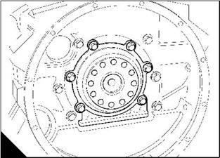
6 Remove the four setscrews that pass through the flange of the sump and into the bottom of the seal housing. 7 Remove the six setscrews that retain the seal housing to the cylinder block. |
|
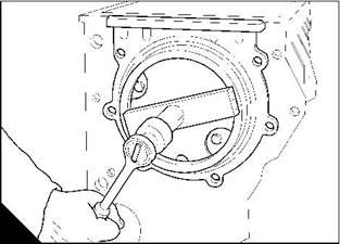
8 Remove the rear oil seal and housing assembly (A). Remove and discard the old oil seal gasket from between the housing and the cylinder block. |
|
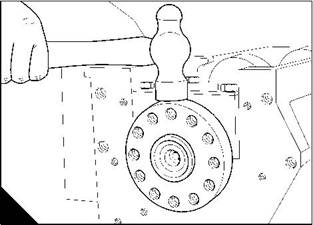
9 Hit carefully the outside diameter of the wear sleeve with a hammer to loosen the wear sleeve from the crankshaft (B). |
|
10 Remove the wear sleeve from the crankshaft. |
|
A |
|
B |
|
W045 |
|
W091 |
|
Workshop Manual, TPD 1353E, Issue 3 |
|
69 |
|
This document has been printed from SPI². Not for Resale |
![]()
![]()
![]()
![]()
![]()
|
5 |
|
Peregrine EDi and 1300 Series EDi |
|
To fit the oil seal housing |
|
Operation 5-5 |
|
Special requirements |
|
Special tools |
|
Description |
|
Part number |
|
Rear oil seal installer |
|
21825963 |
|
1 Clean the faces of the cylinder block, the oil seal housing and the crankshaft palm. 2 Fit the guide adaptor from tool 21825963 to the end of the crankshaft (A). 3 Fit a new seal (B1) to the oil seal housing face (B3). |
|
4 Put the housing (B2) into position on the engine, fit and tighten the setscrews finger tight. |
|
2 1 |
|
3 |
|
A |
|
B |
|
W092/1 |
|
W093 |
|
5 Fit the plate from tool 21825963 to the guide adaptor. Tighten the nut of the tool (C) until the plate comes into contact with the face of the housing. |
|
6 Use a straight edge to check that the seal housing is level with the cylinder block face (D). 7 Tighten the setscrews to 24 Nm (18 lbf ft) 2,5 kgf m. |
|
C |
|
D |
|
W048/1 |
|
W046 |
|
Continued |
|
70 |
|
Workshop Manual, TPD 1353E, Issue 3 |
|
This document has been printed from SPI². Not for Resale |
![]()
![]()
![]()
![]()


|
5 |
|
Peregrine EDi and 1300 Series EDi |
|
8 Cut off the excess seal length (E1) so that it is level with the face of the cylinder block. 9 Remove the tool 21825963. |
|
10 Fit the new rear oil seal / wear sleeve and the POSE seal, see Operation 5-6. 11 Fit the lubricating oil sump, see Operation 10-10. |
|
12 Fit the flywheel, see Operation 13-2. |
|
13 Fit the drive components to the rear end of the engine. |
|
14 Fill the lubricating oil sump to the correct level with an approved lubricating oil, see Chapter 5 in the User’s Handbook. |
|
1 |
|
E |
|
W047 |
|
Workshop Manual, TPD 1353E, Issue 3 |
|
71 |
|
This document has been printed from SPI². Not for Resale |
![]()
![]()
|
5 |
|
Peregrine EDi and 1300 Series EDi |
|
To renew the rear oil seal and wear sleeve assembly |
|
Operation 5-6 |
|
Special requirements Special tools |
|
Consumable products |
|
Description |
|
Part number ZTSE 4404 21825963 |
|
Description |
|
Part number |
|
Remover for the wear sleeve of the rear oil seal |
|
POWERPART Compound |
|
1861147 |
|
Rear oil seal installer |
|
Notes: |
|
l The oil seal housing does not have to be removed to renew the rear oil seal and wear sleeve assembly. l The flywheel housing does not have to be removed to renew the rear oil seal and wear sleeve assembly. l Renew the rear oil seal and the wear sleeve as a unit, do not separate them. 1 Drain the lubricating oil. |
|
2 Remove the drive components from the rear end of the engine. 3 Remove the flywheel, see Operation 13-1. |
|
Note: From engine number N1194039, types WP, WQ, WR and WS, a new rear oil seal assembly has been introduced that prevents the entry of debris from the environment. The seal includes a ‘Positive On-Shaft Excluder’ (P.O.S.E.), which extends the life of the seal. |
|
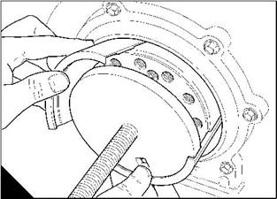
4 Use a suitable smooth tool to remove the POSE seal from the rear oil seal wear sleeve (A). 5 Fit two self-tapping screws (B2) into the front face (B1) of the oil seal. 6 Carefully lever the seal from the seal housing (B). |
|
Caution: Do not damage the seal housing or the crankshaft palm. |
|
1 |
|
2 |
|
A |
|
B |
|
W1386 |
|
W094 |
|
Continued |
|
72 |
|
Workshop Manual, TPD 1353E, Issue 3 |
|
This document has been printed from SPI². Not for Resale |
![]()
![]()
![]()
![]()
![]()

|
5 |
|
Peregrine EDi and 1300 Series EDi |
|
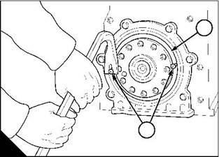
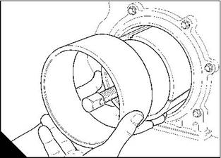
7 Fit the remover tool ZTSE 4404 (C) and (D). |
|
C |
|
D |
|
W226 |
|
W227 |
|
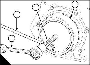
8 Fit a square headed lever (E1) into the 12,7 mm (0.5 in) hole in the front face of the remover tool (E3). |
|
9 Fit a spanner (E4) to the threaded rod (E2) of the remover tool. Hold the lever and tighten the threaded rod with the spanner to remove the wear sleeve. |
|
10 Discard the oil seal and wear sleeve. |
|
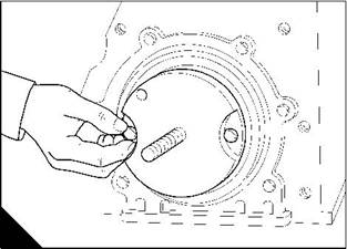
11 Clean the oil seal housing and the crankshaft palm. 12 Fit the guide adaptor (F) from tool 21825963 to the end of the crankshaft. |
|
13 Apply POWERPART Compound to the outer diameter of the oil seal and to the inner diameter of the wear sleeve. |
|
Caution: Fit the rear oil seal and the wear sleeve as a unit, do not separate them. |
|
3 |
|
2 |
|
1 |
|
4 |
|
E |
|
F |
|
W228 |
|
W092/1 |
|
Continued |
|
Workshop Manual, TPD 1353E, Issue 3 |
|
73 |
|
This document has been printed from SPI². Not for Resale |
![]()
![]()
|
5 |
|
Peregrine EDi and 1300 Series EDi |
|
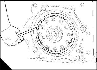
14 Put the oil seal and wear sleeve assembly (G1) into position on the guide adaptor (G3) from tool 21825963. |
|
15 Fit the plate from tool 21825963 to the guide adaptor. Tighten the nut of the tool until the plate comes into contact with the face of the housing (H). |
|
2 1 |
|
3 |
|
G |
|
H |
|
W093 |
|
W048 |
|
Note: When the plate from tool 21825963 comes into contact with the face of the seal housing, the oil seal and the wear sleeve are in their correct positions. |
|
16 Fit the new POS, E seal (J1) to the wear sleeve on the crankshaft palm by hand until it is fully in position. 17 Fit the flywheel, see Operation 13-2. |
|
18 Fit the drive components to the rear end of the engine. |
|
19 Fill the lubricating oil sump to the correct level with an approved lubricating oil, see Chapter 5 in the User’s Handbook. |
|
1 |
|
J |
|
W1385 |
|
74 |
|
Workshop Manual, TPD 1353E, Issue 3 |
|
This document has been printed from SPI². Not for Resale |
![]()
![]()
|
5 |
|
Peregrine EDi and 1300 Series EDi |
|
Crankshaft |
|
To remove |
|
Operation 5-7 |
|
Warning! Use lift equipment or obtain assistance to lift heavy engine components such as the flywheel housing, flywheel and crankshaft. |
|
1 Drain the lubricating oil and the coolant. |
|
2 Remove the lubricating oil sump, see Operation 10-9. 3 Remove the fan drive belt, see Operation 12-7. |
|
4 Remove the fan, see Operation 12-5. |
|
5 Remove the fan drive pulley and fan mounting, see Operation 12-6. 6 Remove the coolant pump, see Operation 12-4. |
|
7 Remove the pulley / damper assembly, see Operation 5-1. 8 Remove the alternator and its mounting bracket, see Operation 14-1. 9 Remove the compressor and its drive assembly, if one is fitted, see Operation 15-1. 10 Remove the timing case cover, see Operation 6-1. 11 Remove the high-pressure pump, see Operation 10-21. 12 Remove the timing case backplate, see Operation 6-5. 13 Remove the flywheel, see Operation 13-1. |
|
14 Remove the flywheel housing, see Operation 13-4. 15 Remove the rear oil seal housing assembly, see Operation 5-4. 16 Remove the lubricating oil suction pipe and strainer, see Operation 10-11. 17 Remove the lubricating oil pump, see Operation 10-12. |
|
18 Remove the big end bearing caps (A) from the connecting rods. Keep the shell-bearings and their shell- bearing caps together. |
|
190 |
|
4 |
|
5 |
|
190 |
|
A |
|
W082/1 |
|
Continued |
|
Workshop Manual, TPD 1353E, Issue 3 |
|
75 |
|
This document has been printed from SPI². Not for Resale |