 English
 Espaol
 Franais
 阿拉伯
阿拉伯 中文
中文 Deutsch
 Italiano
 Português
 日本
日本 韩国
韩国 български
 hrvatski
 esky
esky Dansk
Dansk Nederlands
 suomi
suomi Ελληνικ
 印度
印度 norsk
norsk Polski
 Roman
Roman русский
 Svenska
Perkins珀金斯1306-E87TA86柴油发动机1822102 C96惰轮传动机构供应商,Perkins珀金斯1306-E87TA86柴油发动机1822102 C96惰轮传动机构技术价格规格咨询服务,Perkins珀金斯1306-E87TA86柴油发动机1822102 C96惰轮传动机构零配件供应,Perkins珀金斯1306-E87TA86柴油发动机1822102 C96惰轮传动机构售后服务中心,Perkins珀金斯1306-E87TA86柴油发动机1822102 C96惰轮传动机构,Perkins珀金斯1306-E87TA86柴油发动机1822102 C96惰轮传动机构详细的技术参数,

产品中心
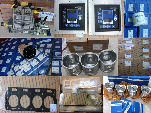
Perkins珀金斯1306-E87TA86柴油发动机1822102 C96惰轮传动机构
详细描述
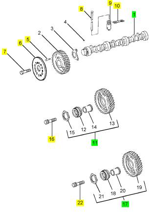
项目 零配件号码 新件号 描述
1 1830613 C94 1 1830613 C94 凸轮轴
1 1830613 C91 1 1830613 C94 凸轮轴
5 1817956 C1 2 1817956 C1 公制的螺拴
6 1824723 C1 1 1824723 C1 圆盘
7 1825464 C1 3 1825464 C1 螺旋
8 12 PUSHROD
9 12 挺杆
10 6 导入
11 1822102 C96 1 1822102 C96 惰轮传动机构
11 1822102 C95 1 1822102 C96 惰轮传动机构
16 1820287 C2 1 1820287 C2 螺拴
16 1820287 C1 1 1820287 C2 公制的螺拴
17 1822101 C96 1 1822101 C96 惰轮传动机构
17 1822101 C95 1 1822101 C96 惰轮传动机构
22 40055 R1 1 40055 R1 公制的螺拴
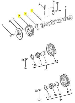
项目 零配件号码 新件号 描述
2 1823944 C92 1 1823944 C92 凸轮轴传动机构
3 1817545 C1 1 检查历史 板
4 218211 1 218211 半圆键
|
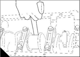
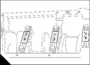
19 Carefully push the pistons into their bores (B). |
|
20 Ensure that the tops of the main bearing caps are stamped with their relevant position number (C). |
|
5 |
|
B |
|
C |
|
W083 |
|
W095 |
|
21 Remove the main bearing caps and the lower shell-bearings. Keep the bearings with their relevant bearing caps. |
|
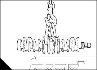
22 Lift out the crankshaft (D). |
|
23 Remove the upper shell-bearings (E) and keep each bearing with its relevant lower shell-bearing and bearing cap. |
|
D |
|
E |
|
W096 |
|
W097/1 |
|
76 |
|
Workshop Manual, TPD 1353E, Issue 3 |
|
This document has been printed from SPI². Not for Resale |
![]()
![]()
|
5 |
|
Peregrine EDi and 1300 Series EDi To fit |
|
Operation 5-8 |
|
Warning! Use lift equipment or obtain assistance to lift heavy engine components such as the flywheel housing, flywheel and crankshaft. |
|
1 Ensure that all lubricating oil passages are clean and free from restriction. 2 Clean the main bearing housings and the upper shell-bearings. 3 Fit the upper shell-bearings (A2) with the location tags (A3) fitted correctly in their recesses. 4 Ensure that the large lubricating oil hole (A1) in the bearing is toward the camshaft side of the engine. 5 Lubricate the bearings with clean engine lubricating oil. |
|
6 Ensure that the main journals of the crankshaft are clean. |
|
7 Put the crankshaft in position on the upper shell-bearings. |
|
8 Clean the bearing caps and the lower shell-bearings. |
|
9 Fit the bearings to the caps with the location tags fitted correctly in their recesses. 10 Lubricate the bearings with clean engine lubricating oil. |
|
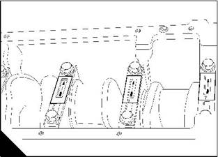
11 Fit the bearing caps numbers 1 to 6 in their correct positions, as shown by the position number stamped on the top of the cap (B). |
|
Caution: Ensure that the arrows (B) stamped on the bearing caps are facing toward the camshaft side of the engine. |
|
3 |
|
1 2 |
|
5 |
|
A |
|
B |
|
W097 |
|
W095 |
|
12 Lightly lubricate the setscrews with clean engine lubricating oil. |
|
13 Fit the setscrews for the main bearing caps numbers 1 to 6, and tighten the setscrews gradually and evenly to the specific torques shown below: |
|
WK, WL, WM, and WN engines - 157 Nm (116 lbf ft) 16,0 kgf m |
|
WK, WL, WM, and WN engines (from engine serial number 850000) - 176 Nm (130 lbf ft) 18,0 kgf m. Caution: For WP, WQ, WR, and WS engines, new setscrews must be fitted whenever bearing caps are fitted. For WP, WQ, WR, and WS engines: |
|
Tighten each main bearing cap setscrew evenly and gradually to 135 Nm (100 lbf ft) 13,8 kgf m. Tighten each main bearing cap setscrew to 177 Nm (130 lbf ft) 18,0 kgf m. Continued |
|
Workshop Manual, TPD 1353E, Issue 3 |
|
77 |
|
This document has been printed from SPI². Not for Resale |
![]()
![]()
![]()
![]()
|
5 |
|
Peregrine EDi and 1300 Series EDi |
|
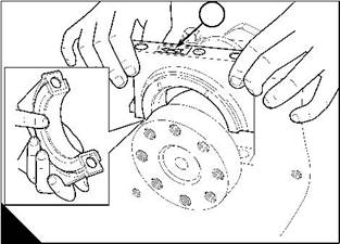
14 Fit the rear main bearing cap, number 7, in position on the rear main journal (C). |
|
Caution: Ensure that the arrow (C1) stamped on the bearing cap is facing toward the camshaft side of the engine. |
|
15 To centre the thrust bearing, move the crankshaft to the front or to the back with a suitable lever. |
|
16 Fit the setscrews to the rear main bearing cap and tighten the setscrews gradually and evenly to the specific torques shown in step 13. |
|
17 Rotate the crankshaft two turns to ensure free movement. 18 Check the crankshaft end-float, see Operation 5-11. |
|
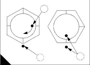
19 For WP, WQ, WR, and WS engines, tighten all the main bearing cap setscrews a further 90°. To do this, apply a mark (D1) to each setscrew head or socket spanner, and another mark (D2) at 90° clockwise on the crankcase surface as shown. Tighten each setscrew until the two marks align (D3). |
|
1 |
|
1 |
|
3 |
|
2 |
|
C |
|
D |
|
W052/1 |
|
W1383 |
|
20 Fit the piston and connecting rod assemblies, see Operation 4-5. 21 Fit the lubricating oil suction pipe and strainer, see Operation 10-11. 22 Fit the rear oil seal housing, see Operation 5-5. 23 Fit the lubricating oil sump, see Operation 10-10. 24 Fit the flywheel housing, see Operation 13-4. 25 Fit the flywheel, see Operation 13-2. |
|
26 Fit the timing case backplate, see Operation 6-6. 27 Fit the timing case idler gears, see Operation 6-4. 28 Fit the timing case cover, see Operation 6-2. 29 Fit the compressor, see Operation 15-1. |
|
30 Fit the high-pressure pump, see Operation 10-22. 31 Fit the alternator and its mounting bracket, see Operation 14-1. 32 Fit the lubricating oil pump, see Operation 10-13. 33 Fit the pulley / damper assembly, see Operation 5-2. 34 Fit the coolant pump, see Operation 12-4. |
|
35 Fit the fan drive pulley and housing, see Operation 12-6. 36 Fit the fan, see Operation 12-5. |
|
37 Fit the fan drive belt, see Operation 12-7. |
|
38 After the engine has been installed in the application, fill the lubricating oil sump to the correct level with an approved oil, see Chapter 5 in the User’s Handbook. |
|
39 Fill the cooling system. |
|
78 |
|
Workshop Manual, TPD 1353E, Issue 3 |
|
This document has been printed from SPI². Not for Resale |
![]()
![]()
|
5 |
|
Peregrine EDi and 1300 Series EDi To inspect |
|
Operation 5-9 |
|
Check the crankshaft for wear and other damage. The maximum permissible wear and ovality on the crankshaft journals is 0,05 mm (0.002 in). The maximum permissible wear and ovality on the crank pins is 0,0075 mm (0.00025 in). |
|
The main journals and the crank pins of standard size crankshafts can be machined to 0,25 mm (0.010 in), 0,50 mm (0.020 in) or 0,75 mm (0.030 in) undersize on diameter. Refer to the relevant Data and dimensions for the "Crankshaft assembly" on page 14. Special undersize bearings are available. |
|
Workshop Manual, TPD 1353E, Issue 3 |
|
79 |
|
This document has been printed from SPI². Not for Resale |
![]()
![]()
![]()
![]()
|
5 |
|
Peregrine EDi and 1300 Series EDi |
|
Crankshaft gear |
|
To renew |
|
Operation 5-10 |
|
Warning! Use suitable gloves to protect the hands from heat. |
|
Caution: If the crankshaft gear is to be renewed, the drive spline for the oil pump has to be renewed also. |
|
1 Remove the crankshaft, see Operation 5-7. |
|
2 Put a suitable support (A3) under the crankshaft nose. |
|
Caution: Do not scratch or damage the crankshaft with the chisel or the hammer. If the crankshaft is scratched or damaged, it will have to be reground or renewed. |
|
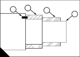
3 Use a hammer and chisel to break the drive spline (A2) for the oil pump, and to break the crankshaft gear (A1). |
|
4 Remove the drive spline for the oil pump, and remove the crankshaft gear. 5 Clean the crankshaft nose. |
|
Caution: Do not fit a cold crankshaft gear, it will be damaged. |
|
6 Heat a new crankshaft gear to 370/395 °F (188/202 °C). |
|
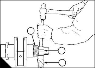
7 Press the crankshaft gear (B2) onto the crankshaft (B4). Ensure that the locating pin (B1) engages in the crankshaft gear. |
|
Caution: Do not fit a cold drive spline, it will be damaged. |
|
8 Heat a new drive spline for the lubricating oil pump to 370/395 °F (188/202 °C). 9 Press the drive spline (B3) onto the crankshaft. |
|
10 Fit the crankshaft, Operation 5-8. |
|
2 |
|
1 |
|
3 |
|
4 |
|
1 |
|
2 |
|
3 |
|
A |
|
B |
|
W053 |
|
W259 |
|
80 |
|
Workshop Manual, TPD 1353E, Issue 3 |
|
This document has been printed from SPI². Not for Resale |
![]()
![]()
![]()
![]()
|
5 |
|
Peregrine EDi and 1300 Series EDi |
|
Thrust bearing |
|
To check crankshaft end-float |
|
Operation 5-11 |
|
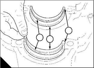
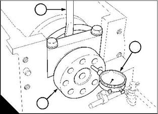
Note: The axial movement of the crankshaft is controlled by a thrust bearing (A1) in the rear (number 7) main bearing cap. The end-float can be checked with a dial test indicator on one end of the crankshaft. |
|
1 Put a dial test indicator (B2) against the face of the crankshaft flange (B3). |
|
2 Use a lever (B1) to move the crankshaft fully toward the front of the engine and set the indicator to zero. 3 Use a lever to move the crankshaft fully toward the rear of the engine and note the indicator reading. |
|
4 Renew the thrust bearing if the end-float is more than the tolerance given in the relevant Data and dimensions for the "Crankshaft assembly" on page 14. |
|
1 |
|
1 |
|
2 |
|
3 |
|
A |
|
B |
|
W052/2 |
|
W030 |
|
Workshop Manual, TPD 1353E, Issue 3 |
|
81 |
|
This document has been printed from SPI². Not for Resale |
![]()
![]()
![]()
![]()
|
5 |
|
Peregrine EDi and 1300 Series EDi |
|
To remove |
|
Operation 5-12 |
|
1 Drain the lubricating oil and the coolant. |
|
2 Remove the lubricating oil sump, see Operation 10-9. |
|
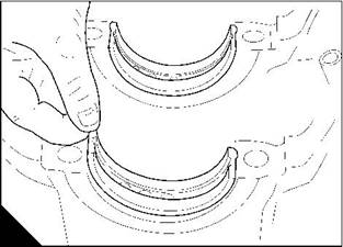
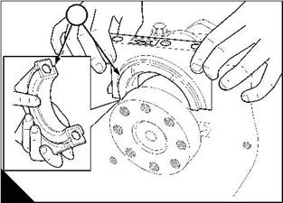
3 Release the setscrews of the rear main bearing and remove the main bearing cap (A) complete with the lower half of the thrust bearing (A1). |
|
4 Push one end of the upper half of the thrust bearing with a suitable tool made of a soft material to slide the bearing out. Where necessary, move the crankshaft to the front or to the rear to loosen a tight bearing. |
|
1 |
|
A |
|
W052/2 |
|
82 |
|
Workshop Manual, TPD 1353E, Issue 3 |
|
This document has been printed from SPI². Not for Resale |
![]()
![]()
![]()
![]()
|
5 |
|
Peregrine EDi and 1300 Series EDi |
|
To fit |
|
Operation 5-13 |
|
1 Lubricate the thrust bearing with clean engine lubricating oil. |
|
2 Slide the upper-half of the thrust bearing into position with the location tag fitted correctly in its recess. Ensure that the large lubricating oil hole in the bearing is toward the camshaft side of the engine. |
|
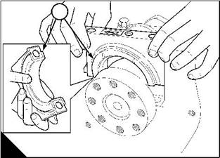
3 Fit the lower-half of the thrust bearing (A1) to the main bearing cap (A3) with the location tag (A4) in its recess. Ensure that the bearing is fitted correctly in the cap and that the bearing and the crankshaft journal are clean. Lubricate the bearing with clean engine lubricating oil. |
|
4 Put the bearing cap in position. Ensure that the arrow (A2) stamped on the bearing cap is toward the camshaft side of the engine. |
|
5 Lightly lubricate the setscrews with clean engine lubricating oil. |
|
6 Fit the setscrews to the main bearing cap, and tighten the setscrews gradually and evenly to the specific torques shown below: |
|
WK, WL, WM, and WN engines - 157 Nm (116 lbf ft) 16,0 kgf m |
|
WK, WL, WM, and WN engines (from engine serial number 850000) - 176 Nm (130 lbf ft) 18,0 kgf m Caution: For WP, WQ, WR, and WS engines, new setscrews must be fitted whenever bearing caps are fitted. WP, WQ, WR, and WS engines: |
|
Tighten each main bearing cap setscrew evenly and gradually to 135 Nm (100 lbf ft) 13,8 kgf m. Tighten each main bearing cap setscrew to 177 Nm (130 lbf ft) 18,0 kgf m. |
|
7 Rotate the crankshaft two turns to ensure free movement. 8 Check the crankshaft end-float, see Operation 5-11. |
|
9 Tighten all the main bearing cap setscrews a further 90°. To do this, apply a mark (B1) to each setscrew head or socket spanner, and another mark (B2) at 90° clockwise on the crankcase surface as shown. Tighten each setscrew until the two marks align (B3). |
|
10 Fit the lubricating oil sump, see Operation 10-10. |
|
11 After the engine has been installed in the application, fill the lubricating oil sump to the correct level with an approved oil, see Chapter 5 in the User’s Handbook. |
|
12 Fill the cooling system. |
|
2 |
|
1 |
|
3 |
|
1 |
|
3 |
|
2 |
|
A |
|
4 |
|
B |
|
W052/3 |
|
W1383 |
|
Workshop Manual, TPD 1353E, Issue 3 |
|
83 |
|
This document has been printed from SPI². Not for Resale |