 English
 Espaol
 Franais
 阿拉伯
阿拉伯 中文
中文 Deutsch
 Italiano
 Português
 日本
日本 韩国
韩国 български
 hrvatski
 esky
esky Dansk
Dansk Nederlands
 suomi
suomi Ελληνικ
 印度
印度 norsk
norsk Polski
 Roman
Roman русский
 Svenska
Perkins珀金斯1306-E87TA86柴油发动机1830593 C94摇臂轴供应商,Perkins珀金斯1306-E87TA86柴油发动机1830593 C94摇臂轴技术价格规格咨询服务,Perkins珀金斯1306-E87TA86柴油发动机1830593 C94摇臂轴零配件供应,Perkins珀金斯1306-E87TA86柴油发动机1830593 C94摇臂轴售后服务中心,Perkins珀金斯1306-E87TA86柴油发动机1830593 C94摇臂轴,Perkins珀金斯1306-E87TA86柴油发动机1830593 C94摇臂轴详细的技术参数,

产品中心
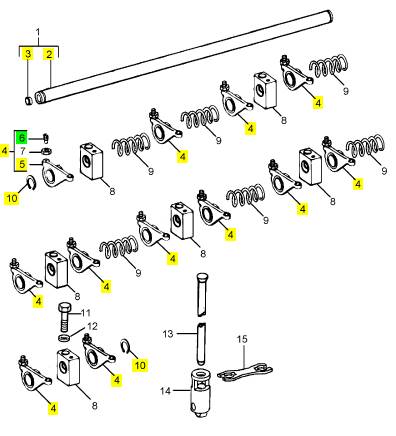
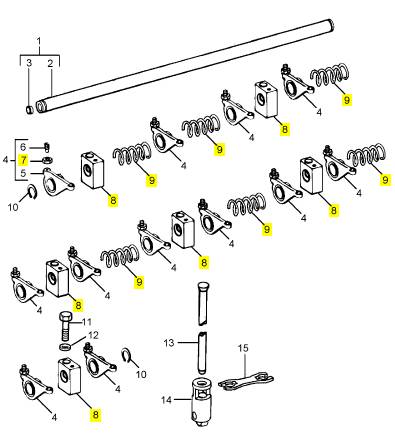
Perkins珀金斯1306-E87TA86柴油发动机1830593 C94摇臂轴
详细描述
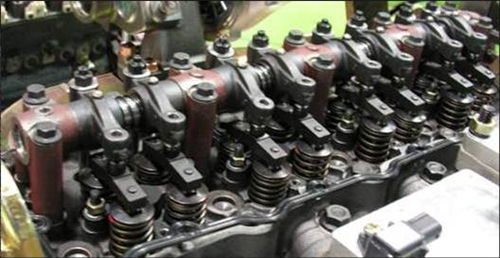
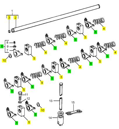
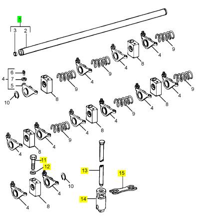
项目 零配件号码 新件号 描述
1 1830593 C94 1 1830593 C94 摇臂轴组合
1 454319 R1 2 454319 R1 CIRCLIP
1 1827195 C93 12 1827195 C95 摇臂杆
1 1827316 C1 5 1827316 C1 摇臂轴弹簧
1 1827435 C1 6 1827435 C1 支撑托架
1 1830592 C91 1 1830592 C91 摇臂轴 ASSY
1 1830593 C92 1 1830593 C94 摇臂轴组合
1 1830593 C93 1 1830593 C94 摇臂轴组合
11 1824955 C2 6 1824955 C2 汽缸盖螺拴
11 1824955 C1 6 1824955 C2 螺拴
12 1814757 C2 6 1814757 C2 垫圈
13 1850010 C1 12 1850010 C1 PUSHROD 1460271
13 1821962 C2 12 1821962 C2 PUSHROD 1460270
14 1809570 C1 12 1809570 C5 挺杆
15 1813892 C1 6 1813892 C1 导入
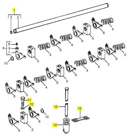
项目 零配件号码 新件号 描述
2 1 摇臂轴
3 327412 R1 2 40005 R1 栓塞
4 1827316 C1 5 1827316 C1 摇臂轴弹簧
5 1827435 C1 5 1827435 C1 支撑托架
6 1827195 C95 12 1827195 C95 摇臂杆
10 454319 R1 2 454319 R1 CIRCLIP
项目 零配件号码 新件号 描述
1 1872757 C91 1 1872757 C91 摇臂轴组合
11 1824955 C2 6 1824955 C2 汽缸盖螺拴
12 1814757 C2 6 1814757 C2 垫圈
13 1872746 C2 12 1872746 C2 PUSHROD
14 1850160 C3 12 1850160 C3 挺杆
15 1813892 C1 12 1813892 C1 导入
项目 零配件号码 新件号 描述
2 1 摇臂轴
3 327412 R1 2 40005 R1 栓塞
4 1827316 C1 5 1827316 C1 摇臂轴弹簧
5 1827435 C1 5 1827435 C1 支撑托架
6 1872755 C91 12 1872755 C91 摇臂杆
10 454319 R1 2 454319 R1 CIRCLIP
项目 零配件号码 新件号 描述
7 1 摇臂
8 1854757 C1 1 1854757 C1 螺旋
9 1841734 C1 1 1841734 C1 螺帽
|
Main bearings |
|
To remove |
|
Operation 5-14 |
|
1 Drain the lubricating oil and remove the sump, see Operation 10-9. 2 Remove all necessary components to get access to the specific bearing cap. 3 Release the setscrews of the bearing cap and remove the bearing cap (A). 4 Remove the lower shell-bearing from the cap. |
|
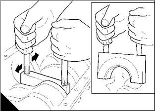
5 With a suitable tool, push the upper shell-bearing from the side opposite to the location tag to remove the bearing tag from its recess in the bearing housing. |
|
6 Carefully rotate the crankshaft counter-clockwise (viewed from the rear of the engine) to release the bearing from its housing. |
|
7 Keep the halves of the shell-bearing in their relevant positions. |
|
A |
|
W139 |
|
84 |
|
Workshop Manual, TPD 1353E, Issue 3 |
|
This document has been printed from SPI². Not for Resale |
![]()
![]()
![]()
![]()
|
5 |
|
Peregrine EDi and 1300 Series EDi To fit |
|
Operation 5-15 |
|
1 Clean the upper shell-bearing and lubricate the bearing surface with clean engine lubricating oil. |
|
2 Fit the plain end of the upper shell-bearing between the crankshaft journal and the side of the bearing housing which has the recess for the location tag. Slide the bearing into its housing until the tag on the bearing is fitted correctly in its recess in the housing. |
|
3 Clean the lower shell-bearing and the cap, lubricate the bearing surface with clean engine lubricating oil. 4 Fit the bearing into the cap with the tag of the bearing fitted correctly in the recess in the cap. 5 Fit the bearing cap with the location tags of both shell-bearings on the same side. 6 Lightly lubricate the setscrews with clean engine lubricating oil. |
|
7 Fit the setscrews for the main bearing caps numbers 1 to 6, and tighten the setscrews gradually and evenly to the specific torques shown below: |
|
WK, WL, WM, and WN engines - 157 Nm (116 lbf ft) 16,0 kgf m |
|
WK, WL, WM, and WN engines (from engine serial number 850000) - 176 Nm (130 lbf ft) 18,0 kgf m. Caution: For WP, WQ, WR, and WS engines, new setscrews must be fitted whenever bearing caps are fitted. For WP, WQ, WR, and WS engines: |
|
Tighten each main bearing cap setscrew evenly and gradually to 135 Nm (100 lbf ft) 13,8 kgf m. Tighten each main bearing cap setscrew to 177 Nm (130 lbf ft) 18,0 kgf m. |
|
8 Ensure that the crankshaft rotates freely. If the thrust bearing (number 7) has been removed and fitted, check the crankshaft end-float, see Operation 5-11. |
|
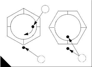
9 For WP, WQ, WR, and WS engines, tighten all the main bearing cap setscrews a further 90°. To do this, apply a mark (A1) to each setscrew head or socket spanner, and another mark (A2) at 90° clockwise on the crankcase surface as shown. Tighten each setscrew until the two marks align (A3). |
|
10 Fit all the components that were removed for access to the main bearing caps. 11 Fit the lubricating oil sump, see Operation 10-10. |
|
12 Fill the lubricating oil sump to the correct level with an approved lubricating oil, see Chapter 5 in the User’s Handbook. |
|
1 |
|
3 |
|
2 |
|
A |
|
W1383 |
|
Workshop Manual, TPD 1353E, Issue 3 |
|
85 |
|
This document has been printed from SPI². Not for Resale |
![]()
![]()
![]()
![]()
|
5 |
|
Peregrine EDi and 1300 Series EDi |
|
To inspect |
|
Operation 5-16 |
|
Inspect the bearings for wear and for other damage. If a bearing is worn or damaged, renew both shell- bearings and check the condition of the other bearings. |
|
If the thrust bearing (number 7) has been removed and fitted, check the crankshaft end-float, see Operation 5-11. |
|
86 |
|
Workshop Manual, TPD 1353E, Issue 3 |
|
This document has been printed from SPI². Not for Resale |
![]()
![]()
![]()
![]()
|
Peregrine EDi and 1300 Series EDi |
|
6 |
|
Timing case and drive assembly |
|
6 |
|
General description |
|
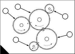
The aluminium timing case, which is a two piece casting, contains the drive gears. There are two idler gears: the lower idler gear (A4) and the upper idler gear (A2). The lower idler gear is driven by the crankshaft gear (A5) and drives the upper idler gear and, if fitted, the compressor. The upper idler gear drives the camshaft gear (A1) and the gear (A3) for the high-pressure pump. All of the gears have timing marks except the gear for the high-pressure pump. There is a spline on the crankshaft nose to drive the lubricating oil pump. A power take-off can be fitted to the right hand side of the engine. If one is fitted, it is driven by the lower idler gear. |
|
The idler gears are mounted on taper roller bearings. The camshaft gear rotates at half engine speed. |
|
The timing case assembly has channels and ports for the coolant and for the lubricating oil. This reduces the need for external pipes and improves engine reliability. |
|
The camshaft rotates in four bushes that can be renewed. |
|
2 |
|
1 |
|
3 |
|
4 |
|
5 |
|
A |
|
W032/2 |
|
Workshop Manual, TPD 1353E, Issue 3 |
|
87 |
|
This document has been printed from SPI². Not for Resale |
![]()
![]()

|
6 |
|
Peregrine EDi and 1300 Series EDi |
|
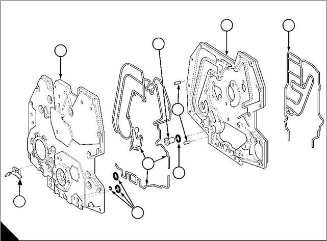
Components of the timing case |
|
1 Timing case cover 2 Pressure relief valve 3 Dowels |
|
4 Timing case backplate 5 Joint |
|
6 ‘O’ ring |
|
7 Joints |
|
8 ‘O’ rings |
|
9 Timing indicator |
|
4 |
|
5 |
|
2 |
|
1 |
|
3 |
|
7 |
|
6 |
|
9 |
|
8 |
|
A |
|
W231 |
|
88 |
|
Workshop Manual, TPD 1353E, Issue 3 |
|
This document has been printed from SPI². Not for Resale |
![]()
![]()
|
6 |
|
Peregrine EDi and 1300 Series EDi |
|
Timing case cover |
|
To remove |
|
Operation 6-1 |
|
1 Drain the engine lubricating oil. |
|
2 Drain the cooling system. |
|
3 Remove the fan drive belt, see Operation 12-7. |
|
4 Remove the fan, see Operation 12-5. |
|
5 Remove the fan drive pulley and fan mounting, see Operation 12-6. 6 Remove the fan drive belt tensioner. |
|
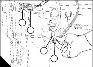
7 Disconnect and remove the camshaft motion sensor (CMS), see Operation 6-11. 8 Remove the alternator and its mounting bracket, see Operation 14-1. 9 Remove the pulley/damper assembly, see Operation 5-1. 10 Remove the coolant pump pulley and the coolant pump, see Operation 12-4. 11 Disconnect the electrical cable (A2) at the sensor (A1) for engine oil temperature. |
|
12 Disconnect the electrical cable (A4) at the solenoid (A3) of the regulator valve for injection control pressure. 13 Remove the sensor (A1). |
|
14 Use a suitable pump to drain the reservoir for the high-pressure system. Drain the reservoir through the hole for the sensor. |
|
15 Remove the lubricating oil pump, see Operation 10-12. |
|
16 Release the nuts, bolts and setscrews of the timing case cover and remove the timing case cover. 17 Remove and discard the ’O’ rings (page 88/A8) and joints (page 88/A7). |
|
1 |
|
2 |
|
3 |
|
4 |
|
A |
|
W229 |
|
Workshop Manual, TPD 1353E, Issue 3 |
|
89 |
|
This document has been printed from SPI². Not for Resale |
![]()
![]()
![]()
![]()
|
6 |
|
Peregrine EDi and 1300 Series EDi |
|
To fit |
|
Operation 6-2 |
|
1 Clean the faces of the timing case cover. |
|
2 Put new joints and ’O’ rings on the cover and put the cover in position on its dowels (page 88/A3). The dowels are at the 1 o’clock and the 7 o’clock positions. |
|
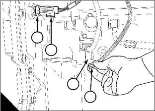
3 Loosely fit two opposite setscrews to hold the cover in place. 4 Fit the remainder of the fasteners and tighten all the cover fasteners to 22 Nm (16 lbf ft) 2,2 kgf m. 5 Fit the sensor (A1) for engine oil temperature and connect its electrical cable (A2). 6 Connect the electrical cable (A4) to the injection control pressure regulator (A3). 7 Fit the coolant pump and the coolant pump pulley, see Operation 12-4. 8 Fit the lubricating oil pump, see Operation 10-13. |
|
9 Fit the pulley / damper assembly, see Operation 5-2. |
|
10 Fit the alternator mounting bracket and the alternator, see Operation 14-1. 11 Fit the fan drive belt tensioner. |
|
12 Verify the CMS air gap, see Operation 6-12. |
|
13 Fit the CMS sensor, see Operation 6-11. |
|
14 Fit the fan mounting and drive pulley, see Operation 12-6. 15 Fit the fan, see Operation 12-5. |
|
16 Fit the fan drive belt, see Operation 12-7. |
|
17 Fill the lubricating oil sump to the correct level with an approved lubricating oil, see Chapter 5 in the User’s Handbook. |
|
18 Fill the cooling system to the correct level. |
|
1 |
|
2 |
|
3 |
|
4 |
|
A |
|
W229 |
|
90 |
|
Workshop Manual, TPD 1353E, Issue 3 |
|
This document has been printed from SPI². Not for Resale |
![]()
![]()
![]()
![]()
|
6 |
|
Peregrine EDi and 1300 Series EDi |
|
Idler gears |
|
To remove |
|
Operation 6-3 |
|
Cautions: |
|
l The setscrew for the upper idler gear (C1) enters the water jacket. To prevent leakage of coolant, the setscrew is supplied with a sealant on its thread. |
|
l The setscrew for the upper idler gear must be renewed when it is removed from the engine. 1 Set number 1 cylinder to TDC on the compression stroke, see Operation 8-1. 2 Drain the cooling system. |
|
3 Remove the timing case cover, see Operation 6-1. |
|
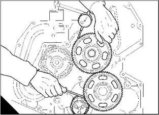
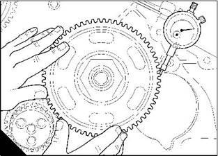
4 Measure and record the backlash of the upper idler gear (A). Measure and record the backlash of the lower idler gear (B). Compare the results with the relevant Data and dimensions for the "Timing gears" on page 15. Renew any gear that is out of tolerance. |
|
A |
|
B |
|
W233/1 |
|
W234/1 |
|
5 Remove and discard the setscrew of the upper idler gear. Remove the upper idler gear. 6 Remove the setscrew of the lower idler gear and remove the lower idler gear (C2). |
|
Caution: If the crankshaft is rotated with either of the idler gears removed, the timing of the engine will be incorrect. |
|
7 Inspect the gears and their bearings for wear and other damage and renew them as necessary. The gears and their taper roller bearings must be renewed as an assembly. |
|
1 |
|
2 |
|
C |
|
W032/4 |
|
Workshop Manual, TPD 1353E, Issue 3 |
|
91 |
|
This document has been printed from SPI². Not for Resale |
![]()
![]()
![]()
![]()
![]()
|
6 |
|
Peregrine EDi and 1300 Series EDi |
|
To fit |
|
Operation 6-4 |
|
Caution: Ensure that the piston of number 1 cylinder is set to TDC. |
|
1 Lubricate the bearings of the idler gears with clean engine lubricating oil. |
|
2 Lightly lubricate the threads and shoulder of the setscrew for the lower idler gear with clean engine lubricating oil. |
|
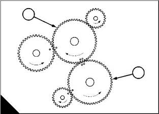
3 Put the lower idler gear (A4) in position and in mesh with the crankshaft gear (A5) so that the timing marks align (A). |
|
4 Fit and tighten the setscrew to 637 Nm (470 lbf ft) 65,6 kgf m. |
|
5 Ensure that the thread in the cylinder block for the setscrew of the upper idler gear is clean and dry. |
|
6 The new setscrew for the upper idler gear (A2) is supplied with a sealant on its thread. Do not add more sealant to the thread of the setscrew. Do not apply lubricating oil to the thread of this setscrew. |
|
7 Put the upper idler gear in position and in mesh with the camshaft gear (A1), the lower idler gear and the high-pressure pump gear (A3). Ensure that the timing marks (A) align on the upper idler gear, the camshaft gear, the crankshaft gear and the lower idler gear. |
|
Note: There are no timing marks on the high-pressure pump gear. |
|
8 Fit and tighten the new setscrew for the upper idler gear to 332 Nm (245 lbf ft) 33,8 kgf m. 9 Check that the backlash of the gears is still within tolerance. Renew any gear that is out of tolerance. 10 Fit the timing case cover, see Operation 6-2. |
|
11 Fill the cooling system to the correct level. |
|
2 |
|
1 |
|
3 |
|
4 |
|
5 |
|
A |
|
W032/2 |
|
92 |
|
Workshop Manual, TPD 1353E, Issue 3 |
|
This document has been printed from SPI². Not for Resale |
![]()
![]()
![]()
![]()
|
6 |
|
Peregrine EDi and 1300 Series EDi |
|
Timing case backplate |
|
To remove |
|
Operation 6-5 |
|
1 Remove the timing case cover, see Operation 6-1. 2 Remove the high-pressure pump, see Operation 10-21. |
|
3 Remove the power steering pump, see Operation 15-2, the compressor, see Operation 15-1, and their mounting brackets, if these auxiliaries are fitted. |
|
4 Remove and discard the coolant filter. |
|
5 Remove the idler gears, see Operation 6-3. |
|
6 Remove the oil pressure relief valve (A2) from the crankcase. 7 Remove the rocker assembly, see Operation 3-4. Remove all the push rods and note their relative positions. 8 Remove the cylinder head, see Operation 3-8. |
|
9 Remove the tappets from their bores and note their relative positions. 10 Remove the camshaft, see Operation 6-7. |
|
11 Remove the setscrews and remove the timing case backplate. The backplate is located on two dowels (A3). |
|
12 Remove the timing case backplate (A4). |
|
4 |
|
5 |
|
2 |
|
1 |
|
3 |
|
7 |
|
6 |
|
9 |
|
8 |
|
A |
|
W231 |
|
Workshop Manual, TPD 1353E, Issue 3 |
|
93 |
|
This document has been printed from SPI². Not for Resale |