 English
 Espaol
 Franais
 阿拉伯
阿拉伯 中文
中文 Deutsch
 Italiano
 Português
 日本
日本 韩国
韩国 български
 hrvatski
 esky
esky Dansk
Dansk Nederlands
 suomi
suomi Ελληνικ
 印度
印度 norsk
norsk Polski
 Roman
Roman русский
 Svenska
Perkins珀金斯1306-E87TA86柴油发动机1833357 C95机油泵供应商,Perkins珀金斯1306-E87TA86柴油发动机1833357 C95机油泵技术价格规格咨询服务,Perkins珀金斯1306-E87TA86柴油发动机1833357 C95机油泵零配件供应,Perkins珀金斯1306-E87TA86柴油发动机1833357 C95机油泵售后服务中心,Perkins珀金斯1306-E87TA86柴油发动机1833357 C95机油泵,Perkins珀金斯1306-E87TA86柴油发动机1833357 C95机油泵详细的技术参数,

产品中心
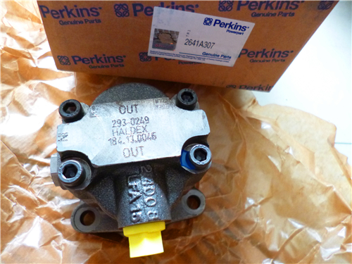
Perkins珀金斯1306-E87TA86柴油发动机1833357 C95机油泵
详细描述
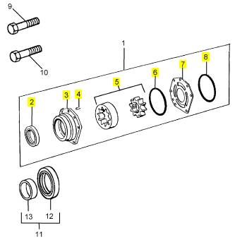
项目 零配件号码 新件号 描述
1 1833357 C91 1 1833357 C95 油泵
9 1817859 C1 4 1817859 C1 公制的螺拴
10 1817957 C1 2 1817957 C1 公制的螺拴
11 1833096 C92 1 1833096 C94 密封 -前油封
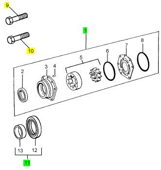
项目 零配件号码 新件号 描述
2 1 油密封
3 1 油泵壳
4 680482 C1 2 680482 C1 合钉
5 1 转子
6 1817862 C1 1 1817862 C1 密封O型圈
7 1827400 C1 1 1827400 C1 架设板
8 1817862 C1 1 1817862 C1 密封O型圈
|
o fit |
|
Operation 6-6 |
|
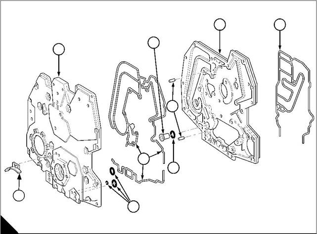
1 Clean and inspect all components for wear or damage. Inspect the timing case for cracks, especially around the channels for the engine fluids. |
|
2 Fit a new joint (A5) to the backplate. |
|
3 Engage the backplate dowels (A3) and push the backplate onto the engine. |
|
4 Lightly lubricate the threads and shoulders of the setscrews for the backplate with clean engine lubricating oil. |
|
5 Fit and tighten the setscrews to 26 Nm (19 lbf ft) 2,6 kgf m. 6 Fit the camshaft, see Operation 6-8. |
|
7 Fit the tappets into their original bores. 8 Fit the cylinder head, see Operation 3-9. 9 Fit the oil pressure relief valve together with its ‘O’ ring (A6). 10 Fit the idler gears, see Operation 6-4. 11 Fit a new coolant filter. |
|
12 Fit the power steering pump, see Operation 15-2, the compressor, see Operation 15-1, and their mounting brackets, if removed earlier. |
|
13 Fit the high-pressure pump, see Operation 10-22. |
|
14 Fit the timing case cover, see Operation 6-2. |
|
15 Fill the cooling system to the correct level. |
|
16 Fill the lubricating system to the correct level with an approved oil, see Chapter 5 in the User’s Handbook. |
|
4 |
|
5 |
|
2 |
|
1 |
|
3 |
|
7 |
|
6 |
|
9 |
|
8 |
|
A |
|
W231 |
|
94 |
|
Workshop Manual, TPD 1353E, Issue 3 |
|
This document has been printed from SPI². Not for Resale |
![]()
![]()
![]()
![]()
|
6 |
|
Peregrine EDi and 1300 Series EDi |
|
Camshaft and tappets |
|
To remove |
|
Operation 6-7 |
|
Caution: The camshaft gear is an interference fit on the camshaft and must not be removed unless it is to be renewed. A new gear must be heated to 206 °C (400 °F) to fit onto the camshaft. |
|
Notes: |
|
l The four camshaft bushes can be renewed. l An engine timing plate is fitted to the camshaft gear. 1 Set number 1 cylinder to TDC on the compression stroke, see Operation 8-1. 2 Drain the engine lubricating oil. |
|
3 Drain the cooling system. |
|
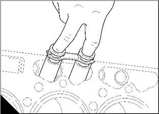
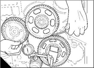
4 Remove the timing case cover, see Operation 6-1. 5 Remove the cylinder head, see Operation 3-8. 6 Remove the tappets (A) from their bores and note their relative positions. |
|
7 Measure the backlash of the camshaft gear (B) and compare the reading with relevant Data and dimensions for the "Timing gears" on page 15. If the backlash is incorrect, renew the gear. |
|
A |
|
B |
|
W038 |
|
W235 |
|
Continued |
|
Workshop Manual, TPD 1353E, Issue 3 |
|
95 |
|
This document has been printed from SPI². Not for Resale |
![]()
![]()
![]()
![]()
![]()

|
6 |
|
Peregrine EDi and 1300 Series EDi |
|
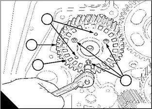
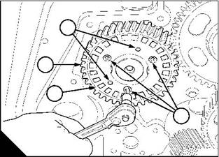
8 Remove the cap screws (C2) that retain the timing plate (C3). |
|
9 Remove the timing plate from its dowels (C1). |
|
10 Remove the setscrews from the camshaft thrust plate, access to the setscrews is through the two holes in the gear face (D). |
|
11 Carefully remove the camshaft complete with the gear. |
|
1 |
|
4 |
|
3 |
|
2 |
|
C |
|
D |
|
W237 |
|
W236 |
|
96 |
|
Workshop Manual, TPD 1353E, Issue 3 |
|
This document has been printed from SPI². Not for Resale |
![]()
![]()
|
6 |
|
Peregrine EDi and 1300 Series EDi |
|
To fit |
|
Operation 6-8 |
|
1 Ensure that all components are clean and are lubricated with clean engine lubricating oil. |
|
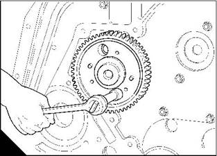
2 Carefully fit the camshaft. Ensure that the timing marks on the upper idler gear and the camshaft gear align. If a new gear is fitted, measure the backlash (A). |
|
3 Engage the timing plate dowels (B1) and push the timing plate (B3) onto the camshaft gear (B4), fit and tighten the cap screws (B2) to 7 Nm (5 lbf ft) 0,7 kgf m. |
|
1 |
|
4 |
|
3 |
|
2 |
|
A |
|
B |
|
W235 |
|
W237 |
|
4 Fit the tappets (C) into their original bores. 5 Fit the cylinder head, see Operation 3-9. 6 Fit the timing case cover, see Operation 6-2. 7 Fill the cooling system to the correct level. |
|
8 Fill the lubricating oil sump to the correct level with an approved lubricating oil, see Chapter 5 in the User’s Handbook. |
|
C |
|
W038 |
|
Workshop Manual, TPD 1353E, Issue 3 |
|
97 |
|
This document has been printed from SPI². Not for Resale |
![]()
![]()
![]()
![]()

|
6 |
|
Peregrine EDi and 1300 Series EDi |
|
To inspect |
|
Operation 6-9 |
|
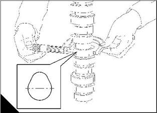
With the camshaft removed from the engine, measure the camshaft lobes at line AA and at line BB in figure (A) and record the readings. |
|
Measure the tappets, the thrust plate and the camshaft bushes. Compare all the readings with the relevant Data and dimensions for the "Camshaft" on page 15. Renew damaged or worn components as necessary. |
|
A |
|
B |
|
B |
|
A |
|
A |
|
W042 |
|
98 |
|
Workshop Manual, TPD 1353E, Issue 3 |
|
This document has been printed from SPI². Not for Resale |
![]()
![]()
![]()
![]()
|
6 |
|
Peregrine EDi and 1300 Series EDi |
|
Camshaft bushes |
|
To renew |
|
Operation 6-10 |
|
Special requirements Special tools |
|
Description |
|
Part number |
|
Camshaft bush remover and replacer |
|
21825963 |
|
The four camshaft bushes have the same internal diameter, but the external diameters are different for each bush. Refer to the relevant Data and dimensions for the "Camshaft bushes" on page 15. |
|
The bushes must be removed and fitted in the correct sequence, they shall be referred to in this manual as number 1 bush, number 2 bush, number 3 bush and number 4 bush. Number 1 bush is at the front of the engine. |
|
The rear bush is removed toward the rear of the engine, the other three bushes are removed toward the front of the engine. |
|
1 Remove the camshaft, see Operation 6-7. |
|
Note: Use Tool 21825995 to remove and to fit the bushes. |
|
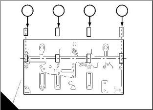
2 To remove number 4 bush (A4), pull it toward the rear of the engine. |
|
3 To remove the other three bushes, pull them toward the front of the engine in the sequence: number 1 bush (A1), number 2 bush (A2) then the number 3 bush (A3). |
|
4 Clean and inspect the bush housings for damage. Ensure that all the lubricating oil holes are free of debris. 5 Lubricate the bushes and the bush housings with clean engine lubricating oil. |
|
Caution: Ensure that the lubricating oil holes of each bush are on the same side, and aligned with the lubricating oil holes in the crankcase. |
|
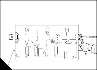
6 Fit number 4 bush (B); put it into position from the rear of the engine and then pull it toward the front of the engine. |
|
4 |
|
3 |
|
2 |
|
1 |
|
A |
|
B |
|
W041 |
|
W044 |
|
Continued |
|
Workshop Manual, TPD 1353E, Issue 3 |
|
99 |
|
This document has been printed from SPI². Not for Resale |
![]()
![]()
![]()
![]()

|
6 |
|
Peregrine EDi and 1300 Series EDi |
|
7 Fit the other three bushes (C) in the sequence: number 3 bush, number 2 bush then the number 1 bush. Put each bush into position from the front of the engine and then pull it toward the rear of the engine. |
|
8 Fit the camshaft, see Operation 6-8. |
|
C |
|
W043 |
|
100 |
|
Workshop Manual, TPD 1353E, Issue 3 |
|
This document has been printed from SPI². Not for Resale |
![]()
![]()
|
6 |
|
Peregrine EDi and 1300 Series EDi |
|
Camshaft motion sensor (CMS) |
|
To remove and to fit |
|
Operation 6-11 |
|
To remove |
|
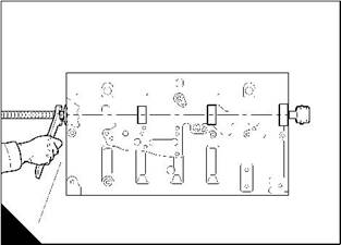
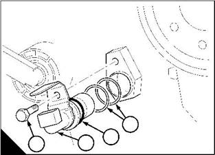
1 Disconnect the main wiring harness connector from the camshaft motion sensor (A2). 2 Remove the sensor setscrew (A1). Rotate and pull the sensor from the timing cover. 3 Retain the shims (A4) for when the sensor is fitted. |
|
To fit |
|
1 Clean the surfaces, and apply a small amount of engine lubricating oil to the ‘O’ ring (A3) on the CMS sensor. 2 Fit the same shims (A4) to the sensor (A2). |
|
3 Rotate and push the sensor into the timing cover. |
|
4 Align the sensor and tighten the setscrew (A1). |
|
5 Connect the wiring harness to the sensor. |
|
4 |
|
3 2 |
|
A |
|
1 |
|
W1393 |
|
Workshop Manual, TPD 1353E, Issue 3 |
|
101 |
|
This document has been printed from SPI². Not for Resale |
![]()
![]()
![]()
![]()
|
6 |
|
Peregrine EDi and 1300 Series EDi |
|
CMS verification of clearance |
|
To check the air gap |
|
1 Remove the CMS sensor, see Operation 6-11. |
|
2 Clean the CMS mounting surface on the timing cover. |
|
3 Using a calibrated depth gauge device, measure the distance from the CMS mounting surface to a tooth on the timing disc and note the reading. |
|
Note: When taking this measurement, ensure that the depth gauge device is measuring to a tooth of the timing disc and not the window between the teeth, this applies also to steps 4, 5, and 6. |
|
1 |
|
4 Rotate the crankshaft / turn clockwise and repeat step 3, note the reading. |
|
2 |
|
1 |
|
5 Rotate the crankshaft a further / turn clockwise and repeat step 3, note the reading. |
|
2 |
|
1 |
|
6 Rotate the crankshaft a further / turn clockwise and repeat step 3, note the reading. |
|
2 |
|
7 Add the measurements from steps 3, 4, 5, and 6. |
|
8 Divide the total by 4 to obtain an average reading. |
|
9 Measure the CMS sensor length from its tip to the mounting flange surface. 10 Subtract the dimension at step 9 from the average dimension at step 8. This is the CMS ‘air gap’. 11 The desired air gap is given in the relevant Data and dimensions for the "Camshaft" on page 15. 12 Subtract step 11 from the result of step 10, this is the air gap / interference. |
|
Note: Extra shims are available in a kit that contains four shims, two of 0,127 mm (0.005 in) thickness, and two of 0,254 mm (0.010 in) thickness. |
|
13 Select one or more shims to get as near as possible to the air gap measurement in step 11. 14 Fit the shims to the ‘CMS’ sensor and then fit the sensor, see Operation 6-11. |
|
102 |
|
Workshop Manual, TPD 1353E, Issue 3 |
|
This document has been printed from SPI². Not for Resale |
![]()
![]()
![]()
![]()
|
Peregrine EDi and 1300 Series EDi |
|
7 |
|
Cylinder block assembly |
|
7 |
|
General description |
|
The cylinder block is made of cast iron and provides support for the wet cylinder liners, which are also made of cast iron. |
|
Four bushes are fitted to the cylinder block for the camshaft journals. |
|
Workshop Manual, TPD 1353E, Issue 3 |
|
103 |
|
This document has been printed from SPI². Not for Resale |