 English
 Espaol
 Franais
 阿拉伯
阿拉伯 中文
中文 Deutsch
 Italiano
 Português
 日本
日本 韩国
韩国 български
 hrvatski
 esky
esky Dansk
Dansk Nederlands
 suomi
suomi Ελληνικ
 印度
印度 norsk
norsk Polski
 Roman
Roman русский
 Svenska
Perkins珀金斯1306-E87TA86柴油发动机1841741 C92机油冷油器供应商,Perkins珀金斯1306-E87TA86柴油发动机1841741 C92机油冷油器技术价格规格咨询服务,Perkins珀金斯1306-E87TA86柴油发动机1841741 C92机油冷油器零配件供应,Perkins珀金斯1306-E87TA86柴油发动机1841741 C92机油冷油器售后服务中心,Perkins珀金斯1306-E87TA86柴油发动机1841741 C92机油冷油器,Perkins珀金斯1306-E87TA86柴油发动机1841741 C92机油冷油器详细的技术参数,

产品中心
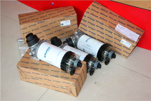
Perkins珀金斯1306-E87TA86柴油发动机1841741 C92机油冷油器
详细描述
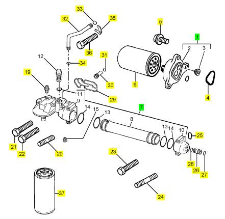
项目 零配件号码 新件号 描述
1 1 过滤器座
4 1 O 圈
5 3 公制的螺拴
6 1 水过滤器
7 1841741 C92 1 1841741 C92 机油冷油器
7 1830622 C91 1 1841741 C92 机油冷油器
7 1830622 C92 1 1841741 C92 机油冷油器
7 1830622 C92 1 1841741 C92 机油冷油器
7 1841739 C91 1 1841741 C92 机油冷油器
19 606819 C1 1 606819 C1 连接
20 1819931 C1 1 1819931 C1 图钉
21 1817958 C1 1 1817958 C1 螺旋
22 1817962 C1 3 1817962 C1 螺拴
23 1817962 C1 1 1817962 C1 螺拴
24 1819931 C1 1 1819931 C1 图钉
25 1830362 C1 1 1830362 C1 密封
26 1830190 C1 1 1830190 C1 管
27 1821098 C2 1 1821098 C2 密封O型圈
28 1821098 C2 1 1821098 C2 密封O型圈
29 1817849 C3 1 1817849 C3 密封垫片 - 滤油器的座
29 1817849 C2 1 1817849 C3 密封垫片
30 1815239 C3 1 1815239 C3 阀
31 1820907 C2 1 1820907 C2 密封O型圈
32 1817669 C1 1 1817669 C1 管
33 1821098 C2 1 1821098 C2 密封O型圈
34 1821098 C2 1 1821098 C2 密封O型圈
35 1817671 C1 1 1817671 C1 托架
36 1817812 C1 1 1817812 C1 公制的螺拴
37 26540244 1 26540244 滤油器
37 1833121 C1 1 26540244 滤油器
37 26540238 1 26540244 滤油器
37 26540238 1 26540244 滤油器
|
Cylinder block |
|
To dismantle and to assemble |
|
Operation 7-1 |
|
To dismantle |
|
1 Drain the cooling system |
|
2 Drain the lubricating oil. |
|
3 Remove the engine from the vehicle or machine. 4 Remove the starter motor, see Operation 14-3. |
|
5 Remove all auxiliary equipment, see Chapter 15, Auxiliary equipment. 6 Remove the flywheel, see Operation 13-1. |
|
7 Remove the flywheel housing, see Operation 13-4. 8 Remove the cylinder head, see Operation 3-8. |
|
9 Remove the timing case cover, see Operation 6-1. 10 Remove the timing case backplate, see Operation 6-5. 11 Remove the lubricating oil sump, see Operation 10-9. 12 Remove the pistons and connecting rods, see Operation 4-4. 13 Remove the crankshaft, see Operation 5-7. |
|
To assemble |
|
1 Clean thoroughly the cylinder block. Ensure that all the oil passages are clean and free of debris. 2 Fit the crankshaft, see Operation 5-8. |
|
3 Fit the rear oil seal housing assembly, see Operation 5-5. 4 Fit the pistons and connecting rod assemblies, see Operation 4-5. 5 Fit the lubricating oil sump, see Operation 10-10. 6 Fit the flywheel housing, see Operation 13-4. |
|
7 Fit the flywheel, see Operation 13-2. |
|
8 Fit the timing case backplate, see Operation 6-6. 9 Fit the timing gears, see Operation 6-4. |
|
10 Fit the timing case cover, see Operation 6-2. |
|
11 Fit the cylinder head, see Operation 3-9. |
|
12 Fit the starter motor, see Operation 14-3. |
|
13 Fit all the auxiliaries removed earlier, see Chapter 15, Auxiliary equipment. |
|
14 After the engine has been installed into the application, fill the lubricating oil sump to the correct level with an approved lubricating oil, see Chapter 5 in the User’s Handbook. |
|
15 Fill the cooling system. |
|
104 |
|
Workshop Manual, TPD 1353E, Issue 3 |
|
This document has been printed from SPI². Not for Resale |
![]()
![]()
![]()
![]()
|
7 |
|
Peregrine EDi and 1300 Series EDi To inspect |
|
Operation 7-2 |
|
1 Clean the passages for the coolant and for the engine lubricating oil. 2 Check the cylinder block for cracks and for other damage. |
|
3 The top face of the cylinder block must not be machined as this will affect the protrusion of the liner flange and the piston height. |
|
4 Check the camshaft bushes for wear, see Operation 6-9. |
|
Workshop Manual, TPD 1353E, Issue 3 |
|
105 |
|
This document has been printed from SPI². Not for Resale |
![]()
![]()
![]()
![]()
|
7 |
|
Peregrine EDi and 1300 Series EDi |
|
Cylinder liner |
|
To remove |
|
Operation 7-3 |
|
Special requirements |
|
Special tools Part number |
|
Description |
|
Description |
|
Part number |
|
Cylinder liner removal adaptor |
|
21825956 |
|
Cylinder liner remover / replacer |
|
21825543 |
|
1 Drain the cooling system 2 Drain the lubricating oil. |
|
3 Remove the lubricating oil sump, see Operation 10-9. 4 Remove the cylinder head, see Operation 3-8. |
|
5 Remove the pistons and connecting rods, see Operation 4-4. |
|
6 Rotate the crankshaft to allow access to the cylinder liner and to protect the crank pin. |
|
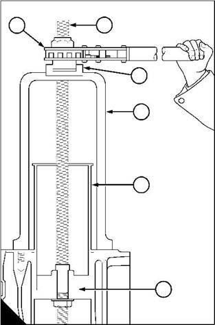
7 Put the tool (A4) on the top face of the cylinder block and over the centre of the cylinder liner (A5). Ensure that the base of the tool is not on top of the flange of the next cylinder liner. |
|
8 Put the bearing (A3) in the top of the tool with the face of the bearing to the bottom of the recess. |
|
2 |
|
1 |
|
3 |
|
4 |
|
5 |
|
6 |
|
A |
|
W085/1 |
|
Continued |
|
106 |
|
Workshop Manual, TPD 1353E, Issue 3 |
|
This document has been printed from SPI². Not for Resale |
![]()
![]()
![]()
![]()

|
7 |
|
Peregrine EDi and 1300 Series EDi |
|
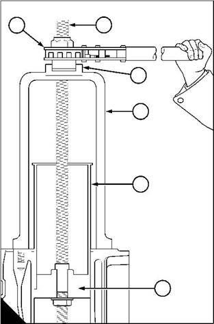
9 Fit the threaded rod (B1) through the bearing and the top of the tool until the handle (B2) is in the recess in the top of the bearing. In this position adjust the threaded rod until the end is below the bottom of the cylinder liner. |
|
10 Fit the adaptor 21825956 (B6) onto the threaded rod and against the bottom of the cylinder liner. 11 Ensure that the two lugs on the top of the adaptor engage with the flats on the threaded rod. 12 Fit the washer and nut and tighten the nut onto the adaptor. |
|
13 Lubricate the ratchet of the handle and the threaded rod with shell spirax or an equivalent oil. Operate the handle to pull the cylinder liner out of the top of the cylinder block. |
|
2 |
|
1 |
|
3 |
|
4 |
|
5 |
|
6 |
|
B |
|
W085/1 |
|
Workshop Manual, TPD 1353E, Issue 3 |
|
107 |
|
This document has been printed from SPI². Not for Resale |
![]()
![]()
|
7 |
|
Peregrine EDi and 1300 Series EDi |
|
To fit |
|
Operation 7-4 |
|
Special requirements |
|
Special tools |
|
Description |
|
Part number |
|
Cylinder liner retainer kit |
|
21825959 |
|
If the original cylinder liner is to be fitted it must be rotated 90° from its original position to put the worn area away from the thrust face. |
|
1 Clean thoroughly the parent bore and the cylinder liner. It is important that the recess for the flange of the cylinder liner is clean, and that the flange of the cylinder liner is also clean. |
|
2 Fit new seals to the cylinder liner. Ensure that the seals are fitted correctly in their grooves. |
|
3 Lightly lubricate the parent bore, the cylinder liner and the new seals with clean engine lubricating oil. |
|
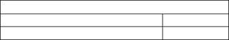
4 Engage the cylinder liner in the parent bore. Ensure that the cylinder liner is vertical and push the liner fully into the cylinder block by hand (B). Ensure that there is no distortion of the liner seals. |
|
5 Fit the retainer kit 21825959, (A) for the cylinder liner. Tighten the three setscrews gradually and evenly to 55 Nm (40 lbf ft) 5,53 kgf m. Further tighten the three setscrews gradually and evenly to 110 Nm (80 lbf ft) 11,06 kgf m. |
|
6 Measure the inside diameter of the cylinder liner, see Operation 7-5. |
|
Note: If the bore is too small this indicates that the liner seal has not seated correctly and has caused distortion of the liner. Remove the liner and fit it again until it is correct. |
|
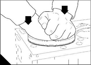
7 Measure the cylinder liner protrusion (A) to ensure that the liner is fitted correctly. Take one measurement between each of the three clamps of the retainer kit. Set the dial test indicator to zero on the top face of the cylinder block before each measurement. The correct protrusion of the cylinder liner is 0,05/0,13 mm (0.002/ 0.006 in). |
|
8 Remove the retainer kit 21825959. |
|
9 Fit the pistons and connecting rods, see Operation 4-5. 10 Fit the cylinder head, see Operation 3-9. 11 Fit the lubricating oil sump, see Operation 10-10. 12 Fill the cooling system to the correct level. |
|
13 Fill the lubricating oil system to the correct level with an approved lubricating oil, see Chapter 5 in the User’s Handbook. |
|
A |
|
B |
|
W054/1 |
|
W140 |
|
108 |
|
Workshop Manual, TPD 1353E, Issue 3 |
|
This document has been printed from SPI². Not for Resale |
![]()
![]()
![]()
![]()
|
7 |
|
Peregrine EDi and 1300 Series EDi |
|
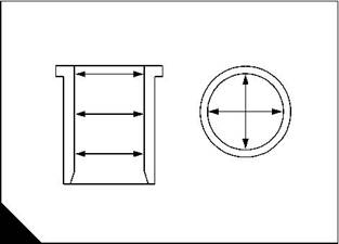
To inspect |
|
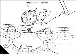
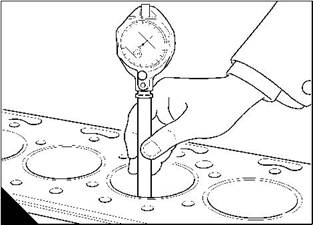
Check the cylinder liners for damage and wear |
|
Operation 7-5 |
|
To check the wear of the cylinder liner see (A) and (B) and compare the results with the relevant Data and dimensions for the "Cylinder liners" on page 16. |
|
A |
|
B |
|
W017 |
|
W040 |
|
Workshop Manual, TPD 1353E, Issue 3 |
|
109 |
|
This document has been printed from SPI². Not for Resale |
![]()
![]()
![]()
![]()
|
This page is intentionally blank |
|
This document has been printed from SPI². Not for Resale |
|
Peregrine EDi and 1300 Series EDi |
|
8 |
|
Engine timing |
|
8 |
|
General description |
|
The marked teeth of the crankshaft gear, the camshaft gear and the two idler gears will be in mesh when number 1 piston is at TDC on the compression stroke. The marked teeth of the idler gears may not necessarily be in mesh, in this position, because of the different speeds at which the gears rotate. |
|
With all of the marks aligned, the crankshaft will require 37 revolutions for all of the marks to align again. There are no timing marks on the gear for the high-pressure pump. |
|
Workshop Manual, TPD 1353E, Issue 3 |
|
111 |
|
This document has been printed from SPI². Not for Resale |
![]()
![]()
|
8 |
|
Peregrine EDi and 1300 Series EDi |
|
Engine timing |
|
To set number 1 cylinder to TDC on the compression stroke |
|
Operation 8-1 |
|
1 Remove the rocker cover, see Operation 3-1. |
|
2 Slowly rotate the crankshaft clockwise, from the front, until the timing mark on the pulley / damper assembly aligns with the pointer on the timing case. |
|
3 Check that the push rods of number 1 cylinder are free to rotate. Number 1 piston is now at TDC on the compression stroke. |
|
Note: If the push rods are not free to rotate, this indicates that number 1 cylinder is on the exhaust stroke. Rotate the crankshaft one turn and align the timing marks. |
|
112 |
|
Workshop Manual, TPD 1353E, Issue 3 |
|
This document has been printed from SPI². Not for Resale |
![]()
![]()
![]()
![]()
|
8 |
|
Peregrine EDi and 1300 Series EDi |
|
To check the valve timing (with a feeler gauge) |
|
Operation 8-2 |
|
1 Set the piston of number 1 cylinder to TDC on the compression stroke, see Operation 8-1. 2 Set the valve tip clearance of number one inlet valve to 0,74 mm (0.029 in). |
|
3 Rotate the crankshaft clockwise, from the front, until number one exhaust valve has just opened. |
|
4 Put a 0,10 mm (0.004 in) feeler gauge between the valve stem and the rocker lever of number one inlet valve. |
|
5 Slowly rotate the crankshaft clockwise, from the front, until the feeler gauge is tight. This is the point where the inlet valve of number one cylinder will begin to open. The timing mark on the pulley / damper assembly should be at 24.5° ± 3.5° BTDC. If the valve timing is correct set the valve tip clearance of number one inlet valve to 0,64 mm (0.025 in). |
|
6 Fit the rocker cover, see Operation 3-2. |
|
7 If the reading in step 5 is incorrect, remove the timing case cover, see Operation 6-1. Check the timing marks on the timing gears. |
|
Note: Adjustment of the timing by one tooth on the timing gears = 11° or 30 mm (1.2 in) on the circumference of the pulley / damper assembly. |
|
Workshop Manual, TPD 1353E, Issue 3 |
|
113 |
|
This document has been printed from SPI². Not for Resale |
![]()
![]()
![]()
![]()
|
8 |
|
Peregrine EDi and 1300 Series EDi |
|
To check the valve timing (with a dial test indicator) |
|
Operation 8-3 |
|
1 Set the piston of number 1 cylinder to TDC on the compression stroke, see Operation 8-1. 2 Set the valve tip clearance of number one inlet valve to 0,74 mm (0.029 in). 3 Set a dial test indicator to zero against the valve rotator of number one inlet valve. |
|
4 Slowly rotate the crankshaft clockwise, from the front, one full turn. The reading on the dial indicator should be 3,93/5,59 mm (0.155/0.220 in). If the reading is correct, set the valve tip clearance of number one inlet valve to 0,64 mm (0.025 in). |
|
5 Remove the dial test indicator. |
|
6 Fit the rocker cover, see Operation 3-2. |
|
7 If the reading in step 4 is incorrect, remove the timing case cover, see Operation 6-1. Check the timing marks on the timing gears. |
|
Note: Adjustment of the timing by one tooth on the timing gears = 11° or 30 mm (1.2 in) on the circumference of the pulley / damper assembly. |
|
114 |
|
Workshop Manual, TPD 1353E, Issue 3 |
|
This document has been printed from SPI². Not for Resale |
![]()
![]()
![]()
![]()
|
Peregrine EDi and 1300 Series EDi |
|
9 |
|
Turbocharger |
|
9 |
|
General description |
|
Warning! Turbochargers operate at high speed and at high temperatures. Keep fingers, tools and other objects away from the inlet and outlet ports of the turbocharger and avoid contact with hot surfaces. |
|
A turbocharger, is fitted between the exhaust and induction manifolds. The turbocharger is driven by exhaust gases and supplies air to the engine at more than atmospheric pressure. The turbocharger is lubricated by oil from the oil filter head. The oil passes through the bearing housing of the turbocharger and returns to the lubricating oil sump. |
|
Some turbochargers are fitted with a waste-gate unit. This unit, which is controlled by boost pressure, allows some of the exhaust gases to by-pass the turbine rotor at higher engine speeds. With this arrangement, the turbocharger can be designed to be more effective at lower engine speeds. |
|
Always use the manufacturer’s instructions and specialist assistance to fit the service kit for the turbocharger. |
|
Caution: Do not use a caustic solution to clean the components of the turbocharger because the turbocharger will be damaged. |
|
Workshop Manual, TPD 1353E, Issue 3 |
|
115 |
|
This document has been printed from SPI². Not for Resale |