 English
 Espaol
 Franais
 阿拉伯
阿拉伯 中文
中文 Deutsch
 Italiano
 Português
 日本
日本 韩国
韩国 български
 hrvatski
 esky
esky Dansk
Dansk Nederlands
 suomi
suomi Ελληνικ
 印度
印度 norsk
norsk Polski
 Roman
Roman русский
 Svenska
Perkins珀金斯1306-E87TA86柴油发动机1830346 C95汽缸盖、1842913 C1进排气门、1830712 C1气门座圈供应商,Perkins珀金斯1306-E87TA86柴油发动机1830346 C95汽缸盖、1842913 C1进排气门、1830712 C1气门座圈技术价格规格咨询服务,Perkins珀金斯1306-E87TA86柴油发动机1830346 C95汽缸盖、1842913 C1进排气门、1830712 C1气门座圈零配件供应,Perkins珀金斯1306-E87TA86柴油发动机1830346 C95汽缸盖、1842913 C1进排气门、1830712 C1气门座圈售后服务中心,Perkins珀金斯1306-E87TA86柴油发动机1830346 C95汽缸盖、1842913 C1进排气门、1830712 C1气门座圈,Perkins珀金斯1306-E87TA86柴油发动机1830346 C95汽缸盖、1842913 C1进排气门、1830712 C1气门座圈详细的技术参数,

产品中心
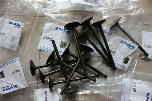
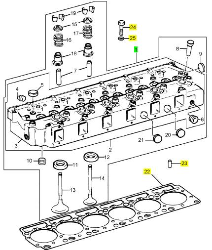
Perkins珀金斯1306-E87TA86柴油发动机1830346 C95汽缸盖、1842913 C1进排气门、1830712 C1气门座圈
详细描述
项目 零配件号码 新件号 描述
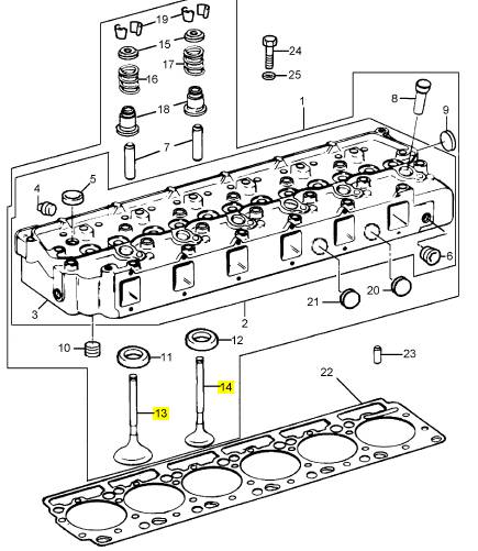
1 1830346 C95 1 1830346 C95 汽缸盖组合
1 1830346 C92 1 1830346 C95 汽缸盖组合
1 1830346 C92 1 1830346 C95 汽缸盖组合
1 1830346 C94 1 1830346 C95 汽缸盖组合
(1) 599992 C91R 1 1830346 C95 汽缸盖装备 -EXCH
22 1830189 C2 1 1830189 C2 密封垫片 - 汽缸盖
22 1830189 C1 1 1830189 C2 密封垫片 - 汽缸盖
23 2 合钉
24 1824954 C2 20 1824954 C3 螺拴
25 1814757 C2 20 1814757 C2 垫圈
项目 零配件号码 新件号 描述
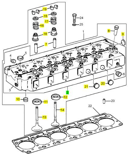
2 1830345 C93 1 1830346 C95 汽缸盖装备
7 1824647 C1 12 1824647 C1 气门导管
8 1818778 C3 6 1818778 C3 套筒
9 445751 6 445751 栓塞
10 444612 1 444613 栓塞
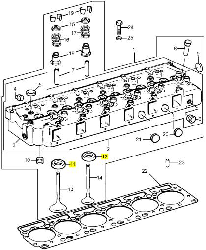
11 1827121 C2 6 1827121 C2 气门座圈
(11) 1830310 C2 6 1830310 C2 气门座圈
(11) 1830311 C2 6 1830311 C2 气门座圈
12 1830711 C1 6 1830711 C1 气门座圈
(12) 1830712 C1 6 1830712 C1 气门座圈
(12) 1830713 C1 6 1830713 C1 气门座圈
13 1842913 C1 6 1842913 C1 进气门
14 1842912 C1 6 1842912 C1 排气阀
15 1824680 C1 12 1824680 C1
16 677349 C1 1 677349 C1 阀弹簧
17 1825540 C1 1 1825540 C1 阀弹簧
18 1823925 C1 12 1823925 C1 气门油封
19 1824644 C1 24 1824644 C1 键
20 23623 R1 1 23623 R1 栓塞
21 347822 R1 1 347822 R1 栓塞
项目 零配件号码 新件号 描述
11 1821901 C1 1 1821901 C1 嵌入内冷铁
11 1821902 C1 1 1821902 C1 嵌入内冷铁
12 1821904 C3 1 1821904 C3 嵌入内冷铁
12 1821905 C3 1 1821905 C3 嵌入内冷铁
项目 零配件号码 新件号 描述
13 1826471 C2 6 1842913 C1 进气门
14 1824840 C2 6 1842912 C1 排气阀
项目 零配件号码 新件号 描述
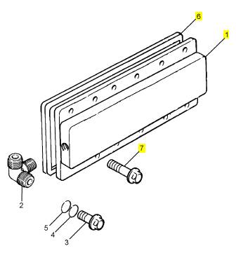
1 1829825 C92 1 1829825 C92 燃油岐管
1 1829825 C91 1 1829825 C92 燃油岐管
6 1822577 C1 1 1822577 C1 密封垫片 -岐管
7 1817959 C1 12 1817959 C1 公制的螺拴
|
Turbocharger |
|
To remove |
|
Operation 9-1 |
|
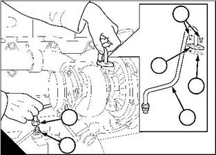
Warning! Turbochargers operate at high speed and at high temperatures. Keep fingers, tools and other objects away from the inlet and outlet ports of the turbocharger and avoid contact with hot surfaces. |
|
1 Thoroughly clean the turbocharger. |
|
2 Remove the air cleaner hose at the compressor inlet. |
|
3 Remove the hose from the compressor outlet. |
|
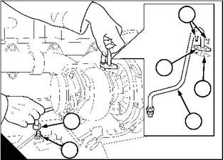
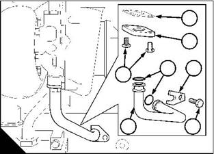
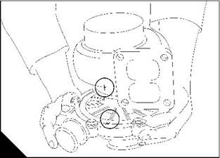
4 Release the setscrews (A1) from the flange (A2) of the oil supply pipe (A4) at the top of the bearing housing. |
|
5 Release the union nut / connection (A6) at the other end of the pipe on the oil filter head. Use a spanner to hold the union (A5) on the filter head when the union nut is released. |
|
6 Remove the pipe and discard the flange joint (A3). |
|
7 Remove the setscrews (B7) from the flange (B2) of the oil drain pipe (B5) at the bottom of the bearing housing. |
|
8 Remove the setscrew (B4) and the clamp (B3), at the other end of the pipe. 9 Remove the oil drain pipe and discard its two ’O’ rings (B6) and flange joint (B1). |
|
10 Hold the turbocharger and release the setscrews that retain the turbocharger to exhaust manifold. Remove the turbocharger and discard the gasket. |
|
11 Cover the openings in the manifolds and the pipes to ensure that debris will not enter. |
|
1 |
|
1 2 |
|
2 |
|
6 |
|
3 |
|
7 |
|
3 |
|
6 |
|
4 |
|
5 |
|
4 |
|
A |
|
5 |
|
B |
|
W098 |
|
W099 |
|
116 |
|
Workshop Manual, TPD 1353E, Issue 3 |
|
This document has been printed from SPI². Not for Resale |
![]()
![]()
![]()
![]()
|
9 |
|
Peregrine EDi and 1300 Series EDi |
|
To fit |
|
Operation 9-2 |
|
1 Remove the covers from the pipes and manifolds. |
|
2 Check that the turbocharger inlet and outlet are clean and free from restriction. Check that the turbocharger shaft rotates freely. Also check that the openings in the manifolds and the exhaust pipe are clean and free from restriction. |
|
3 Fit a new gasket to the exhaust manifold to turbocharger flange. |
|
4 Put the turbocharger in position and hold it. Fit and tighten the setscrews to 66 Nm (49 lbf ft) 6,7 kgf m. 5 Put a suitable container under the turbocharger to contain the oil from the oil drain outlet of the turbocharger. 3 6 Pour 140 cm (0.25 pints) of clean engine lubricating oil into the oil supply port of the bearing housing. |
|
7 Fit a new joint (A3) to the oil supply port on the top of the turbocharger. |
|
8 Clean the threads of the union connection (A5 and A6) and apply a thread sealant to the union connection (A5). |
|
9 Put the oil supply pipe (A4) in position, fit, but do not tighten the flange setscrews (A1). 10 Use a spanner to hold the union connection (A5) while the union nut (A6) on the pipe is tightened. 11 Tighten the flange setscrews (A1). |
|
12 Fit the air cleaner hose to the compressor inlet. |
|
13 Fit the compressor outlet hose. |
|
14 Fit a new joint (B1), the flange (B2) and two new ’O’ rings (B6) onto the oil drain pipe (B5). |
|
15 Install the oil drain pipe into its port in the crankcase. Put and hold the flanged end of the oil drain pipe against the oil drain port, at the bottom of the turbocharger. |
|
16 Fit but do not tighten the two flange setscrews (B7). |
|
17 Put the pipe clamp (B3) in position and hold it. Fit but do not tighten the setscrew (B4). 18 Tighten the three setscrews evenly and gradually. |
|
19 Remove the container and dispose of the lubricating oil in a safe place in accordance with local regulations. |
|
1 |
|
1 2 |
|
2 |
|
6 |
|
3 |
|
7 |
|
3 |
|
6 |
|
4 |
|
5 |
|
4 |
|
A |
|
5 |
|
B |
|
W098 |
|
W099 |
|
Workshop Manual, TPD 1353E, Issue 3 |
|
117 |
|
This document has been printed from SPI². Not for Resale |
![]()
![]()
![]()
![]()
|
9 |
|
Peregrine EDi and 1300 Series EDi |
|
To dismantle |
|
Operation 9-3 |
|
Note: The components of the rotating assembly and the components of the bearing housing, except the backplate ’O’ ring, have been withdrawn as service items. If there is a failure of these components, or if they are excessively worn, the complete bearing housing and rotating assembly must be renewed as a unit. |
|
1 Remove the turbocharger from the engine, see Operation 9-1. |
|
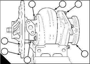
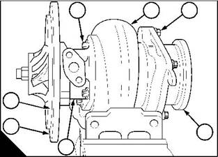
2 Put reference marks (A) on the compressor casing, on the backplate and on the turbine housing to ensure correct assembly later. |
|
3 Hold the turbocharger in a vice that is fitted with soft jaws to protect the turbocharger. |
|
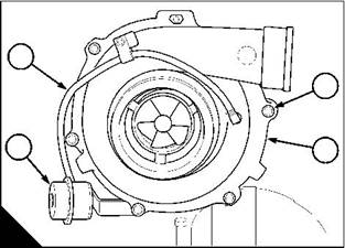
4 Remove the boost sensor pipe (B1) at the waste-gate actuator (B4). Remove the waste-gate actuator and bracket assembly, see Operation 9-7. |
|
5 Remove the six setscrews (B2) that hold the compressor casing (B3) to the backplate (C6), remove the three lock plates. |
|
6 Remove carefully the compressor casing from the turbocharger. If the casing is tight, hit it lightly with a soft faced hammer. |
|
1 |
|
2 |
|
4 |
|
3 |
|
A |
|
B |
|
W100 |
|
W101 |
|
1 |
|
2 |
|
3 |
|
7 |
|
6 |
|
4 |
|
C |
|
5 |
|
W102 |
|
Continued |
|
118 |
|
Workshop Manual, TPD 1353E, Issue 3 |
|
This document has been printed from SPI². Not for Resale |
![]()
![]()
![]()
![]()

|
9 |
|
Peregrine EDi and 1300 Series EDi |
|
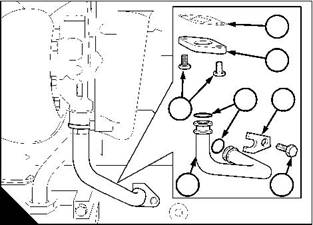
7 Remove the compressor housing seal (D7). |
|
8 To change the angle of the compressor inlet, the casing must be removed completely and then fitted again. Do not turn the casing while it is fitted to the turbocharger because the compressor housing seal will be damaged. |
|
9 Remove the six setscrews (D3) that hold the waste-gate housing (D4) to the turbine casing (D2) and remove the waste-gate housing. |
|
10 Remove the four setscrews (D1) that hold the bearing housing assembly (D5) to the turbine casing, remove the bearing housing assembly. |
|
1 |
|
2 |
|
3 |
|
7 |
|
6 |
|
4 |
|
D |
|
5 |
|
W102 |
|
Workshop Manual, TPD 1353E, Issue 3 |
|
119 |
|
This document has been printed from SPI². Not for Resale |
![]()
![]()

|
9 |
|
Peregrine EDi and 1300 Series EDi |
|
To assemble |
|
Operation 9-4 |
|
1 Fit the waste-gate housing (A4) to the turbine housing (A2), fit and tighten the six setscrews (A3). |
|
2 Fit the bearing housing assembly (A5) to the turbine housing (A2) and align the marks (B). Fit and tighten the four setscrews (A1) to 13,5 Nm (9.6 lbf ft) 1,3 kgf m. |
|
3 Fit the compressor housing seal (A7). |
|
1 |
|
2 |
|
3 |
|
7 |
|
6 |
|
4 |
|
A |
|
5 |
|
B |
|
W102 |
|
W100 |
|
4 Fit the compressor housing to the backplate (A6) and align the marks (B). Fit the three lock plates and the six setscrews (C2). Tighten the setscrews to 21/24 Nm (15.5/17.7 lbf ft) 2,14/2,44 kgf m. |
|
Caution: To change the angle of the compressor inlet, the casing must be removed completely and then fitted again. Do not turn the casing while it is fitted to the turbocharger because the compressor seal will be damaged. |
|
5 Check that the turbine rotates freely. |
|
6 Fit the waste-gate actuator and bracket assembly, see Operation 9-7. Fit the boost sensor pipe. |
|
1 |
|
2 |
|
4 |
|
3 |
|
C |
|
W101 |
|
120 |
|
Workshop Manual, TPD 1353E, Issue 3 |
|
This document has been printed from SPI². Not for Resale |
![]()
![]()
![]()
![]()

|
9 |
|
Peregrine EDi and 1300 Series EDi To inspect |
|
Operation 9-5 |
Caution: Do not straighten the blades of the impeller or the turbine. If they are bent or damaged, the
turbocharger must be renewed.
|
1 Remove the turbocharger, see Operation 9-1. 2 Visually inspect the turbocharger for damage and leaks. 3 Ensure that the turbine shaft turns freely. |
|
4 Check the actuator rod movement, see Operation 9-8. |
|
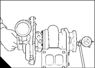
5 Put a dial gauge on the turbocharger (A) to measure the end-float of the turbine shaft. Ensure that the tip of the gauge is in contact with the end of the turbine shaft. Push the shaft fully in one direction and set the gauge to zero. Push the shaft fully in the other direction and record the reading on the gauge. |
|
The correct end-float tolerance is 0,02-0,10 mm (0.001-0.004 in). If the end-float is out of tolerance the turbocharger must be renewed. |
|
A |
|
W103 |
|
To clean the impeller and compressor casing |
|
Operation 9-6 |
|
1 Remove the compressor casing, see Operation 9-3. |
|
2 Put the compressor casing in a suitable container that contains a non-caustic solution. Allow the dirt to become soft and then clean the casing with a hard brush and / or a soft scraper. Dry the casing with clean, compressed air at low pressure. |
|
3 Clean the impeller with a soft brush. |
|
4 Fit the compressor casing, see Operation 9-4. |
|
Workshop Manual, TPD 1353E, Issue 3 |
|
121 |
|
This document has been printed from SPI². Not for Resale |
![]()
![]()
![]()
![]()
![]()
![]()
|
9 |
|
Peregrine EDi and 1300 Series EDi |
|
To remove and to fit the actuator assembly of the waste-gate unit |
|
Operation 9-7 |
|
To remove |
|
Caution: Do not operate the actuator rod by hand, because the calibration of the actuator will be affected. This may cause damage to the engine. |
|
1 Disconnect the boost sensor pipe at the actuator. |
|
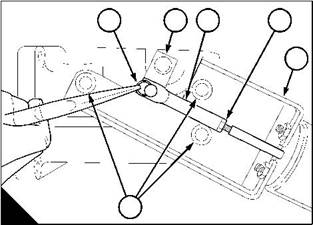
2 Remove the clip (A1) that retains the actuator rod (A3). |
|
3 Release the three setscrews (A6) that retain the waste-gate actuator and bracket assembly (A5) to the turbocharger. |
|
4 Remove the actuator and bracket assembly as a unit, and at the same time, lift the end of the actuator rod off the arm of the waste-gate valve (A2). |
|
To fit |
|
Cautions: |
|
2 |
|
2 |
|
l Do not apply an air pressure of more than 207 kPa (30 lbf/in ) 2,1 kgf/cm to the actuator. Higher pressures |
|
may damage the actuator. |
|
l Do not operate the actuator rod by hand, because the calibration of the actuator will be affected. This may cause damage to the engine. |
|
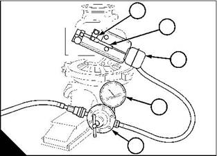
1 Fit the actuator and bracket assembly (A5) to the turbocharger and tighten the three setscrews (A6). Note: Do not put the end of the actuator rod (A3) onto the arm (A2) of the waste-gate valve. |
|
2 Connect the actuator (B3), to an air supply that has a regulator (B5) and an accurate gauge (B4). 3 Operate the arm (B1) of the waste-gate valve by hand to check that the valve is free to move. |
|
4 Push the arm of the waste-gate valve as far as possible toward the actuator and hold the arm in this position. Slowly apply air pressure to the actuator until the end of the actuator rod (B2) will fit easily onto the arm of the waste-gate valve. |
|
5 If the end of the actuator rod will not fit easily onto the arm of the waste-gate valve, the rod of the actuator assembly must be adjusted, see Operation 9-9. |
|
6 Fit the clip (A1). |
|
7 Release the air pressure. |
|
8 Check the operation of the waste-gate unit, see Operation 9-8. |
|
1 |
|
1 |
|
2 |
|
3 |
|
4 |
|
2 |
|
5 |
|
3 |
|
4 |
|
6 |
|
A |
|
B |
|
5 |
|
W057 |
|
W056-1 |
|
122 |
|
Workshop Manual, TPD 1353E, Issue 3 |
|
This document has been printed from SPI². Not for Resale |
![]()
![]()
![]()
![]()
![]()
|
9 |
|
Peregrine EDi and 1300 Series EDi |
|
To check the actuator assembly of the waste-gate unit |
|
Operation 9-8 |
|
Notes: |
|
l If the waste-gate valve does not operate at the correct pressure, it can affect the engine performance. |
|
l If the valve opens at a low pressure, this can cause black exhaust smoke and loss of power at lower engine speeds. |
|
Cautions: |
|
l A high pressure setting can cause high cylinder pressures that can cause failure of the cylinder head gasket and can cause damage to the bearings and pistons. |
|
2 |
|
2 |
|
l Do not apply an air pressure of more than 207 kPa (30 lbf/in ) 2,1 kgf/cm to the actuator. Higher pressures |
|
may damage the actuator. |
|
l Do not operate the actuator rod (A3) by hand, because the calibration of the actuator will be affected, and this may cause damage to the engine. |
|
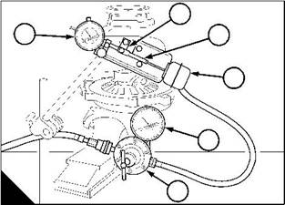
1 Disconnect the boost sensor pipe at the actuator. |
|
2 Connect the actuator to an air supply that has a pressure regulator (A5) and is fitted with an accurate gauge (A4). |
|
3 Fasten a dial gauge (A6) to the turbocharger with its plunger in contact with the end of the actuator rod (A2), to measure the axial movement of the rod. |
|
2 |
|
4 Slowly apply air pressure and check that the rod moves 0,381 mm (0.015 in) at 197 kPa (28.5 lbf in ) |
|
2 |
|
2,0 kgf cm . Ensure that the pointer returns to zero when the pressure is released. |
|
5 Repeat step 4 of the operation several times, to ensure that an accurate reading is obtained |
|
l If the axial movement of the rod is correct, no adjustment is necessary. Remove the air supply and remove the dial gauge. |
|
l If the axial movement of the rod is wrong, adjustment is necessary, see Operation 9-9. Remove the dial gauge. |
|
1 |
|
6 |
|
2 |
|
3 |
|
4 |
|
A |
|
5 |
|
W056 |
|
Workshop Manual, TPD 1353E, Issue 3 |
|
123 |
|
This document has been printed from SPI². Not for Resale |
![]()
![]()
![]()
![]()
![]()
![]()
|
9 |
|
Peregrine EDi and 1300 Series EDi |
|
To adjust the actuator assembly of the waste-gate unit |
|
Operation 9-9 |
|
1 Check the operation of the actuator assembly, see Operation 9-8. |
|
2 With the air pressure still applied, release the locknuts (A4) on the actuator rod. Remove the clip (A1) and lift the actuator rod (A3) from the arm (A2) of the waste-gate valve. |
|
l If the air pressure was too low, turn the end of the actuator rod to reduce its overall length. l If the air pressure was too high, turn the end of the actuator rod to increase its overall length. Note: Turn the end of the actuator rod in half-turn increments. |
|
Caution: Use only the end of the threaded rod to make adjustments. To pull or push the actuator rod could change the calibration of the actuator. The result could be damage to the engine because of too much boost. |
|
1 Put the actuator rod in position on the arm of the waste-gate. 2 Check the operation of the actuator assembly, see Operation 9-8. 3 Repeat the adjustment procedure until the axial movement of the actuator rod is correct. 4 Fit the clip (A1). |
|
5 Tighten the locknuts (A4). |
|
6 Release the air pressure. |
|
1 |
|
2 |
|
3 |
|
4 |
|
5 |
|
6 |
|
A |
|
W057 |
|
124 |
|
Workshop Manual, TPD 1353E, Issue 3 |
|
This document has been printed from SPI². Not for Resale |