 English
 Espaol
 Franais
 阿拉伯
阿拉伯 中文
中文 Deutsch
 Italiano
 Português
 日本
日本 韩国
韩国 български
 hrvatski
 esky
esky Dansk
Dansk Nederlands
 suomi
suomi Ελληνικ
 印度
印度 norsk
norsk Polski
 Roman
Roman русский
 Svenska
Perkins珀金斯1306-E87TA86柴油发动机1873875 C95连杆供应商,Perkins珀金斯1306-E87TA86柴油发动机1873875 C95连杆技术价格规格咨询服务,Perkins珀金斯1306-E87TA86柴油发动机1873875 C95连杆零配件供应,Perkins珀金斯1306-E87TA86柴油发动机1873875 C95连杆售后服务中心,Perkins珀金斯1306-E87TA86柴油发动机1873875 C95连杆,Perkins珀金斯1306-E87TA86柴油发动机1873875 C95连杆详细的技术参数,

产品中心
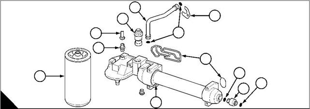
Perkins珀金斯1306-E87TA86柴油发动机1873875 C95连杆、1842570 C92连杆瓦
详细描述
项目 零配件号码 新件号 描述
1 1873875 C95 6 1873875 C95 连杆组合 1514071
1 1830153 C91 6 检查历史 连杆组合 1363043
1 1841615 C91 6 1841634 C93 连杆组合 1363044
1 1841634 C91 6 1841634 C93 连杆组合 1514070 1363044
1 1873875 C92 6 1873875 C95 连杆组合 1514071
1 1873875 C94 6 1873875 C95 连杆组合 1514071
5 1842570 C92 6 1842570 C92 大头轴承装备
5 1842570 C91 6 1842570 C92 大头轴承装备
(5) 1842900 C92 1 1842900 C92 大头 BRG 装备 -U/S
(5) 1842901 C92 1 1842901 C92 大头 BRG 装备 -U/S
(5) 1842902 C92 1 1842902 C92 大头 BRG 装备 -U/S
(5) 1842900 C91 6 1842900 C92 大头 BRG 装备 -U/S
(5) 1842901 C91 6 1842901 C92 大头 BRG 装备 -U/S
(5) 1842902 C91 6 1842902 C92 大头 BRG 装备 -U/S
项目 零配件号码 新件号 描述
2 1 连杆
3 1 连杆小的一端衬套
4 1873884 C2 2 1873884 C2 连杆螺拴
项目 零配件号码 新件号 描述
1 CONROD
1 轴承盖
1817537 C1 2 1840363 C1 螺拴
项目 零配件号码 新件号 描述
1840363 C1 2 1840363 C1 连杆螺拴 1514070
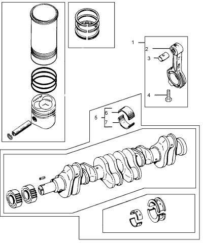
项目 零配件号码 新件号 描述
1822389 C91 6 1822389 C91 大头轴承装备 性疾病。
1830153 C91 6 检查历史 连杆组合 1363043
1833355 C91 1 检查历史 曲轴装备
1841615 C91 6 1841634 C93 连杆组合 1363044
1841634 C91 6 1841634 C93 连杆组合 1514070 1363044
1842570 C91 6 1842570 C92 大头轴承装备
1873875 C92 6 1873875 C95 连杆组合 1514071
1873875 C94 6 1873875 C95 连杆组合 1514071
() 1822486 C91 6 1822486 C91 大头轴承装备
() 1822487 C91 6 1822487 C91 大头轴承装备
() 1822488 C91 6 1822488 C91 大头轴承装备
() 1842900 C91 6 1842900 C92 大头 BRG 装备 -U/S
() 1842901 C91 6 1842901 C92 大头 BRG 装备 -U/S
() 1842902 C91 6 1842902 C92 大头 BRG 装备 -U/S
1 1830596 C91 1 1830596 C91 曲轴装备
1 1833355 C91 1 检查历史 曲轴装备
6 1830725 C91 6 1830725 C91 曲轴轴承装备
6 1833355 C91 1 检查历史 曲轴装备
(6) 1833364 C91 6 1833364 C91 曲轴轴承装备 -U/S
(6) 1833365 C91 6 1833365 C91 曲轴轴承装备 -U/S
(6) 1833366 C91 6 1833366 C91 曲轴轴承装备 -U/S
9 1830726 C91 1 1830726 C91 曲轴轴承装备
9 1833355 C91 1 检查历史 曲轴装备
(9) 1833361 C91 1 1833361 C91 曲轴轴承装备 -U/S
(9) 1833362 C91 1 1833362 C91 曲轴轴承装备 -U/S
(9) 1833363 C91 1 1833363 C91 曲轴轴承装备 -U/S
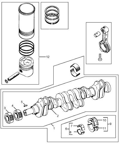
12 6 气缸装备
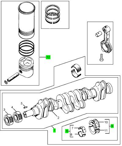
项目 零配件号码 新件号 描述
1833378 C91 1 1842900 C92 连杆轴承 -U/S
1833380 C91 1 1842901 C92 连杆轴承 -U/S
1833381 C91 1 1833381 C91 连杆轴承 -U/S
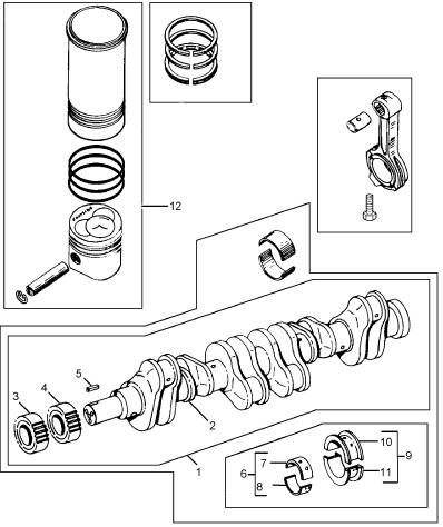
项目 零配件号码 新件号 描述
2 1 曲轴
2 1 曲轴
3 675364 C1 1 675364 C1 油泵传动机构
4 1820299 C1 1 1885883 C1 传动机构
5 17135 R1 1 17135 R1 销
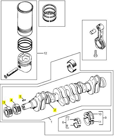
项目 零配件号码 新件号 描述
1833378 C91 1 1842900 C92 连杆轴承 -U/S
1833380 C91 1 1842901 C92 连杆轴承 -U/S
1833381 C91 1 1833381 C91 连杆轴承 -U/S

|
Peregrine EDi and 1300 Series EDi To inspect |
|
Operation 10-4 |
|
1 Visually inspect the filter head and oil cooler assembly for damage and for signs of leakage of coolant or lubricating oil. If there is a leakage from the oil cooler it must be renewed. |
|
2 Inspect the joint and seal faces for damage. |
|
3 Remove the oil temperature control valve (A11), see Operation 10-5, and inspect it for damage. To test the valve, see Operation 10-6. |
|
4 Fit a new ‘O’ ring to the valve and fit the valve. Tighten the valve to 34 Nm (25 lbf ft) 3,5 kgf m. |
|
1 |
|
3 |
|
11 |
|
10 |
|
2 |
|
9 |
|
4 |
|
6 |
|
8 |
|
6 |
|
5 |
|
A |
|
7 |
|
W059 |
|
Workshop Manual, TPD 1353E, Issue 3 |
|
133 |
|
This document has been printed from SPI². Not for Resale |
![]()
![]()
![]()
![]()

|
10 |
|
Peregrine EDi and 1300 Series EDi |
|
Oil temperature control valve |
|
To remove and to fit |
|
Operation 10-5 |
|
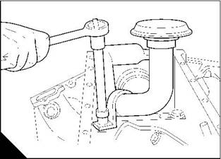
Note: The oil temperature control valve (A11) is fitted into the top of the oil filter head and cooler assembly. |
|
To remove |
|
1 Drain the engine lubricating oil. |
|
2 Remove the oil temperature control valve from the oil filter head and cooler assembly and discard the ‘O’ ring. |
|
To fit |
|
1 Fit a new ‘O’ ring to the valve. |
|
2 Fit the oil temperature control valve and tighten it to 34 Nm (25 lbf ft) 3,5 kgf m. 3 Fill the sump to the correct level with an approved lubricating oil, see Chapter 5 in the User’s Handbook. |
|
1 |
|
3 |
|
11 |
|
10 |
|
2 |
|
9 |
|
4 |
|
6 |
|
8 |
|
6 |
|
5 |
|
A |
|
7 |
|
W059 |
|
To test |
|
Operation 10-6 |
|
1 Hang the valve in a suitable container filled with lubricating oil. |
|
2 Heat the oil gradually. Use a thermometer to check the temperature at which the valve starts to open and at which it is fully open. The correct temperatures are given in the relevant Data and dimensions for the "Oil temperature control valve" on page 17. |
|
134 |
|
Workshop Manual, TPD 1353E, Issue 3 |
|
This document has been printed from SPI². Not for Resale |
![]()
![]()
![]()
![]()
![]()
![]()
|
10 |
|
Peregrine EDi and 1300 Series EDi |
|
Pressure regulating valve |
|
To remove and to fit |
|
Operation 10-7 |
|
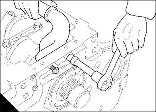
2 Note: The pressure regulating valve (A1) operates at 331 kPa (48 lbf/in ) and is fitted into the crankcase, behind the oil filter head. |
|
To remove |
|
1 Remove the oil filter head and cooler assembly, see Operation 10-2. |
|
2 Push the pressure regulating valve open and insert a piece of copper wire into the valve. Use the copper wire to pull the valve from the crankcase. |
|
To fit |
|
1 Clean the oil filter head and cooler assembly, the joint face on the cylinder block and the coolant inlet and outlet pipes. |
|
2 Fit the pressure regulating valve into position in the crankcase. 3 Fit the oil filter head and cooler assembly, see Operation 10-3. |
|
1 |
|
A |
|
W125 |
|
To inspect |
|
Operation 10-8 |
|
1 Remove the pressure regulating valve, see Operation 10-7. 2 Visually inspect the valve assembly for damage. |
|
Caution: If the pressure regulating valve is damaged, then it must be renewed. |
|
3 Fit a new regulating valve into position in the crankcase, see Operation 10-7. |
|
Workshop Manual, TPD 1353E, Issue 3 |
|
135 |
|
This document has been printed from SPI². Not for Resale |
![]()
![]()
![]()
![]()
![]()
![]()
|
10 |
|
Peregrine EDi and 1300 Series EDi |
|
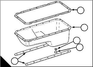
Sump |
|
To remove |
|
Operation 10-9 |
|
1 Operate the engine until it is warm. 2 Stop the engine. |
|
3 Remove the sump drain plug (A4) and discard its sealing washer (A3). Drain the lubricating oil from the sump. |
|
4 Remove the dipstick and dipstick tube. |
|
5 Provide a support for the sump (A2). |
|
6 Remove the 22 setscrews that fasten the sump to the cylinder block, and remove the metal strips (A5). |
|
7 Lower the sump. |
|
8 Remove the joint (A1). |
|
1 |
|
2 |
|
3 4 |
|
5 |
|
A |
|
W061 |
|
136 |
|
Workshop Manual, TPD 1353E, Issue 3 |
|
This document has been printed from SPI². Not for Resale |
![]()
![]()
![]()
![]()

|
10 |
|
Peregrine EDi and 1300 Series EDi To fit |
|
Operation 10-10 |
|
Special requirements Consumable products |
|
Description |
|
Part number |
|
POWERPART Silicon RTV sealing and jointing compound |
|
1861108 |
|
Note: Manufacture locally, four guide dowels. Use the dowels to correctly align the sump, the joint and the metal strips. The dowels should have a thread size of M8 x 1,25, and should have a minimum length of 30 mm. |
|
1 Clean the flange face of the cylinder block. |
|
2 Install the four guide dowels, which have been manufactured locally, into the four corners (B1 and B4) of the cylinder block face. |
|
3 Apply beads of POWERPART Silicon sealing and jointing compound 6 mm (0.25 in) wide, as shown in (B) to: l the timing case (B5) |
|
l the rear oil seal housing (B2) |
|
l around the cup plugs (B3). |
|
Caution: Do not apply the sealant more than five minutes before the sump is to be fitted to the engine. |
|
4 Put the joint (A1) onto the sump, with the bead of sealant toward the cylinder block. 5 Put the sump and the joint in position over the guide dowels, support the sump. |
|
6 Put the metal strips (A5) in position against the sump. Fit 10 of the long setscrews through the metal strips and through the sump to secure them to the cylinder block. Tighten the setscrews finger tight. |
|
7 Fit four of the short setscrews through the sump and into the timing case. Tighten the setscrews finger tight. |
|
8 Fit the other four short setscrews through the sump and into the rear oil seal housing. Tighten the setscrews finger tight. |
|
9 Remove the guide dowels. |
|
1 |
|
1 |
|
2 |
|
5 |
|
2 |
|
3 |
|
3 |
|
4 |
|
4 |
|
4 |
|
5 |
|
A |
|
B |
|
W061 |
|
W066-1 |
|
Continued |
|
Workshop Manual, TPD 1353E, Issue 3 |
|
137 |
|
This document has been printed from SPI². Not for Resale |
![]()
![]()
![]()
![]()
|
10 |
|
Peregrine EDi and 1300 Series EDi |
|
10 Fit the remainder of the long setscrews through the metal strips and through the sump to secure them to the cylinder block. Tighten the setscrews finger tight. |
|
11 Tighten the 22 setscrews to 23 Nm (17 lbf ft) 2,35 kgf m. |
|
12 Fit the drain plug (C4) together with a new sealing washer (C3) and tighten the plug to 68 Nm (50 lbf ft) 7,0 kgf m. |
|
13 Fit the dipstick tube, and fit the dipstick. |
|
14 Fill the lubricating oil sump to the correct level with an approved lubricating oil, see Chapter 5 in the User’s Handbook. |
|
1 |
|
2 |
|
3 4 |
|
5 |
|
C |
|
W061 |
|
138 |
|
Workshop Manual, TPD 1353E, Issue 3 |
|
This document has been printed from SPI². Not for Resale |
![]()
![]()

|
10 |
|
Peregrine EDi and 1300 Series EDi |
|
Oil strainer and suction pipe |
|
To remove and to fit |
|
Operation 10-11 |
|
To remove |
|
Note: The oil strainer is an integral part of the suction pipe. No regular service is necessary, but wash the strainer when it is removed. |
|
1 Drain the engine lubricating oil. |
|
2 Remove the sump, see Operation 10-9. |
|
3 Release the setscrews from the flange (A) of the suction pipe. 4 Release the setscrew from the support bracket (B) of the suction pipe. 5 Remove the setscrews and remove the suction pipe and strainer assembly. 6 Discard the joint. |
|
To fit |
|
1 Clean the flange face of the suction pipe and the joint face of the crankcase. 2 Put the oil strainer and suction pipe, and its new joint in position. 3 Fit and tighten the flange setscrews finger-tight. |
|
4 Fit and tighten the setscrew for the support bracket finger-tight. |
|
Caution: The setscrews of the suction pipe must be tightened evenly and gradually to prevent damage that can be caused by stress. |
|
5 Tighten evenly and gradually all three setscrews to 20 Nm (15 lbf ft) 2,1 kgf m. 6 Fit the sump, see Operation 10-10. |
|
7 Fill the sump to the correct level with an approved lubricating oil, see Chapter 5 in the User’s Handbook. |
|
A |
|
B |
|
W062 |
|
W063 |
|
Workshop Manual, TPD 1353E, Issue 3 |
|
139 |
|
This document has been printed from SPI². Not for Resale |
![]()
![]()
![]()
![]()
|
10 |
|
Peregrine EDi and 1300 Series EDi |
|
Lubricating oil pump |
|
To remove |
|
Operation 10-12 |
|
1 Drain the engine lubricating oil. |
|
2 Remove the crankshaft pulley and damper assembly, see Operation 5-1. 3 Remove and discard the front oil seal, see Operation 10-15. 4 Remove the six setscrews of the oil pump. |
|
Note: There are short setscrews at the 2 o’clock and the 3 o’clock positions. |
|
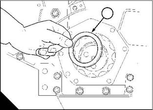
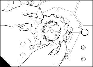
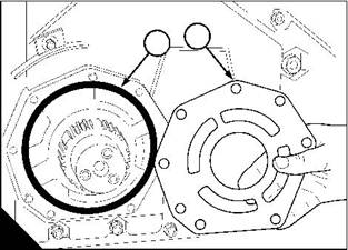
5 Remove the oil pump body (A1) and discard the 'O' ring (A2). 6 Remove the outer rotor (A3). |
|
7 Remove the key (A4). |
|
8 Remove the oil deflector (B1). |
|
1 |
|
1 |
|
4 |
|
2 |
|
3 |
|
A |
|
B |
|
W122 |
|
W123 |
|
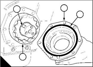
9 Remove the inner rotor (C1). 10 Remove the backplate (D2). |
|
11 Remove and discard the 'O' ring (D1). |
|
2 |
|
1 |
|
1 |
|
C |
|
D |
|
W117 |
|
W116 |
|
140 |
|
Workshop Manual, TPD 1353E, Issue 3 |
|
This document has been printed from SPI². Not for Resale |
![]()
![]()
![]()
![]()
|
10 |
|
Peregrine EDi and 1300 Series EDi |
|
To fit |
|
Operation 10-13 |
|
Special requirements |
|
Special tools Part number |
|
Description |
|
Description |
|
Part number |
|
Front oil seal installer |
|
21825577 |
|
Front oil seal installer adaptor |
|
21825953 |
|
1 Clean the components of the lubricating oil pump and clean the face of the timing case cover. 2 Fit a new front oil seal into the oil pump body, see Operation 10-15. |
|
3 Fit a new 'O’ ring (B1) for the backplate into position in the timing case cover. |
|
4 Lightly lubricate the backplate (B2) with clean engine lubricating oil. Put the backplate into position on the timing case cover. |
|
2 1 |
|
1 |
|
A |
|
B |
|
W117 |
|
W116 |
|
5 Lightly lubricate the inner rotor (A1) with clean engine lubricating oil. Fit the inner rotor. |
|
6 Lightly lubricate the oil deflector (C1) with clean engine lubricating oil. Fit the oil deflector into position on the crankshaft nose. |
|
Note: Fit the oil deflector with the concave side to the inner rotor. |
|
1 |
|
C |
|
W123 |
|
Continued |