 English
 Espaol
 Franais
 阿拉伯
阿拉伯 中文
中文 Deutsch
 Italiano
 Português
 日本
日本 韩国
韩国 български
 hrvatski
 esky
esky Dansk
Dansk Nederlands
 suomi
suomi Ελληνικ
 印度
印度 norsk
norsk Polski
 Roman
Roman русский
 Svenska
Perkins珀金斯1506A柴油发动机T400304启动马达供应商,Perkins珀金斯1506A柴油发动机T400304启动马达技术价格规格咨询服务,Perkins珀金斯1506A柴油发动机T400304启动马达零配件供应,Perkins珀金斯1506A柴油发动机T400304启动马达售后服务中心,Perkins珀金斯1506A柴油发动机T400304启动马达,Perkins珀金斯1506A柴油发动机T400304启动马达详细的技术参数,

产品中心
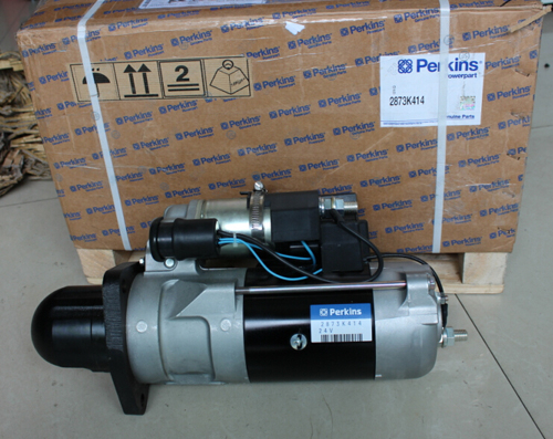
Perkins珀金斯1506A柴油发动机T400304启动马达
详细描述
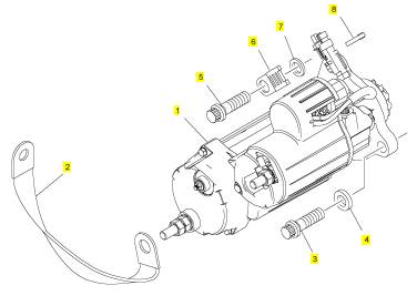
项目 零配件号码 新件号 描述
1 T400304 1 T400304 启动马达
2 T400722 1 T400722 地线
3 T400720 2 T400720 螺拴
4 T400724 2 T400724 垫圈
5 T400720 1 T400720 螺拴
6 T400721 1 T400721 接线夹
7 T400723 1 T400723 垫圈
8 CH10054 1 CH10054 缆拉杆
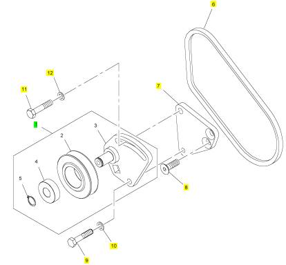
项目 零配件号码 新件号 描述
1 T400548 1 T400548 惰轮皮带轮
6 4590657 1 4590657 皮带
6 T400553 1 T400553 皮带
7 T400554 1 T400554 间隔器
8 T400555 2 T400555 螺旋
9 CH11815 1 CH11815 螺拴
10 CH10277 1 CH10277 垫圈
11 CH11565 1 CH11565 螺拴
12 CH10255 1 CH10255 垫圈
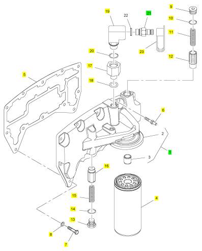
项目 零配件号码 新件号 描述
1 T400614 1 T400614 滤油器座
4 4587260 1 4587260 滤油器
4 T400618 1 T400618 滤油器
5 T400622 1 T400622 密封垫片 - 滤油器的座
6 T400617 1 T400617 图钉
7 CH11565 11 CH11565 螺拴
8 CH10277 12 CH10277 垫圈
9 T400429 1 T400429 栓塞
10 T400188 1 T400188 密封O型圈
11 T400616 1 T400616 弹簧
12 3781 V021 1 3781 V021 阀
13 T400429 1 T400429 栓塞
14 T400188 1 T400188 密封O型圈
15 T400616 1 T400616 弹簧
16 3781 V021 1 3781 V021 阀
17 T400619 1 T400619 承接器
18 T409314 1 T409314 密封O型圈
19 T400620 1 T400620 肘管
20 CH11880 1 CH11880 密封O型圈
21 T400621 1 T400621 停机电磁阀
23 2658 A101 1 2658 A101 帽
|
Fuel injector units |
|
The fuel injector units are controlled electronically by the engine control module, with a pulse of 110 volts, to a solenoid. |
|
The units are actuated by engine lubricating oil from the high-pressure system. |
|
The value of the oil pressure can be altered by the engine management system, this pressure is known as “injection control pressure”. |
|
The injector unit has two main chambers: the oil chamber and the fuel chamber. |
|
The oil chamber receives engine oil from the supply manifold at injection control pressure. A valve, which is connected to the armature of the solenoid, controls the flow of oil through the oil chamber. |
|
l When the solenoid is energised, the valve closes an outlet port and opens an inlet port. l When the solenoid is de-energised, the valve opens the outlet port and closes the inlet port. |
|
The fuel chamber receives fuel at supply pressure from the supply manifold. A ball-valve and a flat-valve control the flow of fuel through the chamber. |
|
160 |
|
Workshop Manual, TPD 1353E, Issue 3 |
|
This document has been printed from SPI². Not for Resale |
![]()
![]()
|
11 |
|
Peregrine EDi and 1300 Series EDi |
|
Fuel injection cycle |
|
There are three phases of injection: |
|
l Phase 1 - Injection (see page 162) l Phase 2 - End-of-injection (see page 163) l Phase 3 - Fill (see page 164) |
|
These occur during the two strokes of the piston. |
|
l The injection phase occurs during the down stroke of the piston. |
|
l The end-of-injection phase and the fill phase occur during the up stroke of the piston. |
|
Key to the colours in the illustrations |
|
Green Blue |
|
Lubricating oil at injection control pressure Lubricating oil at discharge pressure |
|
Yellow Red |
|
Fuel at supply pressure |
|
Fuel at injection pressure |
|
Grey |
|
A moving component, the direction of movement is shown by an arrow on the component |
|
Workshop Manual, TPD 1353E, Issue 3 |
|
161 |
|
This document has been printed from SPI². Not for Resale |
![]()
![]()
|
11 |
|
Peregrine EDi and 1300 Series EDi |
|
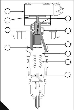
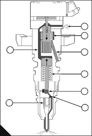
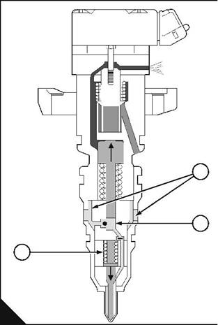
Phase 1: Injection |
|
An electrical pulse from the engine control module energises the solenoid (A1). The armature (A2) of the solenoid pulls the valve (A3) against the pressure of the spring (A6), to close the outlet port (A5), and to open the inlet port (A7). This allows engine oil at injection control pressure to enter the oil chamber (A4). |
|
The oil pressure above the piston is now greater than the total pressure of the spring (A9) and the fuel below the piston (A8), this causes the piston to move down into the fuel chamber (A10). |
|
Note: The surface area of the top of the piston is six or seven times greater than the surface area of the bottom of the piston. This difference gives a mechanical advantage. The mechanical advantage is 6:1 for WK, WL, WP and WQ engines, and is 7:1 for WM, WN, WR and WS engines. An increase of pressure in the oil chamber causes an increase of pressure in the fuel chamber that is six or seven times greater. |
|
As the piston moves down into the fuel chamber, the pressure of the fuel below the piston increases. When this pressure is greater than the supply pressure (B3), the ball-valve (B4) in the fuel chamber closes. This prevents the entry of more fuel into the chamber. |
|
When the ball-valve closes, the pressure in the fuel chamber rises rapidly and the flat valve (B5) opens to allow the high-pressure fuel into the nozzle (B6) of the injector unit. |
|
As the piston continues to move down, more oil enters the oil chamber and the pressure in the fuel chamber continues to increase. When the fuel reaches injection pressure, the nozzle needle (B2) is pushed up from its seat, against the pressure of the spring (B1), and injection begins. |
|
The period of injection is controlled by the engine control module. |
|
1 2 |
|
5 |
|
3 |
|
6 7 |
|
4 |
|
8 9 |
|
3 4 |
|
10 |
|
1 2 |
|
5 6 |
|
A |
|
B |
|
PW239 |
|
PW240 |
|
162 |
|
Workshop Manual, TPD 1353E, Issue 3 |
|
This document has been printed from SPI². Not for Resale |
![]()
![]()
|
11 |
|
Peregrine EDi and 1300 Series EDi |
|
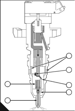
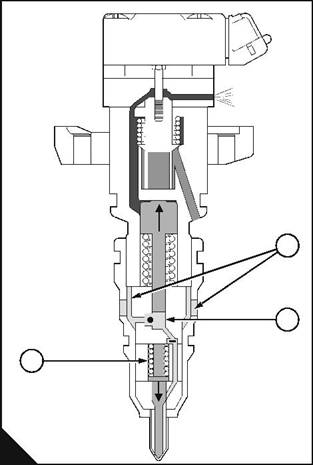
Phase 2: End-of-injection |
|
The engine control module de-energises the solenoid to start the end-of-injection. |
|
When the solenoid is de-energised, the pressure of the spring (C4) moves the valve up, this closes the oil inlet port (C5), and opens the oil outlet port (C3). The oil chamber is now closed to oil at injection control pressure and the oil pressure in the chamber is allowed to discharge through the outlet port into the rocker cover. |
|
When the pressure in the oil chamber is less than the total pressure of the spring (C6) and the fuel in the fuel chamber, the piston moves up into the oil chamber. |
|
When the piston moves up, the pressure of the fuel in the fuel chamber reduces rapidly. This causes the flat valve to close. As the piston continues to move up, the fuel pressure above the flat-valve becomes less than the fuel pressure below it and the valve is kept closed. |
|
The initial rapid reduction of pressure in the fuel chamber allows the spring (D1) to close the nozzle needle. As soon as the nozzle needle closes it fills more space in the nozzle, which causes the pressure below the flat valve to increase rapidly. This opens the nozzle needle again and a small amount of fuel is injected, then the pressure reduces again and the nozzle needle closes. Fuel injection ends. |
|
3 4 |
|
1 |
|
5 |
|
2 |
|
6 |
|
7 |
|
3 |
|
2 1 8 |
|
C |
|
D |
|
PW241 |
|
PW242 |
|
Workshop Manual, TPD 1353E, Issue 3 |
|
163 |
|
This document has been printed from SPI². Not for Resale |
![]()
![]()
|
11 |
|
Peregrine EDi and 1300 Series EDi |
|
Phase 3: Fill |
|
When the piston moves up during the end-of-injection phase, the pressure in the fuel chamber (E3) reduces. When this pressure is less than supply pressure (E2), the ball valve opens, and fuel is allowed to fill the fuel chamber through holes in the side of the injector unit. The flat-valve is closed by the pressure of the fuel below it. |
|
2 |
|
3 |
|
1 |
|
E |
|
PW242 |
|
164 |
|
Workshop Manual, TPD 1353E, Issue 3 |
|
This document has been printed from SPI². Not for Resale |
![]()
![]()
|
11 |
|
Peregrine EDi and 1300 Series EDi |
|
Fuel filter |
|
To renew the fuel strainer and the canister of the fuel filter |
|
Operation 11-1 |
|
Fuel pre-filter |
|
This will normally be fitted between the fuel tank and the engine. Check the filter bowl for water at regular intervals and drain as necessary. Refer to the User’s Handbook for the correct service intervals. |
|
Caution: It is important that only the genuine Perkins parts are used. The use of incorrect parts could damage the HEUI fuel injectors. |
|
Note: The fuel filter assembly has a fuel strainer to remove the larger particles from the fuel and a filter canister to remove the smaller particles. The fuel strainer and the filter canister should be renewed at the same time. |
|
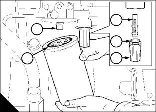
1 Thoroughly clean the outer surfaces of the fuel filter assembly. |
|
2 Use a strap wrench or similar tool to loosen the filter canister, and remove the canister. |
|
1 |
|
3 Use a 29 mm (1 / in) socket spanner to remove the plastic cover (A5) from the fuel strainer. Remove the |
|
8 |
|
strainer (A3) and the ’O’ ring (A4) from the cover. |
|
4 Fit a new strainer and a new ’O’ ring to the cover and fit the cover to the filter head. Caution: Ensure that the open end of the new strainer is toward the filter head. |
|
5 Ensure that the threaded adaptor (A1) is secure in the filter head and that the inside of the head is clean. |
|
Lubricate lightly the seal (A2) of the new canister with clean diesel fuel. Fit the new canister to the filter head |
|
1 |
|
and tighten the canister by hand until the seal contacts the filter head. Tighten the canister a further / turn by |
|
2 |
|
hand. Do not use a strap wrench. |
|
6 Eliminate the air from the fuel filter, see Operation 11-9. |
|
3 |
|
1 |
|
4 |
|
2 |
|
5 |
|
A |
|
W009 |
|
Workshop Manual, TPD 1353E, Issue 3 |
|
165 |
|
This document has been printed from SPI². Not for Resale |
![]()
![]()
![]()
![]()
|
11 |
|
Peregrine EDi and 1300 Series EDi |
|
Fuel injector units |
|
To remove |
|
Operation 11-2 |
|
A faulty fuel injector unit can cause an engine misfire. |
|
Cautions: |
|
l Special equipment is necessary to test the fuel injector units. This equipment is available at Perkins distributors. |
|
l Fuel injector units should be removed by a person who has had the correct training. If the correct procedure is not used, the cylinders of the engine will be filled with fuel and engine lubricating oil. |
|
The fuel injector units are controlled by the engine management system, which cannot be adjusted by the operator. |
|
1 Put a container of approximately 2 litres (4 pints) capacity under the drain plug (A2) of the supply manifold. |
|
2 Remove the banjo bolt (B3) of the fuel return pipe, and disconnect the banjo union (B2). Discard the copper washers. |
|
3 Remove the valve (B1) for the fuel return pipe and drain the fuel from the gallery in the supply manifold (A3). |
|
4 Remove the plug (A2) and drain the lubricating oil from the gallery in the supply manifold (A3). Remove and discard the ‘O’ ring (A1). |
|
1 |
|
2 |
|
1 |
|
3 |
|
2 |
|
3 |
|
A |
|
B |
|
W212 |
|
W213 |
|
Continued |
|
166 |
|
Workshop Manual, TPD 1353E, Issue 3 |
|
This document has been printed from SPI². Not for Resale |