 English
 Espaol
 Franais
 阿拉伯
阿拉伯 中文
中文 Deutsch
 Italiano
 Português
 日本
日本 韩国
韩国 български
 hrvatski
 esky
esky Dansk
Dansk Nederlands
 suomi
suomi Ελληνικ
 印度
印度 norsk
norsk Polski
 Roman
Roman русский
 Svenska
Perkins珀金斯1506A柴油发动机T400950涡轮增压器供应商,Perkins珀金斯1506A柴油发动机T400950涡轮增压器技术价格规格咨询服务,Perkins珀金斯1506A柴油发动机T400950涡轮增压器零配件供应,Perkins珀金斯1506A柴油发动机T400950涡轮增压器售后服务中心,Perkins珀金斯1506A柴油发动机T400950涡轮增压器,Perkins珀金斯1506A柴油发动机T400950涡轮增压器详细的技术参数,

产品中心
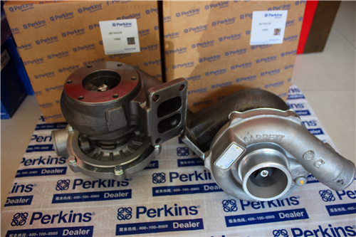
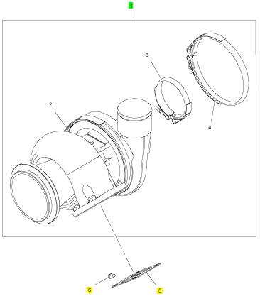
Perkins珀金斯1506A柴油发动机T400950涡轮增压器
详细描述
项目 零配件号码 新件号 描述
1 T400950 1 T400950 涡轮增压器
(1) T400950R 1 T400950R 涡轮增压器 -交换
5 T400948 1 T400948 密封垫片 -涡轮增压器
6 CH11242 4 CH11242 锁紧螺母
|
Peregrine EDi and 1300 Series EDi |
|
5 Remove the container and dispose of the fluids safely in accordance with local regulations. 6 Remove the rocker cover, see Operation 3-1. |
|
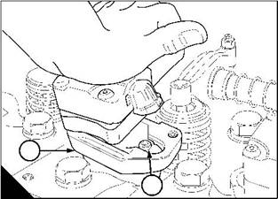
7 Remove the screws that retain the plate for the electrical cables, and remove the plate (C). 8 Remove the front setscrew (D) from the clamp that retains the injector unit. |
|
C |
|
D |
|
W218 |
|
W219 |
|
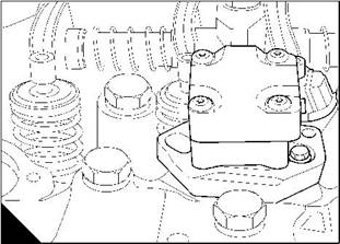
Caution: Do not remove the rear shouldered setscrew (E1), it is not necessary to do so. 9 Tilt the clamp (F) until it is free from the rear shouldered setscrew. |
|
1 |
|
E |
|
F |
|
W220/1 |
|
W221/1 |
|
Continued |
|
Workshop Manual, TPD 1353E, Issue 3 |
|
167 |
|
This document has been printed from SPI². Not for Resale |
![]()
![]()

|
11 |
|
Peregrine EDi and 1300 Series EDi |
|
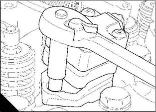
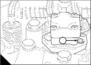
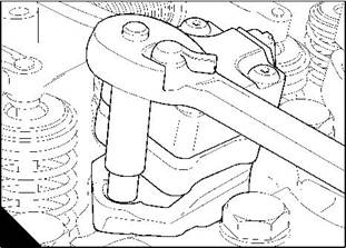
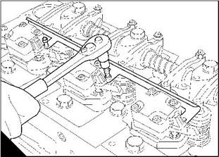
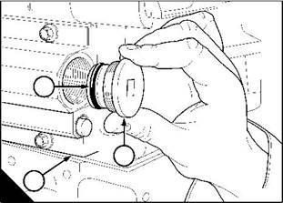
10 Push the clamp toward the rear of the engine (G). 11 Use a lever (H) to carefully raise the injector unit. 12 Remove the injector unit. |
|
13 Remove and discard the ‘O’ rings and the washer, see Operation 11-4. |
|
G |
|
H |
|
W222 |
|
W223 |
|
168 |
|
Workshop Manual, TPD 1353E, Issue 3 |
|
This document has been printed from SPI². Not for Resale |
![]()
![]()
|
11 |
|
Peregrine EDi and 1300 Series EDi |
|
To fit |
|
Operation 11-3 |
|
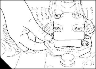
1 Renew the injector unit seals and washer, see Operation 11-4. |
|
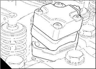
2 Carefully insert the injector unit into its sleeve; ensure that the clamp (A1) is aligned to allow the shouldered rear setscrew (A2) to pass through it. |
|
3 Push the injector unit down (A) until it is on its seat. |
|
4 Tilt the clamp (B) until it is past the head of the rear setscrew. |
|
1 |
|
A |
|
2 |
|
B |
|
W224/1 |
|
W221 |
|
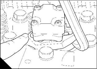
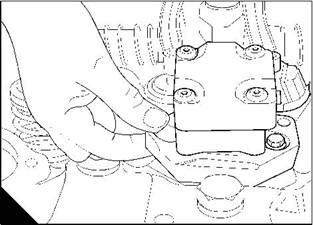
5 Push the clamp towards the front of the engine (C) until it engages the rear shouldered setscrew and aligns with the hole for the front setscrew. |
|
6 Fit the front setscrew (D) and tighten it to 13 Nm (10 lbf ft) 1,3 kgf m. |
|
C |
|
D |
|
W220 |
|
W219 |
|
Continued |
|
Workshop Manual, TPD 1353E, Issue 3 |
|
169 |
|
This document has been printed from SPI². Not for Resale |
![]()
![]()
![]()
![]()
|
11 |
|
Peregrine EDi and 1300 Series EDi |
|
7 Fit the plate for the injector unit cables (E). |
|
8 Fit the rocker cover, see Operation 3-2. |
|
9 Fit a new ‘O’ ring (F1) to the drain plug and fit the plug (F2) into the gallery in the supply manifold (F3). |
|
1 |
|
2 |
|
3 |
|
E |
|
F |
|
W218 |
|
W212 |
|
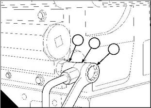
10 Fit the valve (G1) for the fuel return pipe and tighten it to 35 Nm (26 lb ft) 3,6 kgf m. |
|
11 Fit new copper washers to the banjo union (G3) of the fuel return pipe, fit and tighten the banjo bolt (G2) to 35 Nm (26 lb ft) 3,6 kgf m. |
|
12 Eliminate air from the fuel system, see Operation 11-9. |
|
1 2 |
|
3 |
|
G |
|
W213 |
|
170 |
|
Workshop Manual, TPD 1353E, Issue 3 |
|
This document has been printed from SPI². Not for Resale |
![]()
![]()
|
11 |
|
Peregrine EDi and 1300 Series EDi To renew the fuel injector unit seals |
|
Operation 11-4 |
|
To remove the old ‘O’ ring seals and seal rings |
|
1 Remove the injector units, see Operation 11-2. |
|
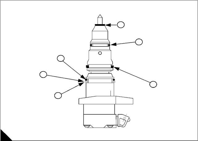
2 Remove the washer (A6) from the injector unit nozzle - copper for WK, WL, WM, and WN engines; stainless steel for WP, WQ, WR, and WS engines. |
|
Cautions: |
|
l ‘O’ rings and seals must be renewed each time a fuel injector is removed. |
|
l If any of the injector units have damaged ’O’ rings or seals, then all injector units must be removed and checked. |
|
l During removal of the ‘O’ rings, be careful to avoid damage to the body of the injector unit or the grooves for the seals. |
|
3 With the use of a suitable smooth tool, lift the lower ‘O’ ring (A5) (orange) out of its groove. Cut the seal and remove it. |
|
4 Lift the middle seal (A4) (blue and black) out of its groove with the same smooth tool, cut and remove it. 5 Lift the upper ‘O’ ring (A3) (blue), cut and remove it. |
|
6 Lift the rubber ring (A2) (black), cut and remove it. |
|
7 Carefully remove the split ring (A1) (steel). |
|
6 |
|
5 |
|
3 |
|
2 |
|
4 |
|
1 |
|
A |
|
W225/1 |
|
Workshop Manual, TPD 1353E, Issue 3 |
|
171 |
|
This document has been printed from SPI². Not for Resale |
![]()
![]()
![]()
![]()
![]()
|
11 |
|
Peregrine EDi and 1300 Series EDi |
|
To fit the ‘O’ rings and ring seals |
|
Ensure the injector unit is clean, then fit the new seals in the sequence below: |
|
Caution: All ‘O’ rings and seals and the injector unit must be lightly lubricated with new clean engine lubricating oil before the ‘O’ rings and seals are fitted. |
|
1 Carefully slide the split ring (B1) (steel) over the injector body and into its groove. |
|
2 Carefully slide the rubber ring (B2) (black) over the injector body until it fits into its groove - ensure that the ring is not damaged. |
|
3 Carefully slide the lubricated ‘O’ ring (B3) (blue) over the injector body until it fits into its groove. 4 Carefully slide the lubricated seal (B4) (blue and black) over the injector body until it fits into its groove. 5 Carefully slide the lubricated lower ‘O’ ring (B5) (orange) over the injector body until it fits into its groove. 6 Fit the washer (B6) to the injector unit: |
|
l copper for WK, WL, WM, and WN engines; |
|
l stainless steel for WP, WQ, WR, and WS engines. |
|
7 The injector units are now ready to be fitted, see Operation 11-3. |
|
6 |
|
5 |
|
3 |
|
2 |
|
4 |
|
1 |
|
B |
|
W225/1 |
|
172 |
|
Workshop Manual, TPD 1353E, Issue 3 |
|
This document has been printed from SPI². Not for Resale |
![]()
![]()

|
11 |
|
Peregrine EDi and 1300 Series EDi |
|
Fuel lift pump |
|
To remove and to fit |
|
Operation 11-5 |
|
To remove |
|
Note: The fuel lift pump is fitted to the side of the high-pressure pump. |
|
1 Remove the banjo bolts (A1 and A5) from the fuel pipes and discard the washers (A2 and A4). 2 Release the nuts (A3) and remove the pump (A6). |
|
3 Remove and discard the joint. |
|
To fit |
|
1 Clean the joint face on the fuel lift pump and on the high-pressure pump. |
|
Note: Ensure that the eccentric on the camshaft of the high-pressure pump is in the minimum lift position. If it is not, rotate the crankshaft until it is. |
|
2 Fit a new joint to the lift pump. |
|
3 Check that the push rod (Operation 11-6/A12) is in position and fit the lift pump to the high-pressure pump. 4 Fit and tighten the nuts (A3) gradually and evenly to 6 Nm (4 lbf ft) 0,6 kgf m. |
|
5 Connect the fuel pipes to the fuel lift pump, fit new copper washers (A2 and A4) to the banjo bolts (A1 and A5). Tighten the banjo bolts to 35 Nm (26 lbf ft) 3,6 kgf m. |
|
3 |
|
5 |
|
1 |
|
4 |
|
2 |
|
A |
|
6 |
|
W129/1 |
|
Workshop Manual, TPD 1353E, Issue 3 |
|
173 |