 English
 Espaol
 Franais
 阿拉伯
阿拉伯 中文
中文 Deutsch
 Italiano
 Português
 日本
日本 韩国
韩国 български
 hrvatski
 esky
esky Dansk
Dansk Nederlands
 suomi
suomi Ελληνικ
 印度
印度 norsk
norsk Polski
 Roman
Roman русский
 Svenska
Perkins珀金斯1600柴油发动机7083062 C92机油泵供应商,Perkins珀金斯1600柴油发动机7083062 C92机油泵技术价格规格咨询服务,Perkins珀金斯1600柴油发动机7083062 C92机油泵零配件供应,Perkins珀金斯1600柴油发动机7083062 C92机油泵售后服务中心,Perkins珀金斯1600柴油发动机7083062 C92机油泵,Perkins珀金斯1600柴油发动机7083062 C92机油泵详细的技术参数,

产品中心
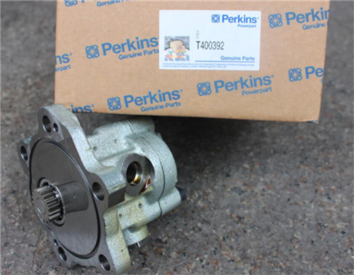
Perkins珀金斯1600柴油发动机7083062 C92机油泵
详细描述
项目 零配件号码 新件号 描述
1 7083062 C91 1 7083062 C92 油泵
15 1833483 C1 2 1833483 C1 螺拴
16 1833482 C1 4 1833482 C1 螺拴
项目 零配件号码 新件号 描述
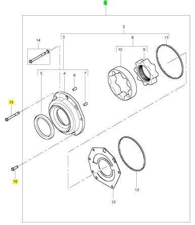
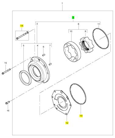
2 1 油泵
12 1880017 C1 1 1880017 C1 板
13 1841350 C1 1 1841350 C1 密封 - 油泵
14 1880074 C1 1 1880074 C1 密封
|
Systems Operation Section |
|
KENR8772 |
|
Communication Adapter Tool – The communication adapter provides a communication link between the ECM and the Electronic Service Tool. |
|
Engine Control Module (ECM) – The ECM is the control computer of the engine. The ECM provides power to the electronics. The ECM monitors data that is input from the sensors of the engine. The ECM acts as a governor in order to control the speed and the power of the engine. |
|
Component Identifier (CID) – The CID is a number that identifies the specific component of the electronic control system that has experienced a diagnostic code. |
|
Electronic Service Tool – The electronic service tool is used for diagnosing various electronic controls. |
|
Coolant Temperature Sensor – The coolant temperature sensor detects the engine coolant temperature for all normal operating conditions and for engine monitoring. |
|
Engine Monitoring – Engine Monitoring is the part of the electronic engine control that monitors the sensors. This also warns the operator of detected problems. |
|
Customer Specified Parameters – A customer specified parameter is a parameter that can be changed in the ECM with the Electronic Service Tool. A customer specified parameter's value is set by the customer. These parameters are protected by customer passwords. |
|
Engine Oil Pressure Sensor – The engine oil pressure sensor measures engine oil pressure. The sensor sends an electronic signal to the ECM that is dependent on the engine oil pressure. |
|
Engine Speed/Timing Sensor – An engine |
|
speed/timing sensor is a Hall effect sensor. The ECM interprets this signal as the crankshaft position and the engine speed. Two sensors are used to provide the speed and timing signals to the ECM. The primary sensor is associated with the crankshaft and the secondary sensor is associated with the camshaft. |
|
Data Link – The Data Link is used for communication with other microprocessor-based devices. |
|
Derate – Certain engine conditions will generate event codes. Also, engine derates may be applied. The map for the engine derate is programmed into the ECM software. The derate can be one or more of three types: reduction of rated power, reduction of rated engine speed, and reduction of rated machine speed for OEM products. |
|
Estimated Dynamic Timing – Estimated dynamic timing is the estimate of the actual injection timing that is calculated by the ECM. |
|
Event Code – An event code may be activated in order to indicate an abnormal engine operating condition. These codes usually indicate a mechanical problem instead of an electrical system problem. |
|
Desired Engine Speed – The desired engine speed is input to the electronic governor within the ECM. The electronic governor uses the signal from the throttle position sensor, the engine speed/timing sensor, and other sensors in order to determine the desired engine speed. |
|
Failure Mode Identifier (FMI) – This identifier indicates the type of failure that is associated with the component. The FMI has been adopted from the SAE practice of J1587 diagnostics. The FMI follows the parameter identifier (PID) in the descriptions of the fault code. The descriptions of the FMIs are in the following list. |
|
Diagnostic Trouble Code – A diagnostic trouble code is sometimes referred to as a fault code. These codes indicate an electronic system malfunction. |
|
Diagnostic Lamp – A diagnostic lamp is sometimes called the check engine light. The diagnostic lamp is used to warn the operator of the presence of an active diagnostic code. The diagnostic lamps are red and orange. The lamp may not be included in all applications. |
|
0 – The data is valid but the data is above the normal operational range. |
|
1 – The data is valid but the data is below the normal operational range. |
|
Direct Current (DC) – Direct current is the type of current that flows consistently in only one direction. |
|
2 – The data is erratic, intermittent, or incorrect. |
|
3 – The voltage is above normal or the voltage is |
|
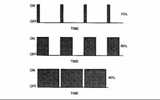
Duty Cycle – See Pulse Width Modulation. |
|
shorted high. |
|
Electronic Engine Control – The electronic engine control is a complete electronic system. The electronic engine control monitors the engine operation under all conditions. The electronic engine control also controls the engine operation under all conditions. |
|
4 – The voltage is below normal or the voltage is shorted low. |
|
5 – The current is below normal or the circuit is open. |
|
6 – The current is above normal or the circuit is grounded. |
|
This document is printed from SPI². Not for RESALE |
![]()
|
KENR8772 |
|
9 Systems Operation Section |
|
7 – The mechanical system is not responding properly. |
|
Intake Manifold Pressure Sensor – The Intake Manifold Pressure Sensor measures the pressure in the intake manifold. The pressure in the intake manifold may be different to the pressure outside the engine (atmospheric pressure). The difference in pressure may be caused by an increase in air pressure by a turbocharger (if equipped). |
|
8 – There is an abnormal frequency, an abnormal pulse width, or an abnormal time period. |
|
9 – There has been an abnormal update. 10 – There is an abnormal rate of change. 11 – The failure mode is not identifiable. 12 – The device or the component is damaged. |
|
J1939 CAN Data Link – Logged diagnostic codes are codes which are stored in the memory. These codes are meant to be an indicator of possible causes for intermittent problems. Refer to the term “Diagnostic Code” in this glossary for more information. |
|
Flash File – This file is software that is inside the ECM. The file contains all the instructions (software) for the ECM and the file contains the performance maps for a specific engine. The file may be reprogrammed through flash programming. |
|
NOx Reduction System – The NOx Reduction System recycles a portion of the exhaust gases back into the inlet air in order to reduce the formation of oxides of nitrogen (NOx) in the combustion process. The recycled exhaust gas passes through a cooler before being introduced into the inlet air. |
|
Flash Programming – Flash programming is the method of programming or updating an ECM with an electronic service tool over the data link. |
|
OEM – OEM is an abbreviation for the Original Equipment Manufacturer. This is the manufacturer of the machine or the vehicle that uses the engine. |
|
Flash Memory – See Programmable Software. |
|
Fuel Ratio Control (FRC) – The FRC is a limit that is based on the control of the fuel to the air ratio. The FRC is used for emission control. When the ECM senses a higher turbocharger outlet pressure, the ECM increases the limit for the FRC in order to allow more fuel into the cylinders. |
|
Open Circuit – An open circuit is a condition that is caused by an open switch, or by an electrical wire or a connection that is broken. When this condition exists, the signal or the supply voltage can no longer reach the intended destination. |
|
Parameter – A parameter is a value or a limit that is programmable. This helps determine specific characteristics or behaviors of the engine. |
|
Fuel Pump – See “Fuel Injection Pump”. |
|
Fuel Injection Pump – This item is sometimes referred to as the Fuel Pump. This is a device that supplies fuel under pressure to the injectors. |
|
Parameter Identifier (PID) – A PID is a numerical code that contains two digits or three digits. A numerical code is assigned to each component. The numerical code identifies data via the data link to the ECM. |
|
Harness – The harness is the bundle of wiring (loom) that connects all components of the electronic system. |
|
Password – A password is a group of numeric characters or a group of alphanumeric characters that is designed to restrict access to parameters. The electronic system requires correct passwords in order to change some parameters (Factory Passwords). Refer to Troubleshooting, “Factory Passwords” for more information. |
|
Hertz (Hz) – Hertz is the measure of frequency in cycles per second. |
|
Inlet Manifold Air Temperature Sensor – The inlet manifold air temperature sensor detects the air temperature in the inlet manifold. The ECM monitors the air temperature and other data in the inlet manifold in order to adjust injection timing and other performance functions. |
|
Programmable Software – The software is programmed into the ECM. The software contains all the instructions (software) for the ECM and the software contains the performance maps for a specific engine. The software may be reprogrammed through flash programming. |
|
Integrated Electronic Controls – The engine is designed with the electronic controls as a necessary part of the system. The engine will not operate without the electronic controls. |
|
Power Cycling – Power cycling refers to the action of cycling the keyswitch from any position to the OFF position, and to the START/RUN position. |
|
This document is printed from SPI². Not for RESALE |
![]()
|
10 |
|
KENR8772 |
|
Systems Operation Section |
|
Primary Speed/Timing Sensor – This sensor determines the position of the crankshaft during engine operation. If the primary speed/timing sensor fails during engine operation, the secondary speed/timing sensor is used to provide the signal. |
|
Short Circuit – A short circuit is a condition that has an electrical circuit that is inadvertently connected to an undesirable point. An example of a short circuit is a wire which rubs against a vehicle frame and this rubbing eventually wears off the wire insulation. Electrical contact with the frame is made and a short circuit results. |
|
Pulse Width Modulation (PWM) – The PWM is a signal that consists of pulses that are of variable width. These pulses occur at fixed intervals. The ratio of “TIME ON” versus total “TIME OFF” can be varied. This ratio is also referred to as a duty cycle. |
|
Signal – The signal is a voltage or a waveform that is used in order to transmit information typically from a sensor to the ECM. |
|
Supply Voltage – The supply voltage is a continuous voltage that is supplied to a component in order to provide the electrical power that is required for the component to operate. The power may be generated by the ECM or the power may be battery voltage that is supplied by the engine wiring. |
|
System Configuration Parameters – System configuration parameters are parameters that affect emissions and/or operating characteristics of the engine. |
|
“T” Harness – This harness is a test harness that is designed to permit normal circuit operation and the measurement of the voltage simultaneously. Typically, the harness is inserted between the two ends of a connector. |
|
g00284479 |
|
Illustration 4 |
|
Rated Fuel Limit – This is a limit that is based on the power rating of the engine and on the engine rpm. The Rated Fuel Limit enables the engine power and torque outputs to conform to the power and torque curves of a specific engine model. These limits are in the flash file and these limits cannot be changed. |
|
Throttle Position – The throttle position is the interpretation by the ECM of the signal from the throttle position sensor or the throttle switch. |
|
Throttle Position Sensor – The throttle position sensor is an electronic sensor that is connected to an accelerator pedal or a hand lever. This sensor sends a signal to the ECM that is used to calculate desired engine speed. |
|
Reference Voltage – Reference voltage is a regulated voltage and a steady voltage that is supplied by the ECM to a sensor. The reference voltage is used by the sensor to generate a signal voltage. |
|
Timing Calibration – The timing calibration is the adjustment of an electrical signal. This adjustment is made in order to correct the timing error between the camshaft and the engine speed/timing sensors or between the crankshaft and the engine speed/timing sensors. |
|
Relay – A relay is an electromechanical switch. A flow of electricity in one circuit is used to control the flow of electricity in another circuit. A small current or voltage is applied to a relay in order to switch a much larger current or voltage. |
|
Secondary Speed/Timing Sensor – This sensor determines the position of the camshaft during engine operation. If the primary speed/timing sensor fails during engine operation, the secondary speed/timing sensor is used to provide the signal. |
|
Top Center Position – The top center position refers to the crankshaft position when the engine piston position is at the highest point of travel. The engine must be turned in the normal direction of rotation in order to reach this point. |
|
Sensor – A sensor is used to detect a change in the pressure, in the temperature, or in mechanical movement. When any of these changes are detected, a sensor converts the change into an electrical signal. |
|
Total Tattletale – The total tattletale is the total number of changes to all the parameters that are stored in the ECM. |
|
Wait To Start Lamp – This is a lamp that is included in the cold starting aid circuit in order to indicate when the wait to start period has expired. The grid heater has not deactivated at this point in time. |
|
This document is printed from SPI². Not for RESALE |
![]()
![]()
|
KENR8772 |
|
11 Systems Operation Section |
|
Wastegate – This is a device in a turbocharged engine that controls the maximum boost pressure that is provided to the inlet manifold. |
|
i04112658 |
|
Electronic Control System Components |
|
Introduction |
|
The 1600 Series industrial engine is designed for electronic control. The engine has an Electronic Control Module (ECM), a high-pressure oil pump and electronic unit injectors. All of these items are electronically controlled. There are also a number of engine sensors. The ECM controls the engine operating parameters through the software within the ECM and the inputs from the various sensors. The software contains parameters that control the engine operation. The parameters include all of the operating maps and customer-selected parameters. |
|
The electronic control system has the following components: |
|
• ECM |
|
• Pressure sensors |
|
• Temperature sensors • Crankshaft position sensor • Camshaft position sensor • Electronic unit injectors |
|
• Valve for the NOx Reduction System (NRS) (if equipped) |
|
This document is printed from SPI². Not for RESALE |
![]()
|
12 |
|
KENR8772 |
|
Systems Operation Section |
|
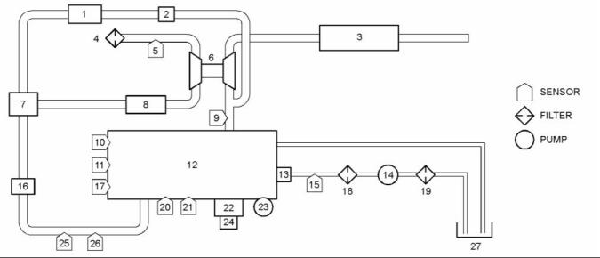
g02734078 |
|
Illustration 5 |
|
Typical example |
|
(1) Exhaust cooler for the NOx Reduction System (NRS) (if equipped) (2) Valve for the NOx Reduction System (NRS) (if equipped) |
|
(9) Exhaust backpressure sensor (EBP) (10) Engine coolant temperature sensor (ECT) (11) Crankshaft position sensor (CKP) (12) Engine |
|
(19) Fuel strainer |
|
(20) Injection control pressure sensor (ICP) (21) Engine oil pressure sensor (EOP) (22) Electronic control module (ECM) (23) High-pressure oil pump |
|
(3) Muffler |
|
(4) Air cleaner (5) Inlet air temperature sensor (IAT) (6) Turbocharger (7) Exhaust gas valve for the NOx Reduction System (NRS) (if equipped) (8) Charge air cooler (CAC) |
|
(13) Electronic unit injectors (14) Low-pressure fuel pump (15) Engine fuel pressure sensor (EFP) (16) Inlet air heater control (IAHC) (17) Camshaft position sensor (CMP) (18) Fuel filter |
|
(24) Injector drive module (IDM) (25) Manifold air temperature sensor (MAT) (26) Manifold air pressure sensor (MAP) (27) Fuel tank |
|
Sensor Locations for the Engine |
|
The illustrations in this section show the typical locations of the sensors for the industrial engine. Specific engines may appear different from the illustration due to differences in applications. |
|
This document is printed from SPI². Not for RESALE |
![]()
![]()
|
KENR8772 |
|
13 Systems Operation Section |
|
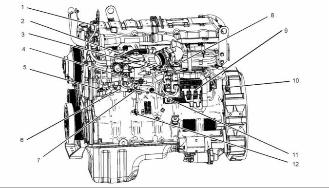
g02974017 |
|
Illustration 6 |
|
Typical example |
|
(1) Valve for the NOx Reduction System (NRS) (2) Inlet air temperature sensor (3) Inlet manifold air pressure sensor (4) Water in fuel sensor |
|
(5) Engine oil temperature sensor (6) Injection pressure regulator (7) Engine fuel pressure sensor (8) Air inlet heater |
|
(10) Crankshaft position sensor (11) Coolant jacket heater (12) Engine oil pressure sensor |
|
(9) Control module |
|
This document is printed from SPI². Not for RESALE |
![]()
![]()
|
14 |
|
KENR8772 |
|
Systems Operation Section |
|
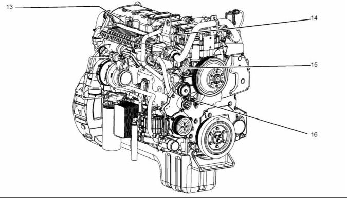
g02976178 |
|
Illustration 7 |
|
Typical example |
|
(13) Injection control pressure sensor (internal) |
|
(14) Exhaust back pressure sensor (15) Engine coolant temperature sensor |
|
(16) Camshaft position sensor |
|
This document is printed from SPI². Not for RESALE |
![]()
![]()
|
KENR8772 |
|
15 Systems Operation Section |
|
g02732035 |
|
Illustration 8 |
|
Typical example |
|
(1) Valve for the NOx Reduction System (NRS) (2) Inlet air temperature sensor |
|
(3) Inlet manifold air pressure sensor (4) Water in fuel sensor (5) Engine oil temperature sensor |
|
(6) Injection pressure regulator (7) Engine fuel pressure sensor (8) Air inlet heater |