 English
 Espaol
 Franais
 阿拉伯
阿拉伯 中文
中文 Deutsch
 Italiano
 Português
 日本
日本 韩国
韩国 български
 hrvatski
 esky
esky Dansk
Dansk Nederlands
 suomi
suomi Ελληνικ
 印度
印度 norsk
norsk Polski
 Roman
Roman русский
 Svenska
Perkins珀金斯1600柴油发动机7079597 C92缸套供应商,Perkins珀金斯1600柴油发动机7079597 C92缸套技术价格规格咨询服务,Perkins珀金斯1600柴油发动机7079597 C92缸套零配件供应,Perkins珀金斯1600柴油发动机7079597 C92缸套售后服务中心,Perkins珀金斯1600柴油发动机7079597 C92缸套,Perkins珀金斯1600柴油发动机7079597 C92缸套详细的技术参数,

产品中心
Perkins珀金斯1600柴油发动机7079597 C92缸套
详细描述
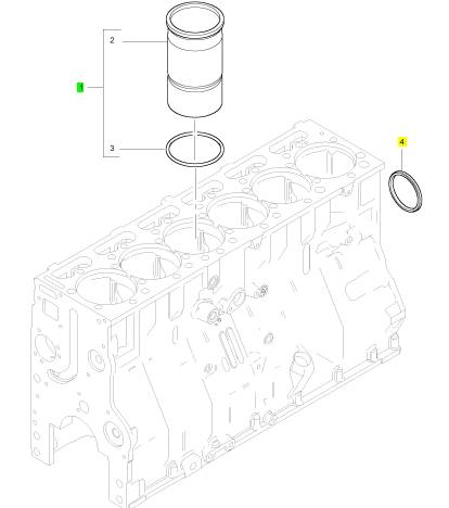
项目 零配件号码 新件号 描述
1 7079597 C92 6 7079597 C92 缸套装备
4 1842730 C3 1 1842730 C3 密封 -凸轮轴
|
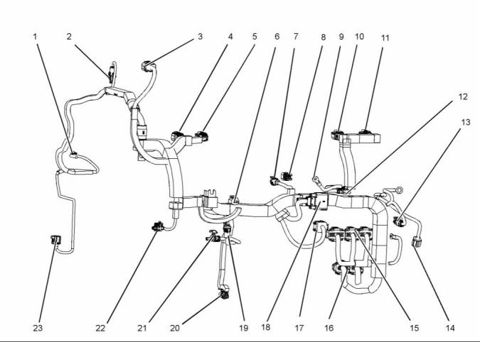
Illustration 13 |
|
(1) Coolant temperature (2) Exhaust back pressure (3) NRS (4) Injection control (5) Injectors 1 and 2 (6) Water in fuel |
|
(9) Inlet heater terminal (10) Injectors 3 and 4 (11) Injectors 5 and 6 (12) Plug for inlet heater (13) Relay (14) Crankshaft position (15) Injector drive connections (16) ECM |
|
(17) NRS drive (18) Customer connection (19) Low-pressure fuel (20) Engine oil pressure (21) Injection pressure regulator (22) Oil temperature |
|
(7) Inlet manifold air pressure (8) Inlet air temperature |
|
(23) Camshaft position connection |
|
ECM |
|
Reference Voltage (VREF) |
|
The Electronic Control Module (ECM) monitors and controls engine performance to ensure maximum performance and adherence to emissions standards. |
|
The ECM supplies a 5 V VREF signal to input sensors in the electronic control system. By comparing the 5 V VREF signal sent to the sensors with the respective returned signals, the ECM determines pressures, positions, and other variables important to engine and vehicle functions. |
|
The ECM performs the following functions: • Provide Reference Voltage (VREF) • Condition input signals |
|
The ECM supplies two independent circuits for VREF: • VREF (A) supplies 5 V to the engine sensors • VREF (B) supplies 5 V to the OEM wiring harness |
|
• Process and stores control strategies • Control actuators |
|
This document is printed from SPI². Not for RESALE |
![]()
![]()
|
20 |
|
KENR8772 |
|
Systems Operation Section |
|
Signal Conditioner |
|
Random Access Memory (RAM) |
|
The signal conditioner in the internal microprocessor converts analog signals to digital signals, squares up sine wave signals, or amplifies low intensity signals to a level that the ECM microprocessor can process. |
|
RAM stores temporary information for current engine conditions. Temporary information in RAM is lost when the ignition switch is turned to OFF or when ECM power is interrupted. RAM information includes the following: |
|
Microprocessor |
|
• Engine temperature • Engine rpm |
|
The ECM microprocessor stores operating instructions (control strategies) and value tables (calibration parameters). The ECM compares stored instructions and values with conditioned input values to determine the correct strategy for all engine operations. |
|
• Accelerator pedal position |
|
Actuator Control |
|
Continuous calculations in the ECM occur at two different levels or speeds: Foreground and Background. |
|
The ECM controls the actuators by applying a low-level signal (low side driver) or a high-level signal (high side driver). When switched on, both drivers complete a ground or power circuit to an actuator. |
|
• Foreground calculations are faster than background calculations and are normally more critical for engine operation. Engine speed control is an example. |
|
Actuators are controlled in one of the following ways, depending upon type of actuator: |
|
• Duty cycle (percent time on/off) • Switched on or off |
|
• Background calculations are normally variables that change at slower rates. Engine temperature is an example. |
|
• CAN messages |
|
Diagnostic Trouble Codes (DTCs) are set by the microprocessor, if inputs or conditions do not comply with expected values. |
|
Actuators |
|
The ECM controls engine operation with the following: • Valve for the NOx Reduction System (NRS) • Intake Air Heater (IAH) relay • Injection timing |
|
Diagnostic strategies are also programmed into the ECM. Some strategies monitor inputs continuously and command the necessary outputs for correct performance of the engine. |
|
Microprocessor Memory |
|
The ECM microprocessor includes Read Only Memory (ROM) and Random Access Memory (RAM). |
|
• Injection pressure regulation valve |
|
Valve for the NOx Reduction System (NRS) (if equipped) |
|
Read Only Memory (ROM) |
|
ROM stores permanent information for calibration tables and operating strategies. Permanently stored information cannot be changed or lost by turning the ignition switch OFF or when ECM power is interrupted. ROM includes the following: |
|
The valve for the NOx Reduction System (NRS) controls the flow of exhaust gases to the intake manifold. |
|
The valve for the NOx Reduction System (NRS) receives the desired valve position from the ECM for the reduction of NOx. The valve for the NOx Reduction System (NRS) provides feedback to the ECM on the valve position. |
|
• Application configuration, modes of operation, and options |
|
• Engine Family Rating Code (EFRC) • Engine warning and protection modes |
|
The valve for the NOx Reduction System (NRS) constantly monitors the valve position. When an NOx control error is detected, the valve for the NOx Reduction System (NRS) sends a message to the ECM and a DTC is set. |
|
This document is printed from SPI². Not for RESALE |
![]()
|
KENR8772 |
|
21 Systems Operation Section |
|
Intake Air Heater (IAH) Relay |
|
The Intake Air Heater (IAH) system warms the incoming air supply prior to cranking to aid cold engine starting. |
|
The ECM is programmed to energize the IAH elements through the IAH relay while monitoring certain programmed conditions for engine coolant temperature, engine oil temperature, and atmospheric pressure. |
|
The ECM activates the IAH relay. The relay delivers VBAT to the heater elements for a set time, depending on engine coolant temperature and altitude. The ground circuit is supplied directly from the battery ground at all times. |
|
Engine Sensors |
|
Thermistor Sensors |
|
A thermistor sensor varies electrical resistance with changes in temperature. Resistance in the thermistor decreases as temperature increases, and increases as temperature decreases. Thermistors have a resistor that limits current in the ECM to a voltage signal matched with a temperature value. |
|
The top half of the voltage divider is the current limiting resistor inside the ECM. A thermistor sensor has two electrical connectors, signal return and ground. The output of a thermistor sensor is a nonlinear analog signal. |
|
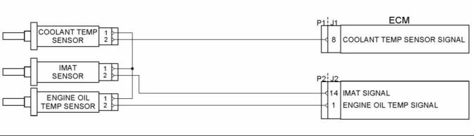
Thermistor type sensors include the following: • Engine Coolant Temperature (ECT) sensor • Engine Oil Temperature (EOT) sensor • Inlet Air Temperature (IAT) sensor |
|
• Manifold Air Temperature (MAT) sensor |
|
g02730803 |
|
Illustration 14 |
|
A typical example of a schematic for the temperature sensors |
|
This document is printed from SPI². Not for RESALE |
![]()
![]()
|
22 |
|
KENR8772 |
|
Systems Operation Section |
|
Engine Coolant Temperature (ECT) Sensor |
|
• Manifold Air Pressure (MAP) sensor |
|
The ECM monitors the ECT signal and uses this information for the instrument panel temperature gauge, coolant compensation, Engine Warning Protection System (EWPS), and IAH operation. The ECT is a backup, if the EOT is out-of-range. The ECT sensor is installed in the water supply housing, to the right of the flat idler pulley assembly. |
|
Engine Oil Temperature (EOT) Sensor |
|
The ECM monitors the EOT signal and uses this information to control fuel quantity and timing when operating the engine. The EOT signal allows the ECM to compensate for differences in oil viscosity for temperature changes. The EOT sensor is located in the rear of the front cover, to the left of the high-pressure pump assembly. |
|
Inlet Air Temperature (IAT) Sensor |
|
The ECM monitors the IAT signal to control injector timing and fuel rate during cold starts. The ECM also uses the IAT signal to control NOx position. The IAT sensor is installed in the air filter housing. |
|
Manifold Air Temperature (MAT) Sensor |
|
The ECM monitors the MAT signal for operation of the NOx Reduction System (NRS). The MAT sensor is located in the intake manifold, to the right of the MAP sensor. |
|
Variable Capacitance Sensors |
|
Variable capacitance sensors measure pressure. The pressure measured is applied to a ceramic material. The pressure forces the ceramic material closer to a thin metal disk. This action changes the capacitance of the sensor. |
|
The sensor is connected to the ECM by the VREF, signal, and signal ground wires. |
|
The sensor receives the VREF and returns an analog signal voltage to the ECM. The ECM compares the voltage with pre-programmed values to determine pressure. |
|
The operational range of a variable capacitance sensor is linked to the thickness of the ceramic disk. The thicker the ceramic disk the more pressure the sensor can measure. |
|
Variable capacitance sensors include the following: • Engine Fuel Pressure (EFP) sensor • Engine Oil Pressure (EOP) sensor |
|
• Exhaust Back Pressure (EBP) sensor |
|
This document is printed from SPI². Not for RESALE |
![]()
|
KENR8772 |
|
23 Systems Operation Section |
|
g02730805 |
|
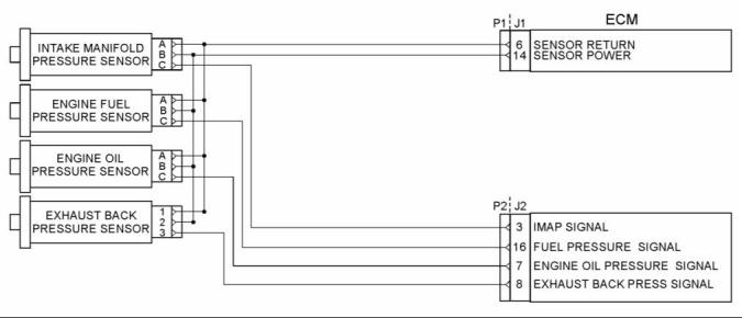
Illustration 15 |
|
A typical example of a schematic for the engine pressure sensors |
|
Engine Fuel Pressure (EFP) Sensor |
|
Magnetic Pickup Sensors |
|
The ECM uses the EFP sensor signal to monitor engine fuel pressure and give an indication when the fuel filter needs to be changed. The EFP sensor is installed in the fuel filter housing on the left side of the crankcase. |
|
A magnetic pickup sensor contains a permanent magnet core that is surrounded by a coil of wire. The sensor generates a voltage signal through the collapse of a magnetic field that is created by a moving metal trigger. The movement of the trigger then creates an AC voltage in the sensor coil. |
|
Engine Oil Pressure (EOP) Sensor |
|
Magnetic pickup sensors used include the following: • Crankshaft Position (CKP) sensor |
|
The ECM monitors the EOP signal, and uses this information for the instrument panel pressure gauge and EWPS. The EOP sensor is installed in the left side of the crankcase, below the left side of the fuel filter housing. |
|
• Camshaft Position (CMP) sensor |
|
Exhaust Back Pressure (EBP) Sensor |
|
The ECM monitors the exhaust pressure so that the ECM can control the turbocharger, NOx Reduction System (NRS), and intake throttle systems. The sensor provides feedback to the ECM for closed loop control of the turbocharger. The EBP sensor is installed in a bracket mounted on the water supply housing (Freon® compressor bracket). |
|
Manifold Air Pressure (MAP) Sensor |
|
The ECM monitors the MAP signal to determine intake manifold pressure (boost). This information is used to control the turbocharger boost. The MAP sensor is installed in the intake manifold, left of the MAT sensor. |
|
This document is printed from SPI². Not for RESALE |
![]()
![]()
|
24 |
|
KENR8772 |
|
Systems Operation Section |
|
g02730800 |
|
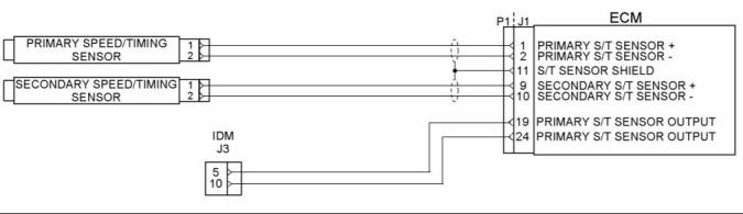
Illustration 16 |
|
A typical example of a schematic for speed/timing sensors |
|
Crankshaft Position (CKP) Sensor |
|
The CKP sensor provides the ECM with a signal that indicates crankshaft speed and position. As the crankshaft turns, the CKP sensor detects a 60 tooth timing disk on the crankshaft. Teeth 59 and 60 are missing. By comparing the CKP signal with the CMP signal, the ECM calculates engine rpm and timing requirements. The CKP sensor is installed in the top left side of the flywheel housing. |
|
Camshaft Position (CMP) Sensor |
|
The CMP sensor provides the ECM with a signal that indicates camshaft position. As the cam rotates, the sensor identifies the position of the cam by locating a peg on the cam. The CMP sensor is installed in the front cover, above and to the right of the water pump pulley. |
|
Micro Strain Gauge (MSG) Sensors |
|
A Micro Strain Gauge (MSG) sensor measures pressure. Pressure to be measured exerts force on a pressure vessel that stretches and compresses to change resistance of strain gauges bonded to the surface of the pressure vessel. Internal sensor electronics convert the changes in resistance to a ratiometric voltage output. |
|
The sensor is connected to the ECM by the VREF, signal, and signal ground wires. |
|
The sensor is powered by VREF received from the ECM and is grounded through the ECM to a common sensor ground. The ECM compares the voltage with pre-programmed values to determine pressure. |
|
The micro strain gauge type sensor is the following: • Injection Control Pressure (ICP) |
|
This document is printed from SPI². Not for RESALE |
![]()
![]()
|
KENR8772 |
|
25 Systems Operation Section |
|
g02730804 |
|
Illustration 17 |
|
A typical example of a schematic for injection control pressure sensor |
|
Injection Control Pressure (ICP) |
|
The ECM monitors the ICP signal to determine injection control pressure for engine operation. The ICP signal is used to control the IPR valve. The ICP sensor provides feedback to the ECM for Closed Loop IPR control. The ICP sensor is under the valve cover, forward of the No. 6 fuel injector in the high-pressure oil manifold. |
|
Switches |
|
Switch sensors indicate position, level, or status. They operate open or closed, regulating the flow of current. A switch sensor can be a voltage input switch or a grounding switch. A voltage input switch supplies the ECM with a voltage when it is closed. A grounding switch grounds the circuit when closed, causing a zero voltage signal. Grounding switches are usually installed in series with a current limiting resistor. |
|
Switches include the following: • Engine Coolant Level (ECL) (if equipped) • Water In Fuel (WIF) |
|
g02730839 |
|
Illustration 18 |
|
A typical example of a schematic for the water in fuel switch |
|
Engine Coolant Level (ECL) (if equipped) |
|
ECL is part of the Engine Warning Protection System (EWPS). The ECL , , , switch is used in plastic deaeration tanks. When a magnetic switch is open, the tank is full. |
|
This document is printed from SPI². Not for RESALE |