 English
 Espaol
 Franais
 阿拉伯
阿拉伯 中文
中文 Deutsch
 Italiano
 Português
 日本
日本 韩国
韩国 български
 hrvatski
 esky
esky Dansk
Dansk Nederlands
 suomi
suomi Ελληνικ
 印度
印度 norsk
norsk Polski
 Roman
Roman русский
 Svenska
Perkins珀金斯1600柴油发动机7092373 C92活塞及缸套供应商,Perkins珀金斯1600柴油发动机7092373 C92活塞及缸套技术价格规格咨询服务,Perkins珀金斯1600柴油发动机7092373 C92活塞及缸套零配件供应,Perkins珀金斯1600柴油发动机7092373 C92活塞及缸套售后服务中心,Perkins珀金斯1600柴油发动机7092373 C92活塞及缸套,Perkins珀金斯1600柴油发动机7092373 C92活塞及缸套详细的技术参数,

产品中心
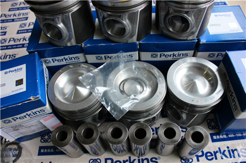
Perkins珀金斯1600柴油发动机7092373 C92活塞及缸套
详细描述
项目 零配件号码 新件号 描述
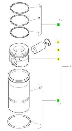
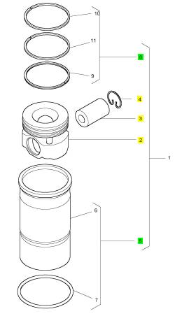
1 7092373 C92 6 7092373 C92 活塞及缸套装备
1 7092373 C91 6 7092373 C92 活塞及缸套装备
1 7092373 C91 6 7092373 C92 活塞及缸套装备
项目 零配件号码 新件号 描述
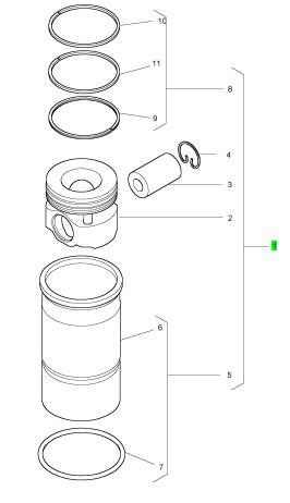
2 7081269 C1 1 7081269 C1 活塞
3 1874000 C1 1 1874000 C1 轴头销
4 1818702 C1 2 1818702 C1 CIRCLIP
5 7079597 C92 1 7079597 C92 缸套装备
8 7092838 C91 1 7092838 C91 活塞环装备
项目 零配件号码 新件号 描述
6 1 缸套 - 压八配合
7 1842115 C1 1 1842115 C1 密封
项目 零配件号码 新件号 描述
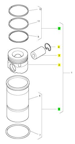
2 7081269 C1 1 7081269 C1 活塞
3 1874000 C1 1 1874000 C1 轴头销
4 1818702 C1 2 1818702 C1 CIRCLIP
5 7079597 C92 1 7079597 C92 缸套装备
8 7092838 C91 1 7092838 C91 活塞环装备
8 1876099 C91 1 7092838 C91 活塞环装备
项目 零配件号码 新件号 描述
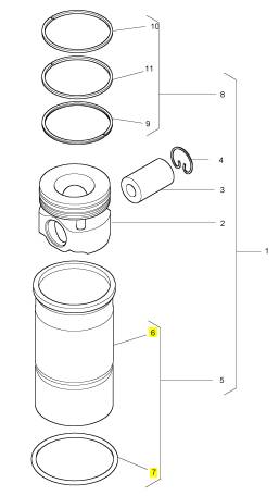
2 7081269 C1 1 7081269 C1 活塞
3 1874000 C1 1 1874000 C1 轴头销
4 1818702 C1 2 1818702 C1 CIRCLIP
5 7079597 C92 1 7079597 C92 缸套装备
8 7092838 C91 1 7092838 C91 活塞环装备
8 1876099 C91 1 7092838 C91 活塞环装备
|
A pulse-width controlled current energizes the open coil. Magnetic force moves the spool valve open. High-pressure oil flows past the spool valve and onto the top of the intensifier piston. Oil pressure overcomes the force of the intensifier piston spring and the intensifier starts to move down. An increase in fuel pressure under the plunger seats the fuel inlet check ball, and fuel pressure starts to build on the needle. |
|
The pulse-width controlled current to the open coil is shut off, but the spool valve remains open. High-pressure oil from high-pressure oil manifold continues to flow past the spool valve. The intensifier piston and plunger continue to move and fuel pressure increases in the barrel. When fuel pressure rises above the VOP, the needle lifts off the seat and injection begins. |
|
End of Injection |
|
When the ECM determines that the correct injector on-time has been reached (the correct amount of fuel has been delivered), the ECM sends a pulse-width controlled current to the close coil of the injector. The current energizes the close coil and magnetic force closes the spool valve. High-pressure oil is stopped against the spool valve. |
|
The pulse-width controlled current to close the coil is shut off, but the spool valve remains closed. Oil above the intensifier piston flows past the spool valve through the exhaust ports. The intensifier piston and plunger return to their initial positions. Fuel pressure decreases until the needle control spring forces the needle back onto the seat. |
|
This document is printed from SPI². Not for RESALE |
![]()
|
34 |
|
KENR8772 |
|
Systems Operation Section |
|
Fuel Supply System |
|
g02729994 |
|
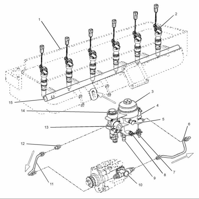
Illustration 26 |
|
Typical example of low-pressure fuel system |
|
(1) Cylinder head (2) Electronic unit injector (3) Fuel filter cap (4) Fuel filter base (5) Diagnostic coupling assembly and dust cap |
|
(6) Transfer pump outlet tube assembly (7) Water drain valve (8) Water In Fuel (WIF) sensor (9) Engine Fuel Pressure (EFP) sensor (10) Low-pressure fuel pump |
|
(12) Fitting assembly with check valve (13) Fuel priming pump (14) Fuel strainer cap |
|
(15) Low-pressure fuel rail |
|
(11) Transfer pump inlet tube assembly |
|
This document is printed from SPI². Not for RESALE |
![]()
![]()
|
KENR8772 |
|
35 Systems Operation Section |
|
g02730792 |
|
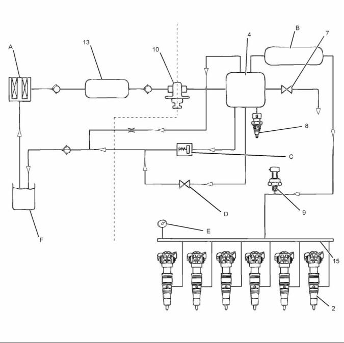
Illustration 27 |
|
Typical example of the fuel supply system flow |
|
(A) Fuel strainer |
|
(F) Fuel tank |
|
(8) Water In Fuel (WIF) sensor |
|
(B) Fuel standpipe (fuel entry high point) (C) Fuel pressure regulator valve (D) Fuel filter service drain to tank valve (E) Diagnostic port |
|
(2) Electronic unit injector (4) Fuel filter base that includes fuel filter and water separator |
|
(9) Engine Fuel Pressure (EFP) sensor (10) Low-pressure fuel pump (13) Fuel priming pump |
|
(7) Water drain valve |
|
(15) Low-pressure fuel rail |
|
The low-pressure fuel pump draws fuel through the fuel lines from the fuel tank. Fuel enters the fuel filter header assembly and passes through the 150 micron strainer. |
|
Fuel flows through the filter element and the standpipe. The filter element removes debris from the fuel. The standpipe prevents fuel from draining from the fuel rail during service. |
|
Fuel flows from the strainer through the low-pressure fuel pump to the fuel filter for further conditioning. |
|
If water is in the fuel, the fuel filter element repels the water. The water is collected at the bottom of the main filter element cavity in the fuel filter assembly. |
|
This document is printed from SPI². Not for RESALE |
![]()
![]()
|
36 |
|
KENR8772 |
|
Systems Operation Section |
|
When the maximum amount of water is collected in the element cavity, the Water In Fuel (WIF) sensor sends a signal to the Engine Control Module (ECM). |
|
A water drain valve is located on the fuel filter assembly and can be opened to drain contaminants (usually water) from the assembly. |
|
A fuel pressure regulator valve is built into the fuel filter header assembly. The regulator valve is calibrated to open at 455 ± 34 kPa (66 ± 5 psi) to regulate and relieve excessive fuel pressure. Excess fuel is sent through a fuel return line back to the fuel tank. Return fuel is not filtered. |
|
Fuel continuously flows from the top of the filter element cavity, through a 0.2 mm air purge orifice (filter center tube feature), and into the return fuel line. This aids in removing trapped air from the element cavity as a result of servicing. |
|
When the fuel filter is removed, an automatic drain-to-tank valve is opened. Fuel present in the filter housing then drains out and back to the tank to provide improved cleanliness during servicing. |
|
The Engine Fuel Pressure (EFP) sensor detects low fuel pressure caused by a fuel restriction or dirty fuel filter. The EFP sensor sends a signal to the ECM when pressure is below programmed values for various engine conditions. |
|
Filtered fuel flows from the fuel filter header assembly into the fuel rail. The fuel rail is an integral part of the intake manifold. The fuel flows into six cylinder head passages to each fuel injector. |
|
When the fuel injectors are activated, fuel flows from the fuel passages through the injector inlet ports and inside the fuel injectors. |
|
This document is printed from SPI². Not for RESALE |
![]()
|
KENR8772 |
|
37 Systems Operation Section |
|
i04031072 |
|
Air Inlet and Exhaust System |
|
g02729092 |
|
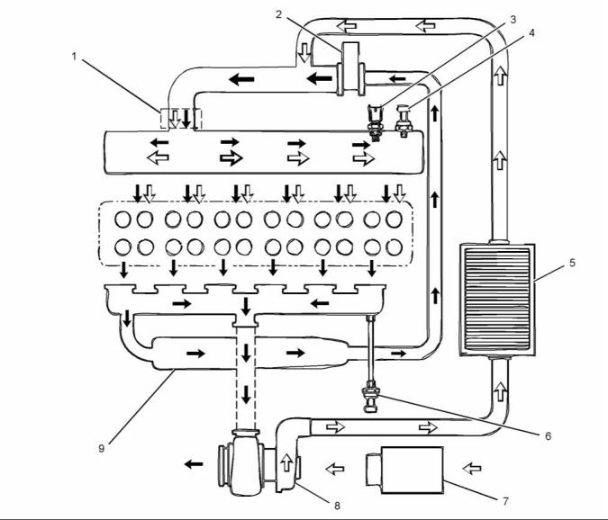
Illustration 28 |
|
Typical example |
|
(1) Inlet Air Heater Control (IAHC) (2) Valve for the NOx Reduction System (NRS) (if equipped) |
|
(4) Inlet manifold air pressure sensor |
|
(8) Turbocharger (9) Exhaust gas cooler (NRS) (if equipped) |
|
(5) Charge Air Cooler (CAC) (6) Exhaust back pressure sensor (7) Air filter assembly |
|
(3) Inlet air temperature sensor |
|
Note: The white arrows show the flow of inlet air. The black arrows show the flow of exhaust gases. |
|
• Turbocharger |
|
• Charge Air Cooler (CAC) • Intake throttle valve |
|
The engine components of the air inlet and exhaust system control the quality of air and the amount of air that is available for combustion. The components of the air inlet and exhaust system are the following components: |
|
• NOx Reduction System (NRS) (if equipped) • Inlet manifold |
|
• Air cleaner |
|
This document is printed from SPI². Not for RESALE |
![]()
![]()
|
38 |
|
KENR8772 |
|
Systems Operation Section |
|
• Inlet Air Heater Control (IAHC) • Valves and valve system components • Piston and cylinder |
|
• Exhaust manifold |
|
Air flows through the air filter assembly and enters the turbocharger. The turbocharger compressor increases the pressure, temperature, and density of the intake air before the air enters the Charge Air Cooler (CAC). Cooled compressed air flows from the CAC into the inlet manifold and duct of the control valve for the exhaust gas valve. |
|
If the control valve for the exhaust gas valve is open, exhaust gas will pass through the NOx Reduction System (NRS) and mix with the filtered intake air. This mixture flows through the inlet air heater and into the inlet manifold. |
|
If the control valve for the exhaust gas valve is closed, only filtered intake air will flow through the inlet air heater and into the inlet manifold. |
|
After combustion gases exit through the exhaust valves and ports, the gas is forced through the exhaust manifold to the NRS and turbocharger. |
|
Some gas flows through the NRS system, which is controlled by the exhaust gas valve. The remaining gas flows to the turbocharger turbine. |
|
The compressor wheel is connected to the turbine wheel by a shaft. The turbocharger compressor wheel compresses the filtered air. |
|
Exhaust gases exit the turbocharger and are released from the exhaust system. |
|
Charge Air Cooler (CAC) |
|
The Charge Air Cooler (CAC) is mounted on top of the radiator. Air from the turbocharger passes through a network of heat exchanger tubes before entering the engine intake system. Outside air flowing over the heat exchanger tube fins cools the charge air. Cooling the charge air increases the density and improves the air to fuel ratio during combustion. |
|
This document is printed from SPI². Not for RESALE |
![]()
|
KENR8772 |
|
39 Systems Operation Section |
|
NOx Reduction System (NRS) (If equipped) |
|
g02730874 |
|
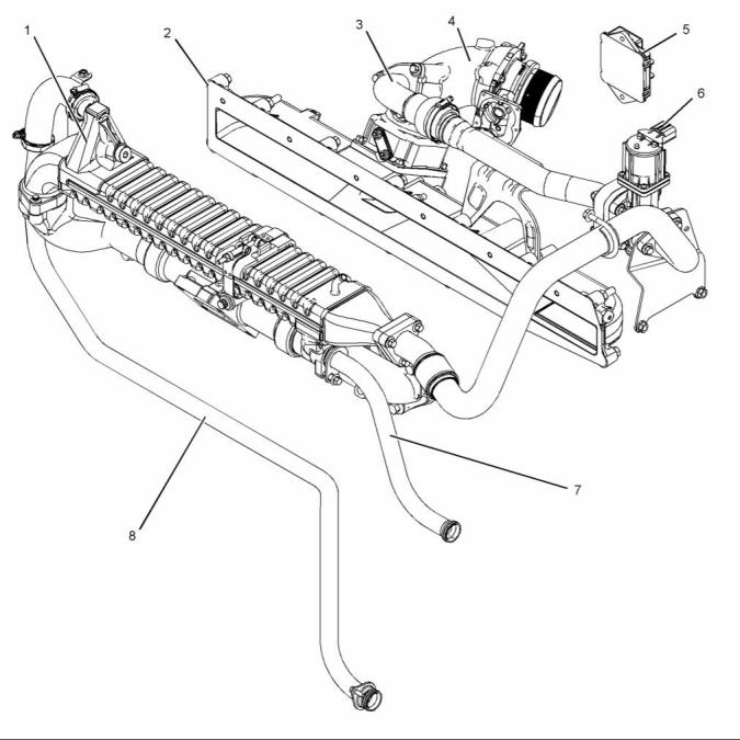
Illustration 29 |
|
Typical example |
|
(1) Exhaust gas cooler (NRS) (2) Inlet manifold (3) Metering tube |
|
(5) Valve drive module (6) Valve for the NOx Reduction System (NRS) |
|
(8) Coolant supply tube |
|
(4) Exhaust gas valve (NRS) |
|
(7) Coolant return tube |
|
The NOx Reduction System (NRS) reduces Nitrogen Oxide (NOx) engine emissions. NOx forms during a reaction between nitrogen and oxygen at high temperatures during combustion. Combustion starts when fuel is injected into the compressed combustion chamber. |
|
Metered exhaust gas from the exhaust manifold flows into the exhaust gas cooler. Cooled exhaust gas flows through the exhaust tube assembly to the exhaust gas control valve. |
|
This document is printed from SPI². Not for RESALE |
![]()
![]()
|
40 |
|
KENR8772 |
|
Systems Operation Section |
|
When a reduction in NOx is required, the exhaust gas control valve opens and allows cooled exhaust gas to enter. This exhaust gas is directed into the exhaust gas valve duct where the exhaust gas is mixed with filtered inlet air. |
|
Turbocharger |
|
Exhaust Gas Control Valve (If equipped) |
|
The exhaust gas control valve consists of three major components, a valve, an actuator motor, and an Integrated Circuit (IC). |
|
The exhaust gas control valve is installed in the exhaust gas valve manifold on the top front of the engine. |
|
The exhaust gas valve uses a DC motor to control position of the valve assembly. The motor pushes directly on the valve stem to open. The valve is shut by a spring. The valve assembly has two poppet valves on a common shaft. |
|
The Integrated Circuit (IC) has three hall effect position sensors to monitor valve movement. |
|
g00302786 |
|
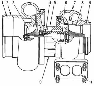
Illustration 30 |
|
Typical example of a cross section of a turbocharger |
|
(1) Air intake |
|
NOx Reduction System Closed Loop System (If equipped) |
|
(2) Compressor housing (3) Compressor wheel (4) Bearing |
|
(5) Oil inlet port (6) Bearing |
|
The ECM commands the exhaust gas control valve position based on engine speed and load conditions. The exhaust gas control valve provides feedback to the ECM on current valve position. |
|
(7) Turbine housing (8) Turbine wheel (9) Exhaust outlet (10) Oil outlet port (11) Exhaust inlet |
|
The turbocharger is mounted on the outlet of the exhaust manifold. The exhaust gas from the exhaust manifold enters the exhaust inlet (11) and passes through the turbine housing (7) of the turbocharger. Energy from the exhaust gas causes the turbine wheel (8) to rotate. The turbine wheel is connected by a shaft to the compressor wheel (3). |
|
As the turbine wheel rotates, the compressor wheel is rotated. The rotation of the compressor wheel causes the intake air to be pressurized through the compressor housing (2) of the turbocharger. |
|
When the load on the engine increases, more fuel is injected into the cylinders. The combustion of this additional fuel produces more exhaust gases. The additional exhaust gases cause the turbine and the compressor wheels of the turbocharger to turn faster. As the compressor wheel turns faster, air is compressed to a higher pressure and more air is forced into the cylinders. The increased flow of air into the cylinders allows the fuel to be burnt with greater efficiency. This produces more power. |
|
When engine load is light, the flow of exhaust gases decreases which causes reduction in air volume and boost pressure. |
|
This document is printed from SPI². Not for RESALE |
![]()
![]()
|
KENR8772 |
|
41 Systems Operation Section |
|
A wastegate is installed on the turbine housing of the turbocharger. The wastegate is a valve that allows exhaust gas to bypass the turbine wh, eel of the turbocharger. The operation of the wastegate is dependent on the pressurized air (boost pressure) from the turbocharger compressor. |
|
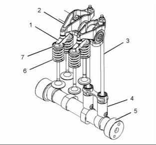
The valve system components control the flow of inlet air into the cylinders during engine operation. The valve system components also control the flow of exhaust gases out of the cylinders during engine operation. |
|
The crankshaft gear drives the camshaft gear through an idler gear. The camshaft (5) must be timed to the crankshaft in order to get the correct relation between the piston movement and the valve movement. |
|
The shaft that connects the turbine to the compressor wheel rotates in bearings (4) and (6). The bearings require oil under pressure for lubrication and cooling. The oil that flows to the lubricating oil inlet port (5) passes through the center of the turbocharger which retains the bearings. The oil exits the turbocharger from the lubricating oil outlet port (10) and returns to the oil pan. |
|
The camshaft (5) has two camshaft lobes for each cylinder. The lobes operate either a pair of inlet valves or a pair of exhaust valves. As the camshaft turns, lobes on the camshaft cause the lifter (4) to move the pushrod (3) up and down. Upward movement of the pushrod (3) against the rocker arm (2) results in a downward movement that acts on the valve bridge (1). This action opens a pair of valves (7) which compresses the valve springs (6). When the camshaft has rotated to the peak of the lobe, the valves are fully open. |
|
Crankcase Breather |
|
NOTICE |
|
The crankcase breather gases are part of the engines measured emissions output. Any tampering with the breather system could invalidate the engines emis- sions compliance. |
|
When the camshaft (5) rotates further, the two valve springs (6) under compression start to expand. The valve stems are under tension of the springs. The stems are pushed upward in order to maintain contact with the valve bridge (1). The continued rotation of the camshaft (5) causes the rocker arm (2), the pushrods (3) and the lifters (4) to move downward until the lifter reaches the bottom of the lobe. The valves are now closed. The cycle is repeated for all the valves on each cylinder. |
|
A open crankcase breather system uses an engine mounted oil separator to return oil to the crankcase and vent crankcase pressure into the intake system. |
|
The open crankcase ventilation system separates oil from crankcase gases and returns oil to the oil pan. |
|
A turbine in the breather housing assembly is driven by engine oil pressure. |
|
i04031012 |
|
Valve System Components |
|
Lubrication System |
|
g02440436 |
|
Illustration 31 |
|
Typical example |
|
This document is printed from SPI². Not for RESALE |
![]()
![]()
![]()
![]()
|
42 |
|
KENR8772 |
|
Systems Operation Section |
|
g02729107 |
|
Illustration 32 |
|
Typical example |
|
(1) Valve mechanism cover (2) Rocker shaft assembly (3) Reservoir for unit injector hydraulic pump (4) Unfiltered oil gallery (5) Housing (front) (6) Oil pump (7) Crankcase breather (8) Suction pipe |
|
(9) Turbocharger (10) Oil cooler (11) Oil filter (12) Oil filter base (13) Oil pressure regulator relief valve (14) Regulator relief valve drain (15) Oil pan |
|
(17) Piston cooling jet (18) Main filtered oil gallery (19) Camshaft (20) Cylinder block (21) Vertical gallery (22) Cylinder head |
|
(16) Crankshaft |
|
This document is printed from SPI². Not for RESALE |