 English
 Espaol
 Franais
 阿拉伯
阿拉伯 中文
中文 Deutsch
 Italiano
 Português
 日本
日本 韩国
韩国 български
 hrvatski
 esky
esky Dansk
Dansk Nederlands
 suomi
suomi Ελληνικ
 印度
印度 norsk
norsk Polski
 Roman
Roman русский
 Svenska
Perkins珀金斯1600柴油发动机1873938 C98燃油过滤器供应商,Perkins珀金斯1600柴油发动机1873938 C98燃油过滤器技术价格规格咨询服务,Perkins珀金斯1600柴油发动机1873938 C98燃油过滤器零配件供应,Perkins珀金斯1600柴油发动机1873938 C98燃油过滤器售后服务中心,Perkins珀金斯1600柴油发动机1873938 C98燃油过滤器,Perkins珀金斯1600柴油发动机1873938 C98燃油过滤器详细的技术参数,

产品中心
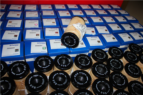
Perkins珀金斯1600柴油发动机1873938 C98燃油过滤器
详细描述
项目 零配件号码 新件号 描述
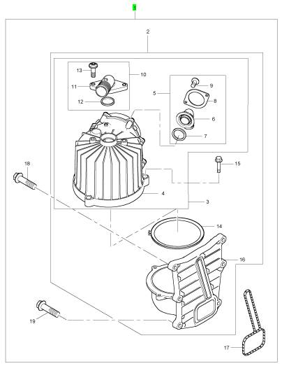
1 1873938 C98 1 1873938 C98 燃油过滤器
1 1873938 C97 1 1873938 C97 燃油过滤器
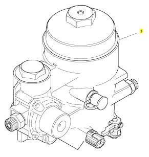
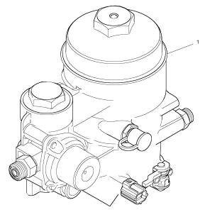
项目 零配件号码 新件号 描述
2 1 燃油过滤器壳
3 1872957 C91 1 1872957 C91 水温度感应传感器
4 1873923 C92 1 1873923 C92 排泄栓塞
5 1891658 C91 1 1891658 C91 帽
6 1878042 C92 1 1878042 C92 燃油过滤器
7 1873910 C92 1 1873910 C92 过滤器组合
8 1873906 C1 1 1873906 C1 密封垫片 - 燃油的过滤器
9 1839415 C91 1 1839415 C91 油压感应传感器
10 1875228 C1 1 1875228 C1 密封垫片 - 燃油的过滤器
11 1831387 C1 1 1831387 C1 螺旋
12 1839032 C91 1 1839032 C91 联结器
13 1841487 C91 1 1841487 C91 承接器
14 1655349 C1 1 1655349 C1 帽
15 1872550 C91 1 1872550 C91 停机电磁阀
16 1886152 C91 1 1886152 C91 压力阀
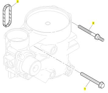
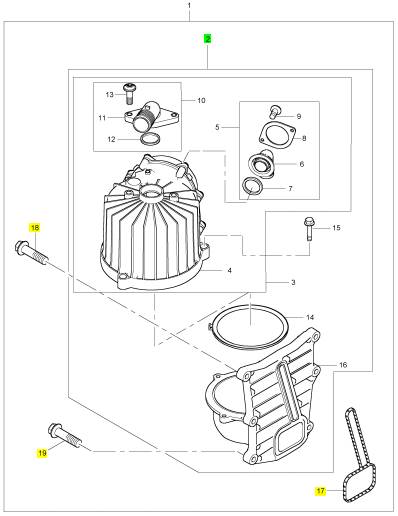
项目 零配件号码 新件号 描述
1 1881564 C1 1 1881564 C1 螺拴
2 1832336 C1 3 1832336 C1 螺拴
3 1873906 C1 1 1873906 C1 密封垫片 - 燃油的过滤器
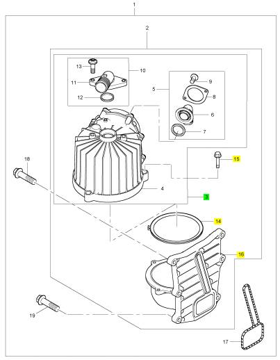
项目 零配件号码 新件号 描述
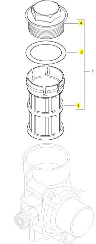
1 1873910 C92 1 1873910 C92 过滤器组合
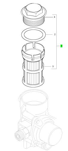
项目 零配件号码 新件号 描述
2 1873909 C2 1 1873909 C2 密封O型圈
3 1 过滤器
4 1 盖
项目 零配件号码 新件号 描述
1 1839415 C91 1 1839415 C91 油压感应传感器
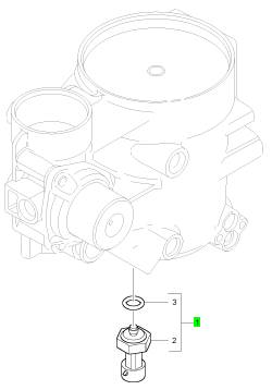
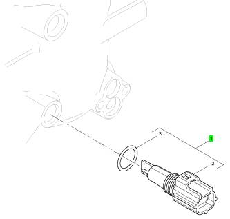
项目 零配件号码 新件号 描述
1 1872957 C91 1 1872957 C91 水温度感应传感器
项目 零配件号码 新件号 描述
1 7093618 C92 1 7093618 C92 呼吸者
1 1891453 C94 1 1891453 C94 呼吸者
项目 零配件号码 新件号 描述
2 1 呼吸者座
17 1880984 C3 1 1880984 C3 密封
18 1818957 C1 3 1818957 C1 螺拴
19 1818958 C1 3 1818958 C1 螺拴
项目 零配件号码 新件号 描述
3 1 呼吸者
14 1875880 C2 1 1875880 C2 密封
15 31048 R1 3 31048 R1 螺拴
16 1 呼吸者
项目 零配件号码 新件号 描述
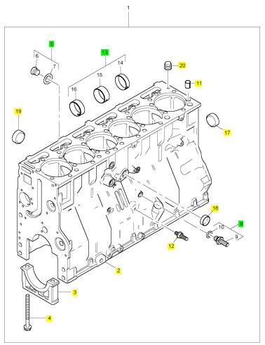
1 1882391 C92 1 1882391 C92 曲轴箱
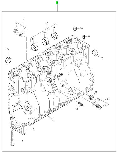
项目 零配件号码 新件号 描述
2 1 曲轴箱
3 7 要点轴承盖
4 1883597 C1 14 1883597 C1 螺旋
5 1837644 C91 1 1837644 C91 栓塞装备
8 1847663 C91 1 1847663 C91 连接装备
11 1833125 C1 2 1833125 C1 合钉
12 1838845 C1 1 1838845 C1 栓塞
13 1879791 C92 1 1879791 C92 凸轮轴衬套
17 40005 R1 1 40005 R1 栓塞
18 23623 R1 1 23623 R1 栓塞
19 23624 R1 1 23624 R1 栓塞
20 1833469 C1 2 1833469 C1 栓塞
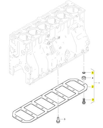
项目 零配件号码 新件号 描述
2 1 梯框
3 1822096 C1 14 1822096 C1 螺拴
4 1842546 C1 14 1842546 C1 间隔器
5 1842547 C1 14 1842547 C1 承件
|
Testing and Adjusting Section |
|
Note: The fuel test valve is located on the front of the fuel filter base. |
|
2. Insert the other end of the clear test line of Tooling |
|
(A) into a suitable container. |
|
Fuel System |
|
3. Crank the engine for 20 seconds. Open the shut-off valve to check for air in fuel. |
|
i04112210 |
|
4. Run engine at low idle. Open the shut-off valve |
|
Fuel System - Inspect |
|
to check for air in fuel. |
|
5. Run engine at high idle. Open the shut-off valve to check for air in fuel. |
|
A problem with the components that send fuel to the engine can cause low fuel pressure. This can decrease engine performance. |
|
6. If there is no air in fuel, no repair is required. If there is air in fuel, proceed to “Alternative Fuel Supply to Fuel Filter Base”. |
|
1. Check the fuel level in the fuel tank. Ensure that the vent in the fuel cap is not filled with dirt. |
|
Alternative Fuel Supply to Fuel Filter Base |
|
2. Check all fuel lines for fuel leakage. The fuel lines must be free from restrictions and faulty bends. Verify that the fuel return line is not collapsed. |
|
1. Disconnect the supply line from the fuel filter base. |
|
2. Fabricate a fuel test line. Use a male 90 degree fuel line connection and install a clear plastic line long enough to reach an alternative fuel source. |
|
3. Install a new fuel filter. |
|
4. Cut the old filter open with a suitable filter cutter. Inspect the filter for excess contamination. Determine the source of the contamination. Make the necessary repairs. |
|
3. Connect the test fuel line between the fuel filter base inlet and alternative fuel source. |
|
4. Prime the fuel system. Refer to Systems Operation Testing and Adjusting, “Fuel System - Prime” for the correct procedure. |
|
5. Service the primary fuel filter (if equipped). |
|
6. Operate the hand priming pump (if equipped). If excessive resistance is felt, inspect the fuel pressure regulating valve. If uneven resistance is felt, test for air in the fuel. Refer to Systems Operation, Testing and Adjusting, “Air in Fuel - Test” for more information. |
|
5. Crank the engine for a maximum 20 seconds. Open the shut-off valve to check for aeration. |
|
6. If there is no air in fuel, repair the restriction or leak between the fuel filter base and the fuel tank. If there is air in fuel, proceed to “Alternative Fuel to Fuel Pump Test”. |
|
7. Remove any air that may be in the fuel system. Refer to Systems Operation, Testing and Adjusting, “Fuel System - Prime”. |
|
Alternative Fuel to Fuel Pump Test |
|
i04876619 |
|
1. Remove fuel pump supply line. |
|
Air in Fuel - Test |
|
2. Fabricate a test fuel line. Use spare fuel line. Ensure that sleeve seals are in good shape. Cut the line in half. Use test fuel line section that supplies the fuel pump. Install clear plastic line in place of removed section. Secure plastic line with a clamp. |
|
Table 1 |
|
Required Tools |
|
Tool A |
|
Part Number 27610379 27610386 |
|
Part Description Fuel Pressure Gauge Fuel Test Coupler |
|
Qty 1 |
|
3. Connect the test fuel line between the fuel pump inlet and an alternative fuel source. |
|
B |
|
1 |
|
4. Prime the fuel system. Refer to Systems Operation Testing and Adjusting, “Fuel System - Prime” for the correct procedure. |
|
1. Connect Tooling (A) and (B) to the fuel test valve. |
|
This document is printed from SPI². Not for RESALE |
![]()
|
KENR8772 |
|
53 Testing and Adjusting Section |
|
5. Crank engine for maximum of 20 seconds. Check for signs of aeration in the clear test line. |
|
6. If there is air in fuel, remove the test set-up from the fuel pump inlet. Repair or replace the fuel filter base. Test for air in fuel at the inlet manifold test valve. If there is no air in fuel, proceed to “Combustion Leaks to Fuel Test” |
|
Combustion Leaks to Fuel Test |
|
1. Remove the valve mechanism cover. Refer to Disassembly and Assembly for the correct procedure. |
|
2. Check that all the bolts that secure the clamps for the electronic unit injectors are tightened to the correct torque. |
|
3. Remove all the electronic unit injectors. Refer to Disassembly and Assembly for the correct procedure. Replace injector O-rings and combustion washers. Install the electronic unit injectors. Refer to Disassembly and Assembly for the correct procedure. |
|
g02316083 |
|
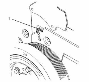
Illustration 45 |
|
Typical example |
|
3. Position piston No. 1 at the top center position on the compression stroke. Observe cylinder 6 rocker arms in overlap as the vibration damper timing mark approaches the TDC mark (1) on the front cover. Refer to illustration 45. Cylinder 6 exhaust valve will be closing (coming up) and the inlet valve will be starting to open (going down). |
|
Note: An electronic unit injector with carbon build-up typically indicates a loose electronic unit injector. |
|
4. Repeat steps 1 to 6 to check for air in fuel. |
|
i04112554 Finding Top Center Position for No. 1 Piston |
|
Note: If the vibration damper is removed, ensure that the vibration damper is correctly installed. Refer to Disassembly and Assembly for the correct procedure. |
|
i04112215 |
|
Fuel Quality - Test |
|
1. Remove the valve mechanism cover. Refer to Disassembly and Assembly, “Valve Mechanism Cover - Remove and Install” for the correct procedure. |
|
Ensure that all adjustments and repairs are performed by authorized personnel that have had the correct training. |
|
2. Turn the crankshaft in the normal direction of engine rotation to remove backlash. |
|
Use the following procedure to test for problems regarding fuel quality: |
|
1. Determine if water and/or contaminants are present in the fuel. Check the water separator (if equipped). If a water separator is not present, proceed to Step 2. Drain the water separator, if necessary. A full fuel tank minimizes the potential for overnight condensation. |
|
Note: A water separator can appear to be full of fuel when the water separator is actually full of water. |
|
This document is printed from SPI². Not for RESALE |
![]()
![]()
|
54 |
|
KENR8772 |
|
Testing and Adjusting Section |
|
2. Determine if contaminants are present in the fuel. Remove a sample of fuel from the bottom of the fuel tank. Visually inspect the fuel sample for contaminants. The color of the fuel is not necessarily an indication of fuel quality. However, fuel that is black, brown, or similar to sludge can be an indication of the growth of bacteria or oil contamination. In cold temperatures, cloudy fuel indicates that the fuel may not be suitable for operating conditions. |
|
• The fuel tank is empty or the fuel tank has been partially drained. |
|
• The low-pressure fuel lines are disconnected. • A leak exists in the low-pressure fuel system. • The fuel filter has been replaced. |
|
If you inspect the engine in operation, always use the proper inspection procedure in order to avoid a fluid penetration hazard. Refer to Operation and Maintenance Manual, “General hazard Information”. |
|
Refer to Operation and Maintenance Manual, “Fluid Recommendations” for more information. |
|
3. If fuel quality is still suspected as a possible cause to problems regarding engine performance, disconnect the fuel inlet line. Temporarily operate the engine from a separate source of fuel that is known to be good. This will determine if the problem is caused by fuel quality. If fuel quality is determined to be the problem, drain the fuel system and replace the fuel filters. Engine performance can be affected by the following characteristics: |
|
• Cetane number of the fuel • Air in the fuel |
|
• Other fuel characteristics |
|
i04198691 |
|
Fuel System - Prime |
|
NOTICE |
|
Care must be taken to ensure that fluids are contained during performance of inspection, maintenance, test- ing, adjusting, and repair of the product. Be prepared to collect the fluid with suitable containers before opening any compartment or disassembling any com- ponent containing fluids. |
|
g02837626 |
|
Illustration 46 |
|
Typical example |
|
Priming with leak off Tool |
|
Dispose of all fluids according to local regulations and |
|
mandates. |
|
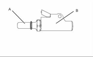
In order to purge air from the fuel system a tool is required. Use a PCL Air Technology Single Clip on Connector CO2H03 or similar. Install a suitable length of clear hose onto connector (A). |
|
NOTICE |
|
Do not crank the engine continuously for more than 30 seconds. Allow the starting motor to cool for two minutes before cranking the engine again. |
|
Ensure that all adjustments and repairs are performed by authorized personnel that have had the correct training. |
|
If air enters the fuel system, the air must be purged from the fuel system before the engine can be started. Air can enter the fuel system when the following events occur: This document is printed from SPI². Not for RESALE |
![]()
![]()
![]()
![]()
![]()
![]()
|
KENR8772 |
|
55 Testing and Adjusting Section |
|
2. Insert the other end of the clear test line of Tooling (A) into a suitable container if necessary. |
|
3. Crank the engine for 20 seconds. Measure the fuel pressure with shut-off valve closed. The minimum fuel pressure should be 138 kPa (20 psi). |
|
4. Run engine at low idle. Measure fuel pressure with shut-off valve closed. The fuel pressure should be between 275 to 515 kPa (40 to 75 psi). |
|
5. Run engine at high idle. Measure fuel pressure with shut-off valve closed. The fuel pressure should be between 275 to 515 kPa (40 to 75 psi). |
|
g02948436 |
|
Illustration 47 |
|
6. If fuel pressure is in specification, no repair is required. If the fuel pressure is below specification, proceed to “Fuel Filter Base Pressure Test”. |
|
Typical example |
|
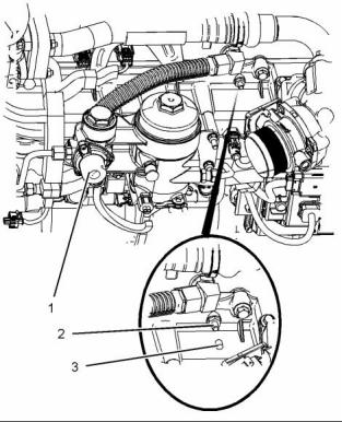
1. Remove the dust cap (3) and install tool (B) onto schrader valve (2). Put the clear hose into a suitable container. |
|
Fuel Filter Base Pressure Test |
|
1. Connect Tooling (A) and (B) to the fuel test valve. |
|
2. Depress the priming pump (1) in order to release |
|
the air from the system. |
|
Note: The fuel test valve is located on the front of the fuel filter base. |
| ,
3. When fuel free from air comes from the schrader valve, stop depressing the priming pump. Remove the tool and install the dust cap. |
|
2. Crank engine for 20 seconds. Measure fuel pressure with shut-off valve closed. The minimum fuel pressure should be 138 kPa (20 psi). |
|
4. Depress the priming pump for a short time in order to pressurize the system. Check the low-pressure system for leaks. |
|
3. If fuel pressure is in specification, replace the secondary filter and clean the primary filter. Refer to Operation and Maintenance Manual for the correct procedures. If fuel pressure is below specification, proceed to “Fuel Inlet Restriction Test”. |
|
5. Priming the fuel filter from empty should take approximately 3 minutes. The time will be dependent on the location of the fuel tank. |
|
6. Remove any container and clean any split fuel from the engine. The system is now primed and the engine ready to start. Operate the starting motor and start the engine. |
|
Fuel Inlet Restriction Test |
|
1. Check for fuel inlet restriction from the primary filter that is located in the fuel filter base. |
|
i04208674 |
|
2. Remove the cap from the filter base. |
|
Fuel System Pressure - Test |
|
3. Connect Tooling (C) and test line to filter base. |
|
4. Route test line from engine compartment to the |
|
operators enclosure of the application. |
|
Table 2 |
|
Required Tools |
|
5. Connect a suitable vacuum gauge to the test line. |
|
Tool A |
|
Part Number 27610379 27610386 |
|
Part Description Fuel Pressure Gauge Fuel Test Coupler |
|
Qty 1 |
|
Note: The vacuum gauge should be capable of measuring up to 101.6 kPa (14.7 psi). |
|
B |
|
1 |
|
6. Measure the high-idle fuel inlet restriction. The maximum pressure should be 20 kPa (3 psi). |
|
Fuel Inlet Restriction Adapter |
|
C |
|
27610392 |
|
1 |
|
7. If fuel inlet restriction is in specification, proceed to “Fuel Pump Operation Test”. If fuel inlet restriction is out of specification, proceed to “Alternate Fuel Supply to Fuel Filter Base Test”. |
|
1. Connect Tooling (A) to the fuel test valve. |
|
Note: The fuel test valve is located on the front of the fuel filter base. |
|
This document is printed from SPI². Not for RESALE |
![]()
![]()
|
56 |
|
KENR8772 |
|
Testing and Adjusting Section |
|
Fuel Pump Operation Test |
|
1. Connect Tooling (A) to fuel test valve in the inlet manifold. |
|
2. Open the shut-off valve. |
|
Note: A closed shut-off valve during the test will yield incorrect values. |
|
3. Disconnect fuel pump supply line from the fuel filter base. |
|
4. Connect test hose to fuel supply and secure with clamp. A cone adapter (included with vacuum pump kit) may also be used. The adapter fits on the end of the fuel supply line. |
|
5. Insert vacuum pump nozzle into the fuel supply line. Ensure the integrity of the seal during the test. |
|
6. Crank the engine for a maximum of 20 seconds. |
|
g03063996 |
|
Illustration 48 |
|
Typical example |
|
7. If vacuum reading is greater than 41 kPa (12 inch mercury), the pump is operating correctly. Proceed to “Alternate Fuel Supply to Fuel Filter Base Test”. |
|
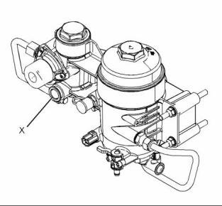
3. Connect the test fuel line at the fuel filter base inlet at position (X) and an alternative fuel source. |
|
4. Connect Tooling (A) to the inlet manifold fuel test valve. |
|
8. If vacuum reading is less than 41 kPa (12 inch mercury), replace the fuel pump. Refer to Disassembly and Assembly for the correct procedure. Repeat steps 3 to 6 to test fuel pressure again at inlet manifold test valve. |
|
5. Crank the engine for a maximum 20 seconds. |
|
6. Measure fuel pressure with the shut-off valve closed. The pressure should be between 275 to 515 kPa (40 to 75 psi). |
|
Alternate Fuel Supply to Fuel Filter Base Test |
|
7. If fuel pressure is below specification, replace the fuel filter base. Refer to Disassembly and Assembly for the correct procedure. Repeat steps 3 to 5 to test fuel pressure again at inlet manifold test valve. If fuel pressure is in specification, and there is no air in fuel, repair the restriction or leak between the fuel filter base and the fuel tank. |
|
1. Disconnect the supply line from the fuel filter base. |
|
2. Make a test fuel line. Use a male 90 degree fuel line connection and install a clear plastic line long enough to reach an alternative fuel source. |
|
i04198651 |
|
Gear Group (Front) - Time |
|
1. Ensure that number one piston is in the top center position. Refer to Systems Operation, Testing and Adjusting, “Finding Top Center Position for No. 1 Piston” for the correct procedure. |
|
2. Install the camshaft gear onto the camshaft. Refer to Disassembly and Assembly, “Camshaft Gear - Remove and Install” for the correct procedure. |
|
3. Install the lower idler gear. Refer to Disassembly and Assembly for the correct procedure. |
|
This document is printed from SPI². Not for RESALE |
![]()
![]()
|
KENR8772 |
|
57 Testing and Adjusting Section |
|
4. Install the upper idler gear. Refer to Disassembly and Assembly for the correct procedure. |
|
5. Install the gear for the high-pressure pump. Refer to Disassembly and Assembly for the correct procedure. |
|
6. Make sure that the timing marks on the gears are in alignment. If the timing marks are not aligned, refer to Disassembly and Assembly, “Gear Group (Front) - Remove and Install”. |
|
This document is printed from SPI². Not for RESALE |
![]()
|
58 |
|
KENR8772 |
|
Testing and Adjusting Section |
|
Air Inlet and Exhaust System |
|
5. If the breather tube is made of plastic, use |
|
low-pressure air to check for a blockage in the breather tube. If a blockage is inside the cover, remove the cover. Refer to Disassembly and Assembly, “Crankcase Breather - Remove and Install” for the correct procedure. When possible, remove the blockage from the cover. If necessary, replace the cover. |
|
i04112660 |
|
Air Inlet and Exhaust System - Inspect |
|
i04041486 |
|
Turbocharger - Inspect |
|
A general visual inspection should be made to the air inlet and exhaust system. Make sure that there are no signs of leaks in the system. |
|
There will be a reduction in the performance of the engine if there is a restriction in the air inlet system or the exhaust system. |
|
Hot engine components can cause injury from burns. Before performing maintenance on the engine, allow the engine and the components to cool. |
|
Hot engine components can cause injury from burns. Before performing maintenance on the engine, allow the engine and the components to cool. |
|
Personal injury can result from rotating and mov- ing parts. |
|
Stay clear of all rotating and moving parts. |
|
Making contact with a running engine can cause burns from hot parts and can cause injury from rotating parts. |
|
Never attempt adjustments while the machine is moving or the engine is running unless otherwise specified. |
|
When working on an engine that is running, avoid contact with hot parts and rotating parts. |
|
The machine must be parked on a level surface and the engine stopped. |
|
1. Inspect the engine air cleaner inlet and ducting in order to ensure that the passageway is not blocked or collapsed. |
|
NOTICE Keep all parts clean from contaminants. |
|
Contaminants may cause rapid wear and shortened component life. |
|
2. Inspect the engine air cleaner element. Replace a dirty engine air cleaner element with a clean engine air cleaner element. |
|
NOTICE |
|
3. Check for dirt tracks on the clean side of the engine air cleaner element. If dirt tracks are observed, contaminants are flowing past the engine air cleaner element and/or the seal for the engine air cleaner element. |
|
Care must be taken to ensure that fluids are contained during performance of inspection, maintenance, test- ing, adjusting and repair of the product. Be prepared to collect the fluid with suitable containers before open- ing any compartment or disassembling any compo- nent containing fluids. |
|
4. If you experience excessive crankcase pressure, remove the valve mechanism cover. Refer to Disassembly and Assembly, “Valve Mechanism Cover - Remove and Install” for the correct procedure. Inspect the inside of the valve mechanism cover for debris. Ensure that all of the debris is removed. |
|
Dispose of all fluids according to local regulations and mandates. |
|
This document is printed from SPI². Not for RESALE |