 English
 Espaol
 Franais
 阿拉伯
阿拉伯 中文
中文 Deutsch
 Italiano
 Português
 日本
日本 韩国
韩国 български
 hrvatski
 esky
esky Dansk
Dansk Nederlands
 suomi
suomi Ελληνικ
 印度
印度 norsk
norsk Polski
 Roman
Roman русский
 Svenska
Perkins珀金斯1600柴油发动机7093281 C92高压燃油泵供应商,Perkins珀金斯1600柴油发动机7093281 C92高压燃油泵技术价格规格咨询服务,Perkins珀金斯1600柴油发动机7093281 C92高压燃油泵零配件供应,Perkins珀金斯1600柴油发动机7093281 C92高压燃油泵售后服务中心,Perkins珀金斯1600柴油发动机7093281 C92高压燃油泵,Perkins珀金斯1600柴油发动机7093281 C92高压燃油泵详细的技术参数,

产品中心
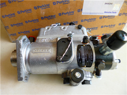
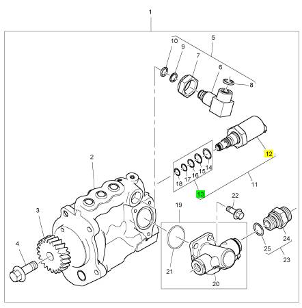
Perkins珀金斯1600柴油发动机7093281 C92高压燃油泵
详细描述
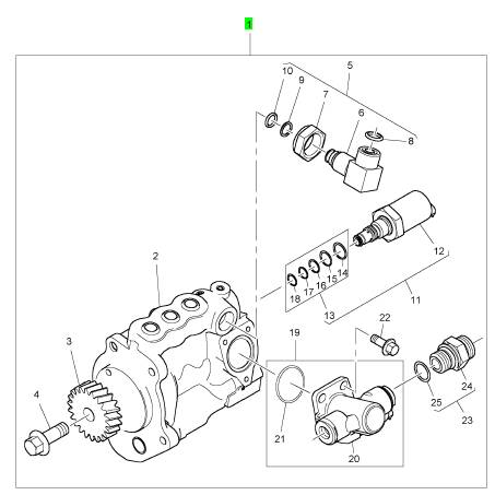
项目 零配件号码 新件号 描述
1 1893766 C91 1 7093281 C92 高压燃油泵
项目 零配件号码 新件号 描述
2 1 高压燃油泵
3 1841116 C3 1 1841116 C3 燃油喷射泵传动机构
4 1841488 C1 1 1841488 C1 螺旋
5 1885863 C91 1 1885863 C91 肘管
11 1889325 C92 1 1889325 C94 停机电磁阀
19 1876108 C92 1 2511369 C91 提升泵装备
22 1817953 C1 3 1817953 C1 公制的螺拴
23 1841487 C91 2 1841487 C91 承接器
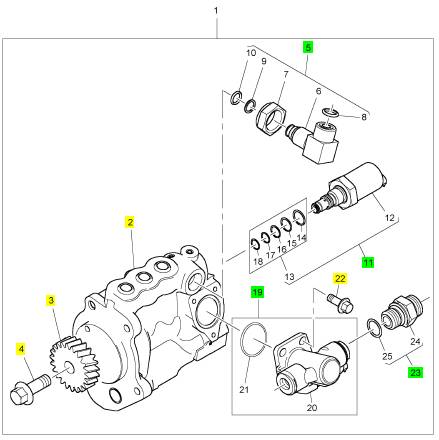
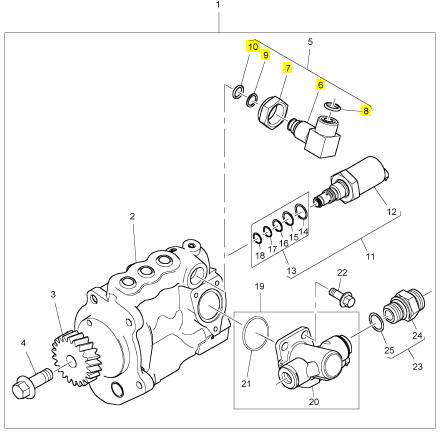
项目 零配件号码 新件号 描述
6 1 肘管
7 1883006 C1 1 1883006 C1 螺帽
8 1879755 C1 1 1879755 C1 密封O型圈
9 1879756 C1 1 1879756 C1 密封O型圈
10 1879755 C1 1 1879755 C1 密封O型圈
项目 零配件号码 新件号 描述
12 1 停机电磁阀
13 1889027 C91 1 1889027 C91 密封装备
项目 零配件号码 新件号 描述
1 1839032 C91 1 1839032 C91 联结器
4 1655349 C1 1 1655349 C1 帽
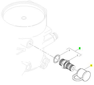
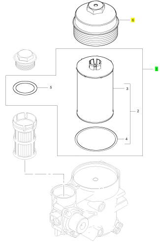
项目 零配件号码 新件号 描述
1 1878042 C92 1 1878042 C92 燃油过滤器
6 1837497 C1 1 1837497 C1 帽
|
KENR8772 |
|
59 Testing and Adjusting Section |
|
Before you begin inspection of the turbocharger, be sure that the inlet air restriction is within the specifications for your engine. Be sure that the exhaust system restriction is within the specifications for your engine. Refer to Systems Operation, Testing and Adjusting, “Air Inlet and Exhaust System - Inspect”. |
|
3. Turn the rotating assembly by hand. While you turn the assembly, push the assembly sideways . The assembly should turn freely. The compressor wheel should not rub the compressor housing. Replace the turbocharger if the compressor wheel rubs the compressor wheel housing. If there is no rubbing or scraping, go to Step 4. |
|
The condition of the turbocharger will have definite effects on engine performance. Use the following inspections and procedures to determine the condition of the turbocharger. |
|
4. Inspect the compressor and the compressor wheel housing for oil leakage. An oil leak from the compressor may deposit oil in the aftercooler. Drain and clean the aftercooler if you find oil in the aftercooler. |
|
• Inspection of the Compressor and the Compressor Housing |
|
a. Check the oil level in the crankcase. If the oil |
|
level is too high, adjust the oil level. |
|
• Inspection of the Turbine Wheel and the Turbine Housing |
|
b. Inspect the air cleaner element for restriction. If |
|
restriction is found, correct the problem. |
|
Inspection of the Compressor and the Compressor Housing |
|
c. Inspect the engine crankcase breather. Clean the engine crankcase breather or replace the engine crankcase breather if the engine crankcase breather is plugged. |
|
d. Remove the oil drain line for the turbocharger. Inspect the drain opening. Inspect the oil drain line. Inspect the area between the bearings of the rotating assembly shaft. Look for oil sludge. Inspect the oil drain hole for oil sludge. Inspect the oil drain line for oil sludge in the drain line. If necessary, clean the rotating assembly shaft. If necessary, clean the oil drain hole. If necessary, clean the oil drain line. |
|
e. If Steps 4.a through 4.d did not reveal the source of the oil leakage, the turbocharger has internal damage. Replace the turbocharger. |
|
Inspection of the Turbine Wheel and the Turbine Housing |
|
Remove the air piping from the turbine housing. |
|
g02317693 |
|
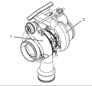
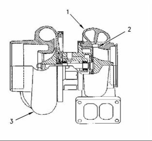
Illustration 49 |
|
Typical example |
|
(1) Compressor housing (2) Turbine housing |
|
Remove air piping from the compressor inlet. |
|
1. Inspect the compressor wheel for damage from a foreign object. If there is damage, determine the source of the foreign object. As required, clean the inlet system and repair the intake system. Replace the turbocharger. If there is no damage, go to Step 3. |
|
2. Clean the compressor wheel and clean the compressor housing if you find buildup of foreign material. If there is no buildup of foreign material, go to Step 3. |
|
This document is printed from SPI². Not for RESALE |
![]()
![]()
|
60 |
|
KENR8772 |
|
Testing and Adjusting Section |
|
b. If crankcase pressure is high, or if the oil drain is restricted, pressure in the center housing may be greater than the pressure of turbine housing (1). Oil flow may be forced in the wrong direction and the oil may not drain. Check the crankcase pressure and correct any problems. |
|
c. If the oil drain line is damaged, replace the oil drain line. |
|
d. Check the routing of the oil drain line. Eliminate any sharp restrictive bends. Make sure that the oil drain line is not too close to the engine exhaust manifold. |
|
e. If Steps 4.a through 4.d did not reveal the source of the oil leakage, turbocharger (3) has internal damage. Replace turbocharger (3). |
|
Check the Wastegate for Proper Operation |
|
g00763164 |
|
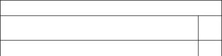
Illustration 50 |
|
Typical example |
|
Table 3 |
|
(1) Turbine Housing (2) Turbine Wheel (3) Turbocharger |
|
Required Tools Part |
|
Tool A |
|
Number |
|
Part Description |
|
Qty |
|
1. Inspect the turbine for damage by a foreign object. If there is damage, determine the source of the foreign object. Replace turbocharger (3). If there is no damage, go to Step 2. |
|
21825617 |
|
Dial Gauge |
|
1 |
|
2. Inspect turbine wheel (2) for buildup of carbon and other foreign material. Inspect turbine housing (1) for buildup of carbon and foreign material. Clean turbine wheel (2) and clean turbine housing (1) if you find buildup of carbon or foreign material. If there is no buildup of carbon or foreign material, go to Step 3. |
|
3. Turn the rotating assembly by hand. While you turn the assembly, push the assembly sideways. The assembly should turn freely. Turbine wheel (2) should not rub turbine wheel housing (1). Replace turbocharger (3) if turbine wheel (2) rubs turbine housing (1). If there is no rubbing or scraping, go to Step 4. |
|
4. Inspect the turbine and turbine housing (1) for oil leakage. Inspect the turbine and turbine housing (1) for oil coking. Some oil coking may be cleaned. Heavy oil coking may require replacement of the turbocharger. If the oil is coming from the turbocharger center housing go to Step 4.a. |
|
g02317713 |
|
Illustration 51 |
|
Typical example |
|
1. Disconnect the pipe for the boost sensor (2) at the wastegate actuator (3). Connect an air supply to the wastegate actuator that can be adjusted accurately. |
|
a. Remove the oil drain line for the turbocharger. Inspect the drain opening. Inspect the area between the bearings of the rotating assembly shaft. Look for oil sludge. Inspect the oil drain hole for oil sludge. Inspect the oil drain line for oil sludge. If necessary, clean the rotating assembly shaft. If necessary, clean the drain opening. If necessary, clean the drain line. |
|
2. Install Tooling (A) to the turbocharger so that the end of the actuator rod (1) is in contact with Tooling (A). This will measure axial movement of the actuator rod (1). |
|
This document is printed from SPI². Not for RESALE |
![]()
![]()
![]()
|
KENR8772 |
|
61 Testing and Adjusting Section |
|
3. Slowly apply air pressure to the wastegate so that the actuator rod (3) moves 0.4 mm (0.016 inch). Refer to Specifications, “Turbocharger” for the correct pressure for the wastegate. Ensure that the dial indicator returns to zero when the air pressure is released. Repeat the test several times. This will ensure that an accurate reading is obtained. |
|
Air Under Water Leak Test Procedure. |
|
4. If the operation of the wastegate is not correct, engineering to advise if the turbocharger should be replaced or the actuator rod should be replaced. |
|
5. Repeat steps 1 to 4 in order to repeat the pressure test. |
|
6. If the air pressure is correct, remove the air supply. Remove Tooling (A). Install the pipe for the boost sensor (2). |
|
i02788813 |
|
Exhaust Temperature - Test |
|
g02390879 |
|
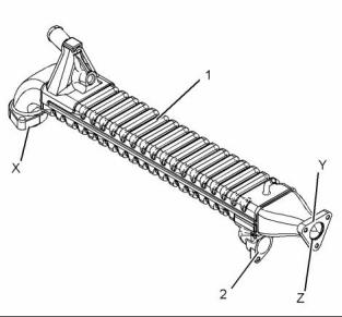
Illustration 52 |
|
Typical example |
|
Table 4 |
|
1. Install Tooling (A) at positions (X) and (Y) to the exhaust cooler (NRS) (1). Tighten the bolts that secure the plates to a maximum torque of 20 N·m (15 lb ft). |
|
Required Tools |
|
Tool |
|
Part Number |
|
Part Description |
|
Qty |
|
A |
|
- |
|
Infrared Thermometer |
|
1 |
|
Note: A plug is required for sealing the open end of the inlet side (2) of the exhaust cooler (NRS) (1) for pressure testing. |
|
When the engine runs, the temperature of an exhaust manifold port can indicate the condition of a fuel injection nozzle. |
|
2. Connect an air supply to pressure test plate at |
|
position (Z). Apply a pressure of 207 kPa (30 psi). |
|
A low temperature indicates that no fuel is flowing to the cylinder. An inoperative fuel injection nozzle or a problem with the fuel injection pump could cause this low temperature. |
|
3. While the exhaust gas cooler (NRS) is still pressurized, submerge the cooler in water that is at ambient temperature. |
|
A very high temperature can indicate that too much fuel is flowing to the cylinder. A malfunctioning fuel injection nozzle could cause this very high temperature. |
|
4. Allow the exhaust gas cooler (NRS) to settle in order for the air that is trapped to escape. |
|
5. Observe the exhaust gas cooler (NRS) for air bubbles that indicate a leak. If air bubbles are seen within 3 minutes, this indicates a leak with the exhaust gas cooler (NRS). Note the location or the origin of the leak. Record this information. |
|
Use Tooling (A) to check exhaust temperature. |
|
i04201411 Exhaust Cooler (NRS) - Test (If Equipped) |
|
6. If no bubbles are detected after 3 minutes, the exhaust gas cooler (NRS) is reusable. |
|
7. Remove the exhaust gas cooler (NRS) from the water. If the exhaust gas cooler (NRS) does not leak, the problem may be elsewhere in the cooling system or the engine. Refer the service manual in order to check for leakage. If the exhaust gas cooler (NRS) does leak, the exhaust gas cooler (NRS) should be replaced. |
|
Table 5 |
|
Required Tools |
|
Tool |
|
Part Number |
|
Part Description |
|
Qty |
|
A |
|
27610408 |
|
Pressure Test Plates |
|
1 |
|
This document is printed from SPI². Not for RESALE |
![]()
![]()
|
62 |
|
KENR8772 |
|
Testing and Adjusting Section |
|
i04935303 |
|
i04032141 |
|
Engine Crankcase Pressure (Blowby) - Test |
|
Engine Valve Lash - Inspect/Adjust |
|
Table 6 |
|
Required Tools Part |
|
Tool |
|
Number |
|
Part Name |
|
Quantity |
|
A |
|
- |
|
Pressure Gauge |
|
1 |
|
Damaged pistons or rings can cause too much pressure in the crankcase. This condition will cause the engine to run rough. There will be more than the normal amount of fumes (blowby) rising from the crankcase breather. The breather can then become restricted in a short time, causing oil leakage at gaskets and seals that would not normally have leakage. Blowby can also be caused by worn valve guides or by a failed turbocharger seal. |
|
g01284058 |
|
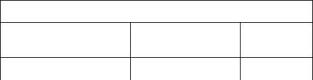
Illustration 53 |
|
Cylinder and valve location |
|
(A) Inlet valve |
|
(B) Exhaust valve |
|
1. Install Tooling (A) to the most convenient location on the output tube for the crankcase breather or the breather hose. A suitable adaptor may be required in addition to the pressure gauge. |
|
If the valve lash requires adjustment several times in a short time period, excessive wear exists in a different part of the engine. Find the problem and make necessary repairs in order to prevent more damage to the engine. |
|
2. Operate the engine at a speed of 1500 rpm or 1800 rpm with no load. Allow the gauge reading to stabilize before taking the pressure reading. |
|
Not enough valve lash can be the cause of rapid wear of the camshaft and valve lifters. Not enough valve lash can indicate that the seats for the valves are worn. |
|
The engine blowby should be less than 50 L/min (13 US gpm) for a new engine. |
|
The maximum engine blowby should be 200 L/min (53 US gpm). |
|
Valves beco, me worn due to the following causes: • Fuel injection nozzles that operate incorrectly |
|
Note: Do not use the data alone to determine if the engine should be overhauled. Other indicators such as high oil consumption, low power, hard starting, and excessive fuel consumption must be considered. |
|
• Excessive dirt and oil are present on the filters for the inlet air. |
|
• Incorrect fuel settings. |
|
After a new engine is used for a short time, the blowby can decrease as the rings are seated. New engines should be checked for blowby during all maintenance checks. As the piston rings and cylinder walls wear, the blowby will gradually increase. |
|
• The load capacity of the engine is frequently exceeded. |
|
Too much valve lash can cause broken valve stems, springs, and spring retainers. Too much valve lash can be an indication of the following problems: |
|
The blowby on a worn engine may be two times or more than the blowby of a new engine and may indicate the need for an overhaul. |
|
• Worn camshaft and valve lifters • Worn rocker arms |
|
• Bent pushrods |
|
• Broken socket on the upper end of a pushrod |
|
• Loose adjustment screw for the valve lash |
|
This document is printed from SPI². Not for RESALE |
![]()
![]()
|
KENR8772 |
|
63 Testing and Adjusting Section |
|
If the camshaft and valve lifters show rapid wear, look for fuel in the lubrication oil or dirty lubrication oil as a possible cause. |
|
3. Measure the valve lash for the valve when the engine is at TC compression stroke according to Table 8. If necessary, adjust the valves according to Table 8. |
|
Valve Lash Check |
|
a. Loosen the valve adjustment screw locknut |
|
that is on the adjustment screw. |
|
An adjustment is NOT NECESSARY if the measurement of the valve lash is in the acceptable range. Check the valve lash while the engine is stopped. The temperature of the engine does not change the valve lash setting. |
|
b. Place an appropriate feeler gauge between the rocker arm and the valve. Turn the adjustment screw while the valve adjustment screw locknut is being held from turning. Adjust the valve lash until the correct specification is achieved. |
|
If the measurement is not within the acceptable clearance, adjustment is necessary. Refer to “Valve Lash Adjustment”. |
|
c. After each adjustment, tighten the valve adjustment screw locknut while you hold the valve adjustment screw from turning. |
|
Valve Lash Adjustment |
|
4. Rotate the crankshaft in the direction of engine rotation to TC exhaust stroke (360 degrees from TC compression stroke). |
|
Table 7 |
|
Inlet Valves |
|
Exhaust Valves |
|
0.48 mm (0.019 inch) |
|
0.48 mm (0.019 inch) |
|
Table 9 |
|
Valve Lash |
|
TC Exhaust |
|
Inlet Valves |
|
Exhaust Valves |
|
TC Compression Stroke |
|
Stroke(1) Valve Lash Cylinders |
|
1-2-4 3-5-6 |
|
1-3-5 2-4-6 |
|
0.48 mm (0.019 inch) |
|
0.48 mm (0.019 inch) |
|
TC Exhaust |
|
Stroke |
|
(1) |
|
3-5-6 |
|
2-4-6 |
|
Firing Order |
|
1-5-3-6-2-4 (2) |
|
(1) 360° from TC compression stroke |
|
(1) 360° from TC compression stroke |
|
(2) The No. 1 Cylinder is at the front of the engine. |
|
5. Measure the valve lash for the valves when the engine is at TC exhaust stroke according to Table 9. If necessary, adjust the valves according to Table 9. |
|
Accidental engine starting can cause injury or death to personnel. |
|
a. Loosen the valve adjustment screw locknut that is on the adjustment screw. |
|
To prevent accidental engine starting, turn the ig- nition switch to the OFF position and place a do not operate tag at the ignition switch location. |
|
b. Place an appropriate feeler gauge between the rocker arm and the valve. Turn the adjustment screw while the valve adjustment screw locknut is being held from turning. Adjust the valve lash until the correct specification is achieved. |
|
1. Remove the valve mechanism cover. Refer to Disassembly and Assembly, “Valve Mechanism Cover - Remove” For the removal procedure. |
|
c. After each adjustment, tighten the valve adjustment screw locknut while you hold the valve adjustment screw from turning. |
|
2. Rotate the crankshaft in the direction of engine rotation until the inlet valve of the No. 6 cylinder has opened and the exhaust valve of the No. 6 cylinder has not completely closed. The engine is now at TC compression stroke. |
|
6. Install the valve mechanism cover. Refer to Disassembly and Assembly, “Valve Mechanism Cover - Install” for the installation procedure. |
|
Table 8 |
|
TC Compression Stroke |
|
Inlet Valves |
|
Exhaust Valves |
|
0.48 mm (0.019 inch) |
|
0.48 mm (0.019 inch) |
|
Valve Lash Cylinders |
|
1-2-4 |
|
1-3-5 |
|
This document is printed from SPI². Not for RESALE |
![]()

![]()
![]()


|
64 |
|
KENR8772 |
|
Testing and Adjusting Section |
|
i04201709 |
|
For the wear limits for the inlet valves and exhaust |
|
valves, refer to Specifications, “Cylinder Head”. |
|
Valve Depth - Inspect |
|
5. Check each valve for cracks. Check the stems of the valves for wear. Ensure that the valves are the correct fit in the valve guides. Refer to Systems Operation, Testing and Adjusting, “Valve Guide - Inspect” for the procedure to inspect the valve guides. |
|
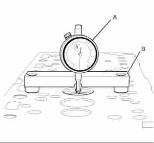
Table 10 |
|
Required Tools |
|
Tool A |
|
Part Number 21825617 21825496 |
|
Part Description Dial gauge Dial gauge Holder |
|
Qty 1 |
|
6. Check the load on the valve springs. Refer to Specifications, “Cylinder Head Valves” for the correct lengths and specifications for the valve springs. |
|
B |
|
1 |
|
i04201679 |
|
Valve Guide - Inspect |
|
Perform this test in order to determine if a valve guide should be replaced. |
|
1. Clean valve guides with soap, water, and a nylon brush. |
|
2. Position an inspection light at the bottom of valve guide bores. Inspect bores for burning or cracks. Replace any damaged valve guides. |
|
3. Measure the inside diameter of each valve guide with a ball gauge or small hole gauge set and an outside micrometer. |
|
g01201916 |
|
Illustration 54 |
|
Typical example |
|
4. If valve guide bore, taper, or out of round exceeds the correct specification, replace the valve guide. Refer to Specifications for the correct specifications. |
|
1. Ensure that the faces of the valves are clean. Ensure that the bottom face of the cylinder head is clean. Ensure that the cylinder head is not distorted. Refer to Systems Operation, Testing and Adjusting, “Cylinder Head - Inspect” for the procedure to measure flatness of the cylinder head. |
|
5. Measure the valve guides within 0.64 mm (0.025 inch) of each end and 90 degrees from crankshaft center line. Record the measurements. Determine the valve stem-to-guide running clearance after inspecting the cylinder head valves. |
|
2. Use the Tooling (A) to check the depths of the inlet valves and the exhaust valves below the face of the cylinder head. Use Tooling (B) to zero Tooling (A). |
|
3. For the minimum and maximum limits for a new engine for the inlet valves and the exhaust valves, refer to Specifications, “Cylinder Head”. |
|
4. Service wear occurs on an engine which has been in operation. If the valve depth below the cylinder head face on a used engine exceeds the specification for service wear, the following components must be replaced. |
|
• Valves |
|
• Valve inserts |
|
This document is printed from SPI². Not for RESALE |
![]()

![]()
|
KENR8772 |
|
65 Testing and Adjusting Section |
|
Lubrication System Engine Oil Pressure - Test Low Oil Pressure |
|
Table 12 |
|
Minimum Expected Oil Pressure with Lubricant Viscosity of 10W30 |
|
i04205309 |
|
Sales Model |
|
Engine Speed (rpm) |
|
Pressure |
|
1600D 1600D 1600A 1600A |
|
1500 1800 1500 1800 |
|
221 kPa (32 psi) 228 kPa (33 psi) 241 kPa (35 psi) 255 kPa (37 psi) |
|
The following conditions will cause low oil pressure. • The oil level is low in the crankcase. |
|
A suitable pressure gauge can be used in order to test the pressure of the lubrication system. |
|
• A restriction exists on the oil suction screen. • Connections in the oil lines are leaking. • The connecting rod or the main bearings are worn. • The rotors in the oil pump are worn. |
|
High Oil Pressure |
|
High oil pressure can be caused by the following condition. |
|
• Excessive sludge exists in the oil which makes the viscosity of the oil too high. |
|
• The oil pressure regulating valve is operating incorrectly. |
|
i04201372 |
|
A worn oil pressure regulating valve can allow oil to leak through the valve which lowers the oil pressure. Visually inspect the pressure regulating valve for damage. If the pressure regulating valve is damaged, the pressure regulating valve must be replaced. |
|
Engine Oil Pump - Inspect |
|
If any part of the oil pump is worn enough in order to affect the performance of the oil pump, the oil pump must be replaced. |
|
The pressure regulating valve operates at a pressure of 331 kPa (48 psi). |
|
Perform the following procedures in order to inspect the oil pump. Refer to Specifications, “Engine Oil Pump” for clearances and torques. |
|
Refer to tables 11 and 12 for the minimum oil pressure at certain engine speeds and at normal operating temperature. A lower pressure is normal at low idle. |
|
1. Remove the oil pump from the engine. Refer to Disassembly and Assembly, “Engine Oil Pump - Remove” for the correct procedure. Remove the cover of the oil pump. |
|
Table 11 |
|
Minimum Expected Oil Pressure with Lubricant Viscosity of 15W40 |
|
Sales Model |
|
Engine Speed (rpm) |
|
Pressure |
|
1600D 1600D 1600A 1600A |
|
1500 1800 1500 1800 |
|
234 kPa (34 psi) 234 kPa (34 psi) 255 kPa (37 psi) 255 kPa (37 psi) |
|
This document is printed from SPI². Not for RESALE |