 English
 Espaol
 Franais
 阿拉伯
阿拉伯 中文
中文 Deutsch
 Italiano
 Português
 日本
日本 韩国
韩国 български
 hrvatski
 esky
esky Dansk
Dansk Nederlands
 suomi
suomi Ελληνικ
 印度
印度 norsk
norsk Polski
 Roman
Roman русский
 Svenska
Perkins珀金斯1600柴油发动机1840171 C6飞轮壳供应商,Perkins珀金斯1600柴油发动机1840171 C6飞轮壳技术价格规格咨询服务,Perkins珀金斯1600柴油发动机1840171 C6飞轮壳零配件供应,Perkins珀金斯1600柴油发动机1840171 C6飞轮壳售后服务中心,Perkins珀金斯1600柴油发动机1840171 C6飞轮壳,Perkins珀金斯1600柴油发动机1840171 C6飞轮壳详细的技术参数,

产品中心
Perkins珀金斯1600柴油发动机1840171 C6飞轮壳
详细描述
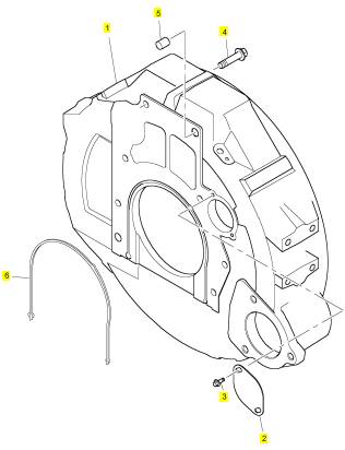
项目 零配件号码 新件号 描述
1 1840171 C6 1 1840171 C6 飞轮壳
2 686702 C2 1 686702 C2 板
3 1817953 C1 2 1817953 C1 公制的螺拴
4 1820606 C1 8 1820606 C1 公制的螺拴
5 1822086 C1 2 1822086 C1 合钉
6 1841227 C1 1 1841227 C1 密封垫片 - 飞轮壳
|
8. Blow heat exchanger oil passages dry using filtered compressed air. |
|
3. Inspect the water pump shaft for unusual noise, excessive looseness and/or vibration of the bearings. |
|
i04112270 |
|
4. Inspect the pulley for the water pump for wear or |
|
Water Temperature Regulator - Test |
|
for damage. |
|
Personal injury can result from escaping fluid un- der pressure. |
|
If a pressure indication is shown on the indicator, push the release valve in order to relieve pressure before removing any hose from the radiator. |
|
1. Remove the water temperature regulator from the engine. |
|
2. Heat water in a suitable container until the temperature is 98 °C (208 °F). |
|
3. Hang the water temperature regulator in the container of water. The water temperature regulator must be below the surface of the water and away from the sides and the bottom of the container. |
|
4. Keep the water at the correct temperature for 10 minutes. |
|
5. After 10 minutes, remove the water temperature regulator. Ensure that the water temperature regulator is open. |
|
Replace the water temperature regulator if the water temperature regulator is not open at the specified temperature. Refer to Specifications, “Water Temperature Regulator”. |
|
i04201332 |
|
Water Pump - Inspect |
|
1. Inspect the water pump for leaks at vent hole. The water pump seal is lubricated by coolant in the cooling system. A normal condition is for a small amount of leakage to occur as the engine cools down and the parts contract. |
|
2. For the correct procedures to remove and install the water pump, refer to Disassembly and Assembly, “Water Pump - Remove ” and Disassembly and Assembly, “Water Pump - Install”. |
|
This document is printed from SPI². Not for RESALE |
![]()
![]()
![]()
|
KENR8772 |
|
75 Testing and Adjusting Section |
|
Basic Engine |
|
3. Install a new intermediate compression ring to the piston. Refer to Disassembly and Assembly, “Pistons and Connecting Rods - Assemble” for the correct procedure. |
|
i04032199 |
|
Piston Ring Groove - Inspect |
|
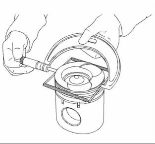
4. Check the clearance for the piston ring by placing a suitable feeler gauge (1) between the piston groove and the top of piston ring. Refer to Specifications, “Piston and Rings” for the dimensions. |
|
Table 17 |
|
Required Tools |
|
5. Install a new oil control ring to the piston. Refer to Disassembly and Assembly, “Pistons and Connecting Rods - Assemble” for the correct procedure. |
|
Tool |
|
Part Number |
|
Part Description |
|
Qty |
|
A |
|
27610407 |
|
Piston Groove Gauge |
|
1 |
|
Note: Tooling (A) can only be used to measure the top compression ring groove. |
|
Inspect the Piston and the Piston Rings |
|
1. Check the piston for wear and other damage. |
|
2. Check that the piston rings are free to move in the grooves and that the rings are not broken. |
|
Inspect the Clearance of the Piston Ring |
|
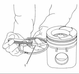
1. Remove the piston rings and clean the grooves and the piston rings. |
|
g02388617 |
|
Illustration 60 |
|
Typical example |
|
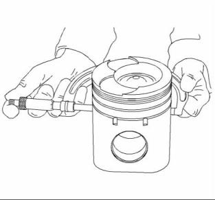
6. Check the clearance for the piston ring by placing a suitable feeler gauge (1) between the piston groove and the top of piston ring. Refer to illustration 60. Refer to Specifications, “Piston and Rings” for the dimensions. |
|
g02388577 |
|
Illustration 59 |
|
Typical example |
|
2. Install Tooling (A) to the top compression ring groove. Measure and record the overall diameter of the piston and the gauge. Refer to illustration 59. Refer to Specifications, “Piston and Rings” for the dimensions. This document is printed from SPI². Not for RESALE |
![]()
![]()
![]()
|
76 |
|
KENR8772 |
|
Testing and Adjusting Section |
|
Inspect the Piston Skirt |
|
i04201791 |
|
Connecting Rod - Inspect |
|
These procedures determine the following characteristics of the connecting rod: |
|
• The distortion of the connecting rod |
|
• The parallel alignment of the bores of the connecting rod |
|
Note: If the crankshaft or the cylinder block are replaced, the piston height for all cylinders must be measured. |
|
Note: When the piston pin is installed, always install new retaining rings on each end of the piston pin. |
|
Distortion of The Connecting Rod |
|
g02388557 |
|
Illustration 61 |
|
1. Use the following tools in order to measure the distances for the connecting rod (2) which are specified in Illustration 63: |
|
Typical example |
|
1. Using a suitable micrometer to measure and record the diameter of the piston skirt. Refer to illustration 61. Measured at 90 degrees from the gudgeon pin, at a point 27.43 mm (1.08 inch) below the oil control ring. |
|
• Appropriate gauges for measuring distance • Measuring pins (1) |
|
Inspect the Piston Ring End Gap |
|
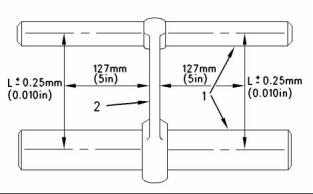
g00326423 |
|
Illustration 63 |
|
Measure the connecting rod for distortion. |
|
(1) Measuring pins (2) Connecting rod |
|
g00782363 |
|
Illustration 62 |
|
(L) The length between the centers of the piston pin bearing and the crankshaft journal bearing is shown in Illustration 63. |
|
Typical example |
|
1. Clean all carbon from the top of the cylinder bores. |
|
2. Measure the connecting rod for distortion and |
|
parallel alignment between the bores. |
|
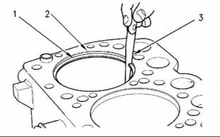
2. Place each piston ring (1) in the cylinder bore just |
|
below the cylinder ring ridge (2). |
|
The bores for the crankshaft bearing and the bearing for the piston pin must be square and parallel with each other within the required limits. If the piston pin bearing is removed, the limit “L” is the following value: ± 0.25 mm (± 0.010 inch) |
|
3. Use a suitable feeler gauge (3) to measure piston ring end gap. Refer to Specifications, “Piston and Rings” for the dimensions. |
|
Note: The coil spring must be removed from the oil control ring before the gap of the oil control ring is measured. |
|
The limits are measured at a distance of 127 mm (5.0 inch) from each side of the connecting rod. This document is printed from SPI². Not for RESALE |
![]()
![]()
![]()
![]()
|
KENR8772 |
|
77 Testing and Adjusting Section |
|
If the piston pin bearing is not removed, the limit “L” is the following value: ± 0.06 mm (± 0.0024 inch) |
|
3. The top deck of the cylinder block must not be machined. This will affect the depth of the cylinder liner flange and the piston height above the cylinder block. |
|
L is equal to 219.456 ± 0.051 mm (8.63998 ± 0.00201 inch). |
|
4. Check the front camshaft bearing for wear. Refer to Specifications, “Camshaft Bearings” for the correct specification of the camshaft bearing. If a new bearing is needed, use a suitable adapter to press the bearing out of the bore. Ensure that the oil hole in the new bearing faces the front of the block. The oil hole in the bearing must be aligned with the oil hole in the cylinder block. The bearing must be aligned with the face of the recess. |
|
3. Inspect the piston pin bearing and the piston pin for wear. |
|
4. Measure the clearance of the piston pin in the piston pin bearing. Refer to the Specifications, “Connecting Rod” for dimensions. |
|
i04112273 Connecting Rod Bearings - Inspect |
|
i04203728 |
|
Cylinder Head - Inspect |
|
The connecting rod bearings fit tightly in the bore in the rod. If the bearing joints are worn, check the bore size. An indication of wear can be installed components that are loose. |
|
1. Remove the cylinder head from the engine. Refer to Disassembly and Assembly, “Cylinder Head - Remove” for the correct procedure. |
|
2. Remove the water temperature regulator housing. Refer to Disassembly and Assembly for the correct procedure. |
|
Connecting rod bearings are available with smaller inside diameters than the original size bearings. These bearings are for crankshafts that have been ground. |
|
3. Inspect the cylinder head for signs of gas or |
|
coolant leakage. |
|
If necessary, replace the connecting rod bearings. Refer to Disassembly and Assembly, “Connecting Rod Bearings - Remove” and Disassembly and Assembly, “Connecting Rod Bearings - Install” for the correct procedure. |
|
4. Remove the valve springs and valves. |
|
5. Clean the bottom face of the cylinder head thoroughly. Clean the coolant passages and the lubricating oil passages. Make sure that the contact surfaces of the cylinder head and the cylinder block are clean, smooth, and flat. |
|
i04112351 |
|
Main Bearings - Inspect |
|
6. Inspect the bottom face of the cylinder head for pitting, corrosion, and cracks. Inspect the area around the valve seat inserts and the holes for the fuel injection nozzles carefully. |
|
Main bearings are available with smaller inside diameters than the original size bearings. These bearings are for crankshafts that have been ground. |
|
7. Test the cylinder head for leaks at a pressure of |
|
124 to 138 kPa (18 to 20 psi). |
|
If necessary, replace the main bearings. Refer to Disassembly and Assembly, “Crankshaft Main Bearings - Remove and Install” for the correct procedure. |
|
Check the following: • Fuel injector nozzle sleeve areas • Valve ports |
|
i04112354 |
|
Cylinder Block - Inspect |
|
• Upper deck |
|
• Lower deck |
|
If any leaks are observed from any fuel injector nozzle sleeves, replace injector sleeves and pressure test the cylinder head again. If cylinder head leakage is observed, replace the cylinder head. |
|
1. Clean all of the coolant passages and the oil passages. |
|
2. Check the cylinder block for cracks and damage. This document is printed from SPI². Not for RESALE |
![]()
|
78 |
|
KENR8772 |
|
Testing and Adjusting Section |
|
i04041560 |
|
Cylinder Liner Projection - Inspect |
|
Table 18 |
|
Required Tools Part Number Part Description |
|
Tool |
|
Qty |
|
Clamp Bolt (M16 x 2 mm) |
|
A |
|
29990021 |
|
6 |
|
B C D |
|
CH12571 GE50006 GE50007 |
|
Hard Washer Clamp washer Clamp washer |
|
- |
|
6 6 |
|
Cylinder liner projection tool |
|
E |
|
GE50002 |
|
1 |
|
g02278893 |
|
Illustration 64 |
|
1. Clean the cylinder liner flange and the cylinder block surface. Remove any nicks on the top of the cylinder block (1). |
|
Flatness of the cylinder head (typical example) |
|
(A) Side to side (B) End to end (C) Diagonal |
|
2. Install the cylinder liners to the cylinder block without seals or bands. Ensure that the cylinder liners are installed to the original positions. |
|
8. Measure the cylinder head for flatness. Use a straight edge and a feeler gauge to check the cylinder head for flatness. |
|
• Measure the cylinder head from one side to the opposite side (A). |
|
• Measure the cylinder head from one end to the opposite end (B). |
|
• Measure the cylinder head from one corner to the opposite corner (C). |
|
Refer to Specifications, “Cylinder Head” for the requirements of flatness. |
|
Resurfacing the Cylinder Head |
|
Illustration 65 |
|
g01944741 |
|
The bottom face of cylinder head can be resurfaced if any of the following conditions exist: |
|
3. Install Tooling (B), Tooling (C), and Tooling (D) to Tooling (A). Install Tooling (A) around the liner (2). Refer to illustration 65. |
|
• The bottom face of the cylinder head is not flat within the specifications. |
|
4. Tighten the clamp bolts to a torque of 14 N·m (10 lb ft). |
|
• The bottom face of the cylinder head is damaged by pitting, corrosion, or wear. |
|
5. Use Tooling (E) to measure the cylinder liner projection at three locations evenly spaced around the cylinder sleeve. |
|
Note: The thickness of the cylinder head must not be less than 159.97 mm (6.298 inch) after the cylinder head has been machined. |
|
6. Record the measurements for the cylinder. 7. Repeat steps 3 to 6 for each cylinder. |
|
8. Add the three readings for each cylinder. Divide the sum by three in order to find the average. This document is printed from SPI². Not for RESALE |