 English
 Espaol
 Franais
 阿拉伯
阿拉伯 中文
中文 Deutsch
 Italiano
 Português
 日本
日本 韩国
韩国 български
 hrvatski
 esky
esky Dansk
Dansk Nederlands
 suomi
suomi Ελληνικ
 印度
印度 norsk
norsk Polski
 Roman
Roman русский
 Svenska
Perkins珀金斯1600柴油发动机7082947 C92摇臂室盖供应商,Perkins珀金斯1600柴油发动机7082947 C92摇臂室盖技术价格规格咨询服务,Perkins珀金斯1600柴油发动机7082947 C92摇臂室盖零配件供应,Perkins珀金斯1600柴油发动机7082947 C92摇臂室盖售后服务中心,Perkins珀金斯1600柴油发动机7082947 C92摇臂室盖,Perkins珀金斯1600柴油发动机7082947 C92摇臂室盖详细的技术参数,

产品中心
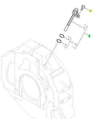
Perkins珀金斯1600柴油发动机7082947 C92摇臂室盖
详细描述
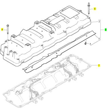
项目 零配件号码 新件号 描述
1 7082947 C92 1 7082947 C92 摇臂室盖
1 7082947 C91 1 7082947 C91 摇臂室盖
5 1833412 C1 9 1833412 C1 螺拴
6 1818231 C1 1 1818231 C1 螺拴
7 1 密封垫片
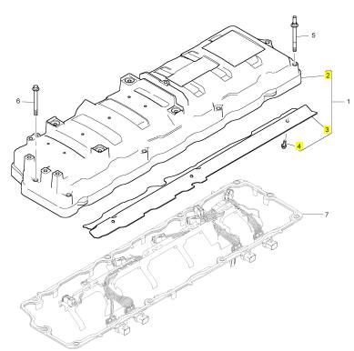
项目 零配件号码 新件号 描述
2 1 摇臂室盖
3 7082928 C1 1 7082928 C1 挡板
4 1817953 C1 3 1817953 C1 公制的螺拴
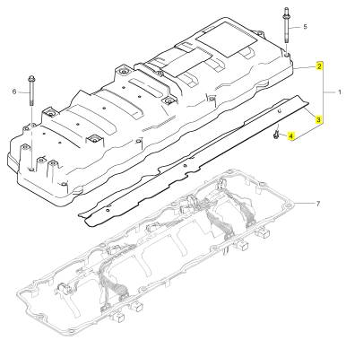
项目 零配件号码 新件号 描述
2 1 摇臂室盖
3 7082928 C1 1 7082928 C1 挡板
4 1817953 C1 3 1817953 C1 公制的螺拴
项目 零配件号码 新件号 描述
1 1835985 C92 1 1835985 C92 感应传感器
6 1817953 C1 1 1817953 C1 公制的螺拴
|
roubleshooting |
|
1600 Series Industrial Engine |
|
XGA (Engine) XGB (Engine) XGD (Engine) XGE (Engine) XGF (Engine) XGH (Engine) |
|
This document has been printed from SPI2. NOT FOR RESALE. |
![]()
![]()
![]()
![]()

|
Important Safety Information |
|
Most accidents tha t involve produc t op eration, ma intena nc e and repair are caus ed by failure to ob serve basic safety rules or precautions . An accident can often be avoided by recog nizing pote ntially ha za rdous situations before an accident oc curs . A person mus t be alert to pote ntial ha za rds. This person should also ha ve the ne cessary training, skills and tools to perform the se func tions properly. |
|
Improper operation, lubrication, maintenance or repair of this product can be dangerous and could result in injury or death. |
|
Do not operate or perform any lubrication, maintenance or repair on this product, until you have read and understood the operation, lubrication, maintenance and repair information. |
|
Sa fety precautions and warning s are provided in this ma nua l and on the produc t. If the se ha za rd warning s are not he eded, bod ily injury or death could oc cur to you or to othe r persons . |
|
The ha za rds are identified by the “Safety Alert Symb ol” and followed by a “Signa l Word” suc h as “DANGER”, “WARNING” or “CAUTION”. The Sa fety Alert “WARNING” label is shown below. |
|
The me aning of this safety alert symb ol is as follows: |
|
Attention! Become Alert! Your Safety is Involved. |
|
The me ssage tha t appears und er the warning explains the ha za rd and can be either written or pictorially presente d. |
|
Op erations tha t ma y caus e produc t dama ge are identified by “NOTICE” labels on the produc t and in this pub lication. |
|
Perkins cannot anticipate every possible circumstance that might involve a potential hazard. The warnings in this publication and on the product are, therefore, not all inclusive. If a tool, procedure, work method or operating technique that is not specifically recommended by Perkins is used, you must satisfy yourself that it is safe for you and for others. You should also ensure that the product will not be damaged or be made unsafe by the operation, lubrication, maintenance or repair procedures that you choose. |
|
The informa tion, specifications , and illustrations in this pub lication are on the basis of informa tion tha t was available at the time tha t the pub lication was written. The specifications , torque s, pressure s, me asure me nts , adjustme nts , illustrations , and othe r items can cha ng e at any time. These cha ng es can affect the service tha t is given to the produc t. Ob tain the comp lete and mos t current informa tion before you start any job. Pe rkins dealers or Pe rkins distributors ha ve the mos t current informa tion available. |
|
When replacement parts are required for this product Perkins recommends using Perkins replacement parts. Failure to heed this warning can lead to prema- ture failures, product damage, personal injury or death. |
|
This document has been printed from SPI2. NOT FOR RESALE. |
![]()
![]()
|
KENR8774 |
|
3 |
|
Table of Contents |
|
Table of Contents |
|
Oil Pressure Is Low..................... .................... 89 Power Is IntermittentlyLow or Power Cutout Is Intermittent.......................... .......................... 93 Valve Lash Is Excessive................. ................ 96 |
|
TroubleshootingSection |
|
Electronic Troubleshooting |
|
Troubleshootingwith a Diagnostic Code Diagnostic Trouble Codes ............... ............... 97 Diagnostic Code Cross Reference........ ....... 100 |
|
Welding Precaution ..................... ..................... 5 System Overview....................... ....................... 5 Glossary .......................................................... 10 Electronic Service Tools ................. ................ 13 Replacing the ECM..................... .................... 19 Self-Diagnostics....................... ....................... 19 Sensors and Electrical Connectors ........ ........ 20 Engine Wiring Information............... ............... 27 ECM Harness Connector Terminals........ ....... 30 |
|
Diagnostic Functional Tests |
|
CAN Data Link - Test .................. .................. 104 Data Link - Test....................... ...................... 108 ECM Memory - Test................... ....................112 Electrical Connector - Inspect............ ............115 Electrical Power Supply - Test (Electronic |
|
Control Module)..................... ......................118 Electrical Power Supply - Test (Injector Driver Module)............................ ........................... 122 Injection Actuation Pressure - Test........ ....... 127 Injection Actuation Pressure Control Valve - Test ............................... .............................. 131 Injection Actuation Pressure Sensor - Test.. . 134 Injector Solenoid - Test................. ................ 139 Sensor Supply - Test................... .................. 144 Sensor Signal (Analog, Active) - Test (Engine Oil Pressure Sensor).................... .................... 147 Sensor Signal (Analog, Active) - Test (Manifold Absolute Pressure Sensor)............. ............ 151 Sensor Signal (Analog, Active) - Test (Engine Fuel Pressure Sensor)................ ................ 155 Sensor Signal (Analog, Active) - Test (Exhaust Back Pressure Sensor)................ ............... 159 Sensor Signal (Analog, Passive) - Test (Engine Oil Temperature)..................... .................... 163 Sensor Signal (Analog, Passive) - Test (Engine Coolant Temperature Sensor)........... .......... 166 Sensor Signal (Analog, Passive) - Test (Intake Manifold Air Temperature Sensor)....... ....... 170 Speed/Timing - Test (Camshaft Position |
|
Programming Parameters Programming Parameters ............... ............... 31 Flash Programming.................... .................... 31 |
|
Symptom Troubleshooting |
|
Alternator Is Noisy ..................... ..................... 32 Alternator Problem..................... ..................... 34 Battery Problem....................... ....................... 35 Coolant Contains Oil.................... ................... 36 Coolant Level Is Low ................... ................... 36 Coolant Temperature Is High............. ............. 37 Cylinder Is Noisy....................... ...................... 40 ECM Does Not Communicate with Other |
|
Modules............................ ............................ 43 Electronic Service Tool Does Not |
|
Communicate........................ ........................ 47 Engine Cranks but Does Not Start......... ......... 49 Engine Does Not Crank................. ................. 54 Engine Has Early Wear ................. ................. 57 Engine Has Mechanical Noise (Knock)..... ..... 59 Engine Misfires, Runs Rough or Is Unstable. . 61 Engine Overspeeds.................... .................... 63 Engine Shutdown Occurs Intermittently..... .... 64 Engine Top Speed Is Not Obtained........ ........ 65 Engine Vibration Is Excessive............ ............ 67 Exhaust Back Pressure Problem.......... .......... 70 Exhaust Has Excessive Black Smoke...... ...... 71 Exhaust Has Excessive White Smoke ............ 73 Fuel Consumption Is Excessive ........... .......... 76 Fuel Contains Water.................... ................... 79 Fuel Pressure Problem.................. ................. 79 Injection Actuation Pressure Problem ...... ...... 80 Oil Consumption Is Excessive............ ............ 84 Oil Contains Coolant.................... ................... 85 Oil Contains Fuel...................... ...................... 87 |
|
Sensor)............................ ........................... 174 Speed/Timing - Test (Crankshaft Position |
|
Sensor)............................ ........................... 177 Starting Aid - Test (Inlet Air Heater)....... ....... 181 Switch Circuits - Test (Engine Coolant Level Switch)............................ ............................ 186 Valve Position - Test (Exhaust Gas Recirculation Valve)............................. ............................. 189 Water in Fuel - Test.................... ................... 195 |
|
Index Section |
|
This document has been printed from SPI2. NOT FOR RESALE. |
![]()
|
4 |
|
KENR8774 |
|
Table of Contents |
|
Index............................... .............................. 199 |
|
This document has been printed from SPI2. NOT FOR RESALE. |
![]()
|
KENR8774 |
|
5 |
|
Electronic Troubleshooting |
|
TroubleshootingSection |
|
Electronic Troubleshooting |
|
i05340059 |
|
Welding Precaution |
|
Correct welding procedures are necessary in order to avoid damage to the following components: |
|
• Electronic Control Module (ECM) on the engine • Sensors |
|
• Associated components |
|
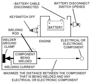
Illustration 1 |
|
g01143634 |
|
Components for the driven equipment should also be considered. When possible, remove the component that requires welding. When welding on an engine that is equipped with an ECM and removal of the component is not possible, the following procedure must be followed. This procedure minimizes the risk to the electronic components. |
|
Service welding guide (typical diagram) |
|
5. When possible, connect the ground clamp for the welding equipment directly to the engine |
|
component that will be welded. Place the clamp as close as possible to the weld. Close positioning reduces the risk of welding current damage to the engine bearings, to the electrical components, and to other components. |
|
1. Stop the engine. Remove the electrical power from the ECM. |
|
2. Ensure that the fuel supply to the engine is turned off. |
|
6. Protect the wiring harnesses from welding debris |
|
and/or from welding spatter. |
|
3. Disconnect the negative battery cable from the battery. If a battery disconnect switch is installed, open the switch. |
|
7. Use standard welding procedures to weld the materials together. |
|
4. Disconnect all electronic components from the wiring harnesses. Include the following components: |
|
i05513196 |
|
System Overview |
|
• Electronic components for the driven equipment |
|
The engine has an electronic control system. The system controls the engine. |
|
• ECM |
|
• Sensors |
|
The control system consists of the following components: |
|
• Electronically controlled valves • Relays |
|
• Electronic Control Module (ECM) • Software (flash file) • Wiring |
|
NOTICE |
|
Do not use electrical components (ECM or ECM sen- sors) or electronic component grounding points for grounding the welder. |
|
• Sensors |
|
• Actuators |
|
The following information provides a general description of the control system. Refer to Systems Operation, Testing, and Adjusting for detailed information about the control system. This document has been printed from SPI2. NOT FOR RESALE. |
![]()
![]()
![]()
![]()
![]()
|
6 |
|
KENR8774 |
|
Electronic Troubleshooting |
|
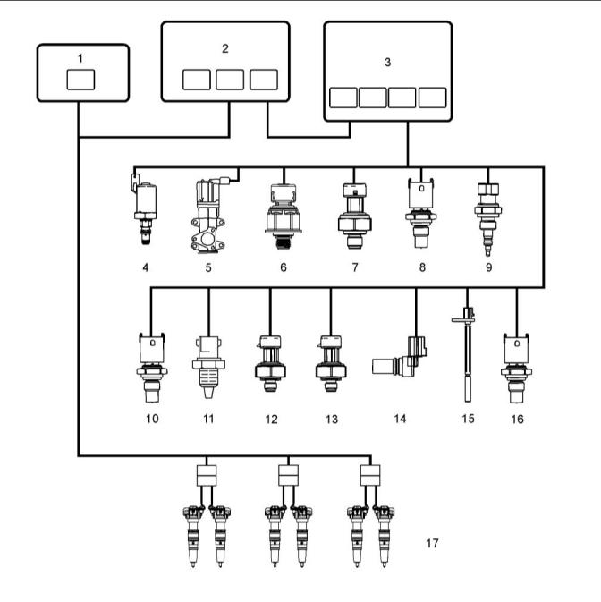
Electronic Control Circuit Diagram |
|
Illustration 2 |
|
g03383024 |
|
(1) Exhaust Gas Recirculation (EGR) control module (2) Injector drive module (IDM) (3) Electronic Control Module (ECM) (including internal barometric pressure sensor) |
|
(5) Exhaust Gas Recirculation (EGR) valve |
|
(11) Inlet Air Temperature sensor |
|
(6) Injection Control Pressure (ICP) sensor (7) Engine Fuel Pressure (EFP) sensor (8) Engine Coolant Temperature (ECT) sensor (9) Manifold Air Pressure (MAP) sensor (10) Manifold Air Temperature (MAT) sensor |
|
(12) Exhaust Back Pressure (EBP) sensor (13) Engine Oil Pressure (EOP) sensor (14) Camshaft Position (CMP) sensor (15) Crankshaft Position (CKP) sensor (16) Engine Oil Temperature (EOT) sensor (17) Fuel injectors |
|
(4) Injector Pressure Regulator (IPR) |
|
This document has been printed from SPI2. NOT FOR RESALE. |
![]()
![]()
|
KENR8774 |
|
7 |
|
Electronic Troubleshooting |
|
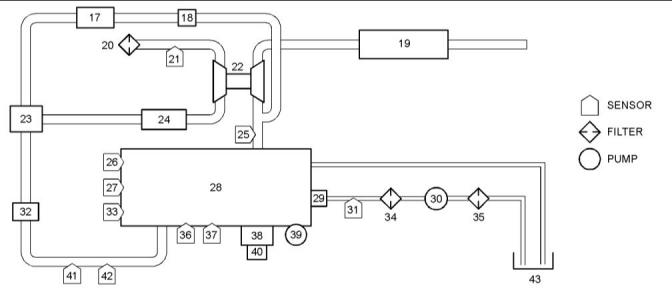
Block Diagram |
|
Illustration 3 |
|
g02276814 |
|
Block diagram for the 1600 engine |
|
(17) EGR cooler (18) EGR valve (19) Muffler (20) Air cleaner (21) Inlet Air Temperature(IAT) sensor (22) Turbocharger (23) EGR mixer (24) Charge Air Cooler (CAC) (25) Exhaust Back Pressure (EBP) sensor |
|
(26) Engine Coolant Temperature (ECT) sensor (27) Crankshaft Position (CKP) sensor (28) Engine |
|
(35) Fuel strainer |
|
(36) Injection Control Pressure (ICP) sensor (37) Engine Oil Pressure (EOP) sensor (38) Electronic control module (ECM) (39) High-pressureoil pump (40) Injector Drive Module (IDM) (41) Manifold Air Temperature (MAT) sensor (42) Manifold Air Pressure (MAP) sensor (43) Fuel tank |
|
(29) Injectors |
|
(30) Low-pressure fuel pump (31) Engine Fuel Pressure (EFP) sensor (32) Inlet Air Heater (IAH) (33) Camshaft Position (CMP) sensor (34) Fuel filter |
|
The Electronic Control Module (ECM) monitors and controls engine performance to ensure maximum performance and adherence to emissions standards. The ECM has four primary functions: |
|
values to determine the correct operating strategy for all engine operations. Diagnostic Trouble Codes (DTCs) are generated by the microprocessor, if inputs or conditions do not comply with expected values. |
|
• Provides reference voltage • Conditions input signals |
|
Diagnostic strategies are also programmed into the ECM. Some strategies monitor inputs continuously and command the necessary outputs to achieve the correct performance of the engine. |
|
• Processes and stores control strategies • Controls actuators |
|
Actuator control – The ECM controls the actuators by applying a low-level signal (low side driver) or a high-level signal (high side driver). When switched on, the drivers complete a ground or power circuit to an actuator. |
|
Reference Voltage – The ECM supplies a 5 VDC signal to input sensors in the electronic control system. By comparing the 5 VDC signal sent to the sensors with the respective returned signals, the ECM determines pressures, positions, and other variables important to engine functions. |
|
Act, , uators are controlled in three ways, determined by the type of actuator: |
|
Signal Conditioner – The signal conditioner in the internal microprocessor converts analog signals to digital signals, squares up sine wave signals, or amplifies low intensity signals to a level that the ECM microprocessor can process. |
|
• A duty cycle (percent time on/off) • A controlled pulse-width • Switched on or off |
|
Microprocessor – The ECM microprocessor stores operating instructions (control strategies) and value tables (calibration parameters). The ECM compares stored instructions and values with conditioned input |
|
This document has been printed from SPI2. NOT FOR RESALE. |
![]()
![]()
|
8 |
|
KENR8774 |
|
Electronic Troubleshooting |
|
Exhaust Gas Recirculation(EGR) Control Valve |
|
The ECM sends information (fuel volume, engine oil temperature, and injection control pressure) through the CAN 2 datalink to the IDM. The IDM uses this information to calculate the injection cycle. |
|
The EGR valve controls the flow of exhaust gases into the inlet and EGR mixer duct. |
|
Injector Power Source |
|
The EGR drive module controls the EGR actuator. |
|
The IDM creates a constant 48 VDC supply to all injectors by making and breaking a 12 VDC source across a coil in the IDM. The 48 VDC created by the collapsed field is stored in capacitors until used by the injectors. |
|
The EGR drive module receives the desired EGR actuator position from the ECM across the CAN 2 datalink to activate the valve for exhaust gas recirculation. The EGR drive module provides feedback to the ECM on the valve position. |
|
The IDM controls when the injector is turned on and how long the injector is active. The IDM first |
|
The EGR drive module constantly monitors the EGR actuator. When an EGR control error is detected, the EGR drive module sends a message to the ECM and a DTC is set. |
|
energizes the OPEN coil, then the CLOSE coil. The low side driver supplies a return circuit to the IDM for each injector coil (open and close). The high side driver controls the power supply to the injector. During each injection event, the low and high side drivers are switched on and off for each coil. |
|
Injection Pressure Regulator (IPR) |
|
The IPR valve controls pressure in the Injection Control Pressure (ICP) system. The IPR valve is a variable position valve controlled by the ECM. This regulated pressure actuates the fuel injectors. The valve position is controlled by switching the ground circuit in the ECM. The voltage source is supplied by the ignition switch. |
|
IDM and Injector Diagnostics |
|
The IDM determines if an injector is drawing enough current. The IDM sends a fault to the ECM, indicating potential problems in the wiring harness or injector, and the ECM will set a DTC. The IDM also does self- diagnostic checks and sets a DTC to indicate failure of the IDM. |
|
Inlet Air Heater (IAH) |
|
On-demand tests can be done using the Electronic Service Tool (EST). The ESTsends a request to the ECM and the ECM sends a request to the IDM to do a test. Some tests generate a DTC when a problem exists. Other tests require the technician to evaluate parameters, if a problem exists. |
|
The IAH system warms the incoming air supply prior to cranking to aid cold engine starting and reduce white smoke during warm-up. |
|
The ECM is programmed to energize the IAH elements through the IAH relays while monitoring certain programmed conditions for engine coolant temperature, engine oil temperature, and atmospheric pressure. |
|
Engine Sensors |
|
Temperature Sensors |
|
Injection Drive Module (IDM) |
|
A thermistor sensor changes electrical resistance with changes in temperature. Resistance in the thermistor decreases as temperature increases, and increases as temperature decreases. Thermistors work with a resistor that limits current in the ECM to form a voltage signal matched with a temperature value. |
|
The IDM has three functions: • Electronic distributor for injectors • Power source for injectors • IDM and injector diagnostics |
|
The top half of the voltage divider is the current limiting resistor inside the ECM. A thermistor sensor has two electrical connectors, signal return and ground. The output of a thermistor sensor is a nonlinear analog signal. |
|
The IDM distributes current to the injectors. The IDM controls fueling to the engine by sending high voltage pulses to the OPEN and CLOSE coils of the injector. The IDM uses information from the ECM to determine the timing and quantity of fuel for each injector. |
|
Engine Coolant Temperature (ECT) |
|
The ECM uses CKP sensor and CMP sensor input signals to calculate engine speed and position. The ECM conditions both input signals and supplies the IDM with the speed/timing sensor output signals. The IDM uses these signals to determine the correct sequence for injector firing. |
|
The ECM monitors the ECTsignal and uses this information for the instrument panel temperature gauge, coolant compensation, Engine Warning Protection System (EWPS), and inlet air heater operation. The ECT is a backup, if the engine oil temperature is out-of-range. The ECTsensor is installed in the water supply housing , right of the flat idler pulley assembly. |
|
This document has been printed from SPI2. NOT FOR RESALE. |
![]()
|
KENR8774 |
|
9 |
|
Electronic Troubleshooting |
|
Engine Oil Temperature (EOT) |
|
Exhaust Back Pressure (EBP) |
|
The ECM monitors the EOTsignal to control fuel quantity and timing when operating the engine. The EOTsignal allows the ECM and IDM to compensate for differences in oil viscosity for temperature changes. This compensation ensures that power and torque are available for all operating conditions. The EOTsensor is installed in the rear of the front cover, left of the high-pressure oil pump assembly. |
|
The EBP sensor measures exhaust back pressure so that the ECM can control the EGR system. The sensor provides feedback to the ECM for closed loop control of the Turbocharger. The EBP sensor is installed in a bracket mounted on the water supply housing. |
|
Engine Fuel Pressure (EFP) |
|
Intake Air Temperature (IAT) |
|
The ECM uses the EFP sensor signal to monitor engine fuel pressure and give an indication when the fuel filter needs to be changed. The EFP sensor is installed in the rear of the fuel filter assembly (crankcase side). |
|
The ECM monitors the IATsignal to control timing and fuel rate during cold starts. The IATsensor is mounted on the air filter housing. |
|
Manifold Air Temperature (MAT) |
|
Micro Strain Gauge Sensors |
|
The ECM monitors the MATsignal for EGR operation. The MATsensor is installed in the intake manifold. |
|
A micro strain gauge sensor measures pressure. Pressure to be measured exerts force on a pressure vessel that stretches and compresses to change resistance of strain gauges bonded to the surface of the pressure vessel. Internal sensor electronics convert the changes in resistance to a ratio metric voltage output. |
|
Variable capacitance sensor |
|
Variable capacitance sensors measure pressure. The pressure measured is applied to a ceramic material. The pressure forces the ceramic material closer to a thin metal disk. This action changes the capacitance of the sensor. |
|
The sensor is connected to the ECM by three wires: • 5 VDC supply |
|
The sensor is connected to the ECM by three wires: • 5 VDC supply |
|
• Signal return |
|
• Signal ground |
|
• Signal return |
|
The sensor receives the 5 VDC supply and returns an analog signal voltage to the ECM. The ECM compares the voltage with pre-programmed values to determine pressure. |
|
• Signal ground |
|
The sensor receives the 5 VDC and returns an analog signal voltage to the ECM. The ECM compares the voltage with pre-programmed values to determine pressure. |
|
Injection Control Pressure (ICP) |
|
The ECM monitors the ICP signal to determine the injection control pressure for engine operation. The ICP signal is used to control the IPR valve. The ICP sensor provides feedback to the ECM for Closed Loop ICP control. The ICP sensor is under the valve cover, forward of the No. 6 fuel injector in the high- pressure oil rail. |
|
Barometric Absolute Pressure (BAP) |
|
The ECM monitors the BAP signal to determine altitude, adjust timing, fuel quantity, and inlet air heater operation. |
|
Intake Manifold Air Pressure (MAP) |
|
Magnetic Pickup Sensors |
|
The ECM monitors the MAP signal to determine intake manifold pressure (boost). This information is used to control fuel rate and injection timing. The MAP sensor is installed left of the MATsensor in the intake manifold. |
|
A magnetic pickup sensor generates an alternating frequency that indicates speed. Magnetic pickups have a two wire connection for signal and ground. This sensor has a permanent magnetic core surrounded by a wire coil. The signal frequency is generated by the rotation of gear teeth that disturb the magnetic field. |
|
Engine Oil Pressure (EOP) |
|
The ECM monitors the EOP signal, and uses this information for the instrument panel pressure gauge and EWPS. The EOP sensor is installed in the left side of the crankcase below and left of the fuel filter housing. |
|
This document has been printed from SPI2. NOT FOR RESALE. |