 English
 Espaol
 Franais
 阿拉伯
阿拉伯 中文
中文 Deutsch
 Italiano
 Português
 日本
日本 韩国
韩国 български
 hrvatski
 esky
esky Dansk
Dansk Nederlands
 suomi
suomi Ελληνικ
 印度
印度 norsk
norsk Polski
 Roman
Roman русский
 Svenska
Perkins珀金斯1600柴油发动机7078366 C91油底壳/垫片供应商,Perkins珀金斯1600柴油发动机7078366 C91油底壳/垫片技术价格规格咨询服务,Perkins珀金斯1600柴油发动机7078366 C91油底壳/垫片零配件供应,Perkins珀金斯1600柴油发动机7078366 C91油底壳/垫片售后服务中心,Perkins珀金斯1600柴油发动机7078366 C91油底壳/垫片,Perkins珀金斯1600柴油发动机7078366 C91油底壳/垫片详细的技术参数,

产品中心
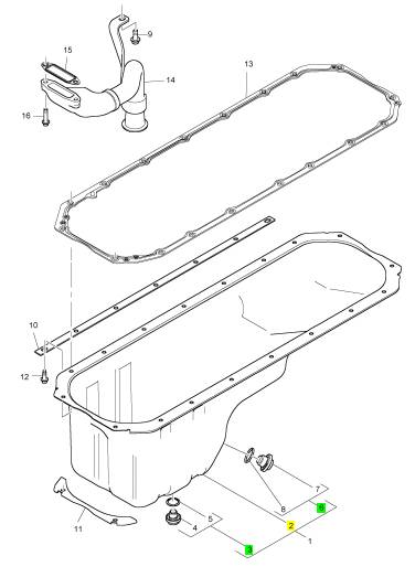
Perkins珀金斯1600柴油发动机7078366 C91油底壳/垫片
详细描述
项目 零配件号码 新件号 描述
1 7078366 C91 1 7078366 C91 油底壳
9 1817965 C1 1 1817965 C1 螺拴
10 1840135 C2 2 1840135 C2 托架
11 1840136 C1 2 1840136 C1 托架
12 1823281 C1 18 1823281 C1 螺拴
13 1836197 C1 1 1836197 C1 密封垫片 -油底壳
14 1843449 C2 1 1843449 C2 管 - 油的吸入
15 1841296 C1 1 1841296 C1 密封垫片 - 油的吸入管
16 1817978 C1 2 1817978 C1 螺拴
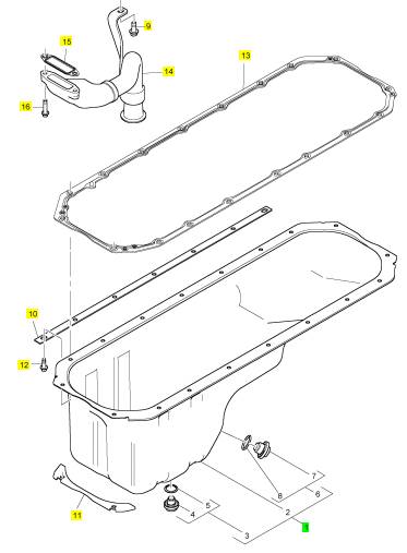
项目 零配件号码 新件号 描述
2 1 油底壳
3 1871904 C91 1 1871904 C91 排泄栓塞
6 1872269 C91 1 1872269 C91 排泄栓塞
|
Electronic Troubleshooting |
|
Crankshaft Position (CKP) sensor |
|
Event Codes |
|
Event Codes are used to indicate that the ECM has detected an abnormal engine operating condition. The ECM will log the occurrence of the event code. An event code does not indicate an electrical malfunction or an electronic malfunction. For example, if the temperature of the coolant in the engine is higher than the permitted limit, then the ECM will detect the condition. The ECM will then log an event code for the condition. |
|
The CKP sensor provides the ECM with a signal that indicates crankshaft speed and position. As the crankshaft turns, the CKP sensor detects a 60 tooth timing disk on the crankshaft. Teeth 59 and 60 are missing. By comparing the crankshaft signal with the camshaft signal, the ECM calculates engine rpm and timing requirements. The CKP sensor is installed in the top left side of the flywheel housing. |
|
Camshaft Position (CMP) sensor |
|
Engine Warning Protection System (EWPS) |
|
The CMP sensor provides the ECM with a signal that indicates camshaft position. As the cam rotates, the sensor identifies the position of the cam by locating a peg on the cam. The CMP is installed in the front cover, above and to the left of the water pump pulley. |
|
The EWPS safeguards the engine from undesirable operating conditions to prevent engine damage and to prolong engine life. The ECM will illuminate the red ENGINE lamp when the ECM detects: |
|
Switches |
|
• High coolant temperature • Low oil pressure |
|
Switch sensors indicate position, level, or status. Switch sensors operate open or closed, allowing or preventing the flow of current. A switch sensor can be a voltage input switch or a grounding switch. A voltage input switch supplies the ECM with a voltage when closed. A grounding switch will ground the circuit when closed, causing a zero voltage signal. Grounding switches are usually installed in series with a current limiting resistor. |
|
• Low coolant level |
|
When the protection feature is enabled and a critical engine condition occurs, the on-board electronics will shut down the engine. An event logging feature will record the event in engine hours. After the engine has shutdown, and the critical condition remains, the engine can be started for a 30 second run time. |
|
Water In Fuel (WIF) |
|
i05510289 |
|
A Water In Fuel (WIF) switch in the element cavity of the fuel filter housing detects water. When enough water accumulates in the element cavity, the WIF sensor signal changes to the Electronic Control Module (ECM). The ECM sends a message to illuminate the amber water and fuel lamp, alerting the operator. The WIF is installed in the base of the fuel filter housing. |
|
Glossary |
|
Actuator – A device that performs work in response to an input signal. |
|
Aeration – The entrapment of gas (air or combustion |
|
gas) in the coolant, lubricant, or fuel. |
|
Diagnostic Trouble Codes (DTC) |
|
After cooler (Charge Air Cooler) – A heat exchanger mounted in the charge air path between the turbocharger and engine intake manifold. The after cooler reduces the charge air temperature by transferring heat from the charge air to a cooling medium (usually air). |
|
Diagnostic Codes |
|
When the ECM detects an electronic system fault, the ECM generates a diagnostic code. Also, the ECM logs the diagnostic code in order to indicate the time of the occurrence. The ECM also logs the number of occurrences of the fault. Diagnostic codes are provided in order to indicate that the ECM has detected an electrical fault or an electronic fault with the engine control system. In some cases, the engine performance can be affected when the condition that is causing the code exists. |
|
Air Management System (AMS) – The AMS controls and directs air through the intake and exhaust which affects engine performance and controls emissions. |
|
Alternating Current (AC) – An electric current that reverses direction at regularly recurring intervals. |
|
If the operator indicates that a performance issue occurs, the diagnostic code may indicate the cause of the issue. Use the electronic service tool to access the diagnostic codes. Any fault should then be corrected. |
|
Ambient temperature – The environmental air temperature in which a unit is operating. In general, the temperature is measured in the shade (no solar radiation) and represents the air temperature for other engine cooling performance measurement purposes. Air entering the radiator may or may not be the same ambient due to possible heating from other sources or recirculation. |
|
This document has been printed from SPI2. NOT FOR RESALE. |
![]()
|
KENR8774 |
|
11 |
|
Electronic Troubleshooting |
|
Ampere (amp) – The standard unit for measuring the strength of an electrical current. The flow rate of a charge in a conductor or conducting medium of 1 coulomb per second. |
|
Crankshaft (CKP) sensor – The CKP sensor is a magnetic pickup sensor that indicates crankshaft speed and position. |
|
Current – The flow of electrons passing through a |
|
Analog – A continuously variable voltage. |
|
conductor. Measured in amperes. |
|
American Trucking Association (ATA) Data link – A serial data link specified by the American Trucking Association and the SAE. |
|
Damper – A device that reduces the amplitude of torsional vibration. |
|
Diagnostic Trouble Code (DTC) – Formerly called a Fault Code. A DTC is a three digit numeric code used for troubleshooting. |
|
Barometric Absolute Pressure (BAP) sensor – A variable capacitance sensor which, when supplied with a 5 V reference signal from the ECM, produces a linear analog voltage signal indicating atmospheric pressure. |
|
Direct Current (DC) – An electric current flowing in one direction only and substantially constant in value. |
|
Boost pressure – The pressure of the charge air leaving the turbocharger or inlet manifold pressure that is greater than atmospheric pressure. Obtained by turbocharging. |
|
Disable – A computer decision that deactivates a system and prevents operation of the system. |
|
Displacement – The stroke of the piston multiplied by the area of the cylinder bore multiplied by the number of cylinders in the engine. |
|
Bottom Dead Center (BDC) – The lowest position of |
|
the piston during the stroke. |
|
Electronic Control Module (ECM) – The Electronic Control Module is an electronic microprocessor that monitors and controls engine performance, exhaust emissions, and engine system performance. The ECM provides diagnostic information for engine systems and can be programmed at different levels for engine protection, warning, and shutdown. |
|
Calibration – The data values used by the strategy to solve equations and make decisions. Calibration values are stored in ROM and put into the processor during programming to allow the engine to operate within certain parameters. |
|
Camshaft Position (CMP) sensor – The CMP sensor is a magnetic pickup sensor which indicates engine position. Speed is indicated by the number of vanes counted per revolution of the camshaft. Camshaft position is indicated by a single position peg that indicates Cylinder Number 1. |
|
Engine Control Module (ECM) power relay – An ECM controlled relay that supplies power to the ECM. |
|
Electronic Service Tool (EST) – A computer diagnostic and programming tool for the ECM. The hardware is typically a laptop computer or notebook computer. |
|
Charge air – Dense, pressurized, heated air |
|
discharged from the turbocharger. |
|
Engine Coolant Temperature (ECT) sensor – A thermistor sensor that senses engine coolant temperature. |
|
Closed crankcase – Crankcase ventilation system that recycles crankcase gases through a breather, then back to the clean air intake. |
|
Engine Fuel Pressure (EFP) sensor – A variable |
|
Closed loop operation – A system that uses a sensor to provide feedback to the ECM. The ECM uses the sensor to continuously monitor variables and make adjustments in order to match engine requirements. |
|
capacitance sensor that senses fuel pressure. |
|
Engine Family Rating Code (EFRC) – A readable code in the calibration list of the EST that identifies engine horsepower and emission calibrations. |
|
Engine OFF tests – Tests that are done with the ignition key ON and the engine OFF. |
|
Continuous Monitor Test – An ECM function that continuously monitors the inputs and outputs to ensure that readings are within set limits. |
|
Engine RUNNING tests – Tests done with the engine |
|
running. |
|
Controller Area Network (CAN) – A J1939 high speed communication link. CAN 1 is a public data link between other modules and the ECM. CAN 2 is a private link between the ECM and IDM. |
|
Engine Oil Pressure (EOP) sensor – A variable capacitance sensor that senses engine oil pressure. |
|
Engine Oil Temperature (EOT) sensor – A thermistor sensor that senses engine oil temperature. |
|
Coolant – A fluid used to transport heat from one point to another. |
|
Exhaust Gas Recirculation (EGR) – The Exhaust Gas Recirculation is a system that recycles a controlled portion of exhaust gas back into the combustion chamber to reduce Nitrogen Oxide exhaust emissions. |
|
Crankcase – The housing that encloses the crankshaft, connecting rods, and allied parts. |
|
Crankcase breather – A vent for the crankcase to release excess interior air pressure. |
|
Crankcase pressure – The force of air inside the crankcase against the crankcase housing. |
|
Exhaust Gas Recirculation (EGR) drive module – The EGR drive module controls the position of the EGR valve. |
|
This document has been printed from SPI2. NOT FOR RESALE. |
![]()
|
12 |
|
KENR8774 |
|
Electronic Troubleshooting |
|
Exhaust Gas Recirculation (EGR) cooler – The exhaust gas is cooled in the EGR cooler and flows through the EGR control valve to the EGR mixer duct. |
|
Injection Control Pressure (ICP) sensor – A variable capacitance sensor that senses injection control pressure. |
|
Exhaust Gas Recirculation (EGR) valve – The EGR valve, when open, will mix exhaust gas with filtered intake air which flows into the intake manifold. The EGR valve, when closed, only allows filtered air to flow into the intake manifold. |
|
Injector Drive Module (IDM) power relay – An IDM controlled relay that supplies power to the IDM. |
|
Intake Air Temperature (IAT) sensor – A thermistor sensor that senses intake air temperature. |
|
Intake manifold – A plenum through which the air mixture flows from the charged air cooler piping to the intake passages of the cylinder head. |
|
Exhaust manifold – Exhaust gases flow through the exhaust manifold to the turbocharger exhaust inlet and are directed to the EGR cooler or out the exhaust system. |
|
Intake Manifold Air Pressure Sensor (MAP) – The Intake Manifold Pressure Sensor measures the pressure in the intake manifold. The pressure in the intake manifold may be different to the pressure outside the engine (atmospheric pressure). The difference in pressure may be caused by an increase in air pressure by a turbocharger. |
|
Fault detection and management – An alternate control strategy that reduces adverse effects that can be caused by a system failure. If a sensor fails, the ECM substitutes a good sensor signal or assumed sensor value. |
|
Filter restriction – A blockage, usually from contaminants, that prevents the flow of fluid through a filter. |
|
Intake Manifold Air Temperature Sensor (MAT) – A thermistor style sensor housed in the intake manifold used to indicate air temperature after passing through the charge air cooler. |
|
Flash File – This file is software that is inside the ECM. The file contains all the instructions (software) for the ECM and the file contains the performance maps for a specific engine. The file may be |
|
J1939 CAN Data Links – These data links are SAE standard diagnostic communications data links that are used to communicate between the ECM and other electronic devices. |
|
reprogrammed through flash programming. |
|
Flash Programming – Flash programming is the method of programming or updating an ECM with an electronic service tool over the data link instead of replacing components. |
|
Logged Diagnostic Codes – Logged diagnostic codes are codes which are stored in the memory. These codes are an indicator of possible causes for intermittent problems. Refer to the term “Diagnostic Trouble Codes” for more information. |
|
Fuel inlet restriction – A blockage, usually from contaminants, that prevents the flow of fluid through the fuel inlet line. |
|
Lubricity – Lubricity is the ability of a substance to reduce friction between solid surfaces in relative motion under loaded conditions. |
|
Fuel pressure – The force that the fuel exerts on the |
|
fuel system as it is pumped through the fuel system. |
|
Microprocessor – An integrated circuit in a |
|
Fuel strainer – A pre-filter in the fuel system that keeps larger contaminants from entering the fuel system. |
|
microcomputer that controls information flow. |
|
Nitrogen Oxides (NOx) – Nitrogen oxides form by a reaction between nitrogen and oxygen at high temperatures and pressures in the combustion chamber. |
|
Hall effect – The development of a transverse electric potential gradient in a current-carrying conductor or semiconductor when a magnetic field is applied. |
|
Normally closed – Refers to a switch that remains closed when no control force is acting on it. |
|
Hall effect sensor – Generates a digital on or off signal that indicates speed or position. |
|
Normally open – Refers to a switch that remains open when no control force is acting on it. |
|
Harness – The harness is the bundle of wiring (loom) that connects all components of the electronic system. |
|
Ohm (Ω) – The unit of resistance. 1 ohm is the value of resistance through which a potential of 1 V will maintain a current of 1 ampere. |
|
Hertz (Hz) – Hertz is the measure of electrical frequency in cycles per second. |
|
On-demand test – A self test that the technician initiates using the EST. It is run from a program in the processor. |
|
Injection Pressure Regulator (IPR) – A PulseWidth Modulated (PWM) regulator valve, controlled by the ECM, that regulates injection control pressure. |
|
Open Circuit – An open circuit is a condition that is caused by an open switch, or by an electrical wire or a connection that is broken. When this condition exists, the signal or the supply voltage can no longer reach the intended destination. |
|
Injection Control Pressure (ICP) – High lube oil pressure generated by a high-pressure pump/ pressure regulator used to hydraulically actuate the fuel injectors. |
|
Output Circuit Check (OCC) – An On-demand test done during an Engine OFF self test to check the continuity of selected actuators. |
|
This document has been printed from SPI2. NOT FOR RESALE. |
![]()
|
KENR8774 |
|
13 |
|
Electronic Troubleshooting |
|
Supply Voltage – The supply voltage is a continuous voltage that is supplied to a component. The power may be generated by the ECM or the power may be battery voltage that is supplied by the engine wiring. |
|
Output State Check (OSC) – An On-demand test that forces the processor to activate actuators (High or Low) for additional diagnostics. |
|
Parameter – A parameter is a value or a limit that is programmable. A parameter helps determine specific characteristics or behaviors of the engine. |
|
Switch sensors – Switch sensors indicate position. They operate open or closed, allowing or preventing the flow of current. A switch sensor can be a voltage input switch , or a grounding switch. A voltage input switch supplies the ECM with a voltage when it is closed. A grounding switch grounds the circuit closed, causing a zero voltage signal. Grounding switches are usually installed in series with a current limiting resistor. |
|
Particulate matter – Particulate matter includes mostly burned particles of fuel and engine oil. |
|
Potentiometer – A potentiometer is a variable voltage divider that senses the position of a mechanical component. A reference voltage is applied to one end of the potentiometer. Mechanical rotary or linear motion moves the wiper along the resistance material, changing voltage at each point along the resistive material. Voltage is proportional to the amount of mechanical movement. |
|
Top Dead Center (TDC) – The highest position of the piston during the stroke. |
|
Torque – Torque is a measure of force producing torsion and rotation around an axis. Torque is the product of the force, usually measured in pounds, and radius perpendicular to the axis of the force extending to the point where the force is applied or where it originates, usually measured in feet. |
|
Power Cycling – Power cycling refers to the action of cycling the keyswitch from any position to the OFF position, and to the START/RUN position. |
|
Pulse Width Modulation (PWM) – The time that an actuator, such as an injector, remains energized. |
|
Turbocharger – A turbine driven compressor mounted to the exhaust manifold. The turbocharger increases the pressure, temperature, and density of intake air to charge air. |
|
Random Access Memory (RAM) – Computer memory that stores information. Information can be written to and read from RAM. Input information (current engine speed or temperature) can be stored in RAM to be compared to values stored in Read Only Memory (ROM). All memory in RAM is lost when the ignition switch is turned off. |
|
Valve cover gasket – A valve cover gasket that contains the pass through electronic wiring harness connectors for the ICP sensor, and six fuel injectors. |
|
Variable capacitance sensor – A variable capacitance sensor is a sensor that measures pressure. The pressure measured is applied to a ceramic material. The pressure forces the ceramic material closer to a thin metal disk. This action changes the capacitance of the sensor. |
|
Read Only Memory (ROM) – Computer memory that stores permanent information for calibration tables and operating strategies. Permanently stored information in ROM cannot be changed or lost by turning the engine off or when ECM power is interrupted. |
|
Viscosity – The internal resistance to the flow of any fluid. |
|
Reference Voltage – Reference voltage is a regulated voltage that is supplied by the ECM to a sensor. The reference voltage is used by the sensor to generate a signal voltage. |
|
Volt (v) – A unit of electromotive force that will move a current of 1 ampere through a resistance of 1 Ohm. |
|
Voltage – Electrical potential expressed in volts. |
|
Voltage drop – Reduction in applied voltage from the current flowing through a circuit or portion of the circuit current multiplied by resistance. |
|
Relay – A relay is an electromechanical switch. A flow of electricity in one circuit is used to control the flow of electricity in another circuit. A small current or voltage is applied to a relay in order to switch a much larger current or voltage. |
|
Wastegate – The wastegate is a device in a turbocharged engine that controls the maximum boost pressure that is provided to the inlet manifold. |
|
Sensor – A sensor is a device that is used to detect the current value of pressure or temperature, or mechanical movement. The information that is detected is converted into an electrical signal. |
|
Water In Fuel (WIF) switch – The WIF switch detects water in the fuel. |
|
Short Circuit – A short circuit is a condition that has an electrical circuit that is inadvertently connected to an undesirable point. An example of a short circuit is a wire which rubs against a vehicle frame and this rubbing eventually wears off the wire insulation. Electrical contact with the frame is made and results in a short circuit. |
|
i05513169 |
|
Electronic Service Tools |
|
Perkins electronic service tools are designed to help the service technician: |
|
Signal – The signal is a voltage or a waveform that is used in order to transmit information typically from a sensor to the ECM. |
|
This document has been printed from SPI2. NOT FOR RESALE. |
![]()
|
14 |
|
KENR8774 |
|
Electronic Troubleshooting |
|
• Retrieve diagnostic codes. |
|
Connecting the Perkins 1306/1606 |
|
Diagnostic Software and the |
|
• Diagnose electrical problems. |
|
Communication Adapter 3 (CA3) |
|
Service Tools |
|
The following tools are used to diagnose electrical faults. |
|
Table 1 |
|
Required Service Tools |
|
Part Number 27610376 |
|
Description |
|
3-Way Adaptor Harness |
|
27610398 |
|
Under Valve Cover (UVC) Sensor Breakout Harness |
|
27610374 27610375 27610393 27610377 |
|
Actuator Breakout Harness |
|
500 Ohm Resistor Harness |
|
Pressure Sensor Breakout Harness Temperature Sensor Breakout Harness |
|
27610378 |
|
Relay Breakout Harness |
|
1306/1606 Perkins Diagnostic Tool |
|
The Perkins Electronic Service Tool can display the following information: |
|
• Status of all pressure sensors and temperature sensors |
|
• Active diagnostic codes and logged diagnostic codes |
|
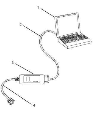
Illustration 4 |
|
g01121866 |
|
(1) Personal Computer (PC) |
|
• Logged events |
|
(2) Adapter Cable (Computer Serial Port) (3) Communication Adapter 3 (CA3) (4) Adapter Cable Assembly |
|
The Electronic Service Tool can also be used to perform diagnostic tests. |
|
Note: Items (2), (3) and (4) are part of the CA3 kit. |
|
Table 2 lists the service tools that are required in order to use the Electronic Service Tool. Table 2 |
|
Use the following procedure in order to connect the Perkins 1306/1606 Diagnostic Software and CA3. |
|
Service Tools for the Use of the Electronic Service Tool |
|
1. Turn the keyswitch to the OFF position. |
|
2. Connect cable (2) between the “COMPUTER” end of communication adapter (3) and the USB l port of PC (1). |
|
Part Number |
|
Description Single Use Program License Data Subscription for All Engines |
|
-(1) |
|
- (1) |
|
3. Connect cable (4) between the “DATA LINK” end of communication adapter (3) and the service tool connector. |
|
Communication Adapter (Electronic Service Tool to the ECM interface) |
|
27610401 |
|
(1) |
|
Refer to Perkins Engine Company Limited. |
|
4. Place the keyswitch in the ON position. |
|
Note: For more information on the Perkins 1306/ 1606 Diagnostic Software and the PC requirements, refer to the documentation that accompanies the Perkins 1306/1606 Diagnostic Software. |
|
This document has been printed from SPI2. NOT FOR RESALE. |


![]()
![]()
![]()
|
KENR8774 |
|
15 |
|
Electronic Troubleshooting |
|
Illustration 5 |
|
g03384803 |
|
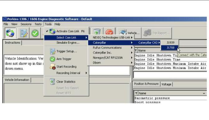
5. Select the correct data link. Refer to Illustration 5 |
|
Illustration 6 |
|
g03384841 |
|
6. Select the correct engine type. Refer to Illustration 6 . |
|
7. If the Perkins 1306/1606 Diagnostic Software and the communication adapter do not communicate with the Electronic Control Module (ECM), refer to the diagnostic procedure Troubleshooting, |
|
“Electronic Service Tool Does Not Communicate”. |
|
This document has been printed from SPI2. NOT FOR RESALE. |
![]()

![]()
![]()
|
16 |
|
KENR8774 |
|
Electronic Troubleshooting |
|
Perkins 1306/1606 Diagnostic Software Functions |
|
Optional Engine Events |
|
Optional engine events are monitored and recorded, if the engine is equipped with the optional Engine Warning Protection System (EWPS). Optional engine events recorded by the ECM include low coolant level and low oil pressure. |
|
Continuous Monitor |
|
Continuous Monitor is a series of continuous diagnostic tests done by the Electronic Control Module (ECM) to detect failure modes (Out of Range, In Range, and System Faults). During Continuous Monitor the ignition switch is on. |
|
Engine Event Hours |
|
The ECM records engine events in hours . |
|
• Out of Range High (Voltage over normal operating range) |
|
The ECM stores the two most recent events. Two events could happen in the same hour, and two events could happen in the same mile. |
|
• Out of Range Low (Voltage under normal operating range) |
|
Diagnostic Trouble Codes (DTCs) |
|
• In Range (In normal operating range but not correct for conditions) |
|
Type - Indicates active or inactive DTCs. |
|
• System Malfunction (System is not operating according to conditions) |
|
Active – With the ignition switch in the ON position, active indicates a DTC for a condition currently in the system. When the ignition switch is turned off, an active DTC becomes inactive. (If a problem remains, the DTC will be active on the next ignition switch cycle and the Perkins 1306/1606 Diagnostic Software will display active/inactive.) |
|
If an input signal is out of range (over or under normal operating range), the ECM logs a fault and sets a Diagnostic Trouble Code (DTC). The ECM monitors the operation of systems for in range conditions to determine if systems are working in a normal operational range. If the ECM detects that a system falls outside a predetermined range, a fault will be logged and a DTC will be set. |
|
Inactive – With the ignition switch in the ON position, inactive indicates a DTC for a condition during a previous ignition switch cycle. When the ignition switch is turned to OFF, inactive DTCs from previous ignition switch cycles remain in the ECM memory until cleared. |
|
Each DTC has a three-digit number to identify the source of a malfunction measured or monitored electronically. A fault is a malfunction measured or monitored electronically. |
|
Active/Inactive – With the ignition switch in the ON position, active/inactive indicates a DTC for a condition currently in the system and was present in a previous ignition switch cycle, if the code was not cleared. |
|
The ECM continuously monitors the Injection Control Pressure (ICP) system and the Air Management System (AMS). If the ECM detects that a system falls outside a predetermined range, the ECM logs a fault and sets a DTC. |
|
Description - Defines each DTC |
|
During normal engine operation, the ECM |
|
automatically performs several tests to detect faults. |
|
Diagnostic Tests |
|
When a fault is detected, the ECM often runs a fault management strategy to allow continued, though sometimes degraded, engine operation. |
|
Perkins 1306/1606 Diagnostic Software is required to perform the following tests. |
|
With the engine running, engine events are permanently recorded in the ECM. Engine events can be retrieved with the Perkins 1306/1606 Diagnostic Software. |
|
Key-On Engine-Off (KOEO) Tests Standard Test |
|
The KOEO Standard test is done by the ECM. The technician runs this test, using the EST. |
|
Engine Events |
|
During the KOEO Standard test, the ECM does an internal test of the processing components and memory followed by an Output Circuit Check (OCC). The OCC evaluates the electrical condition of the circuits, not mechanical or hydraulic performance of the systems. By operating the ECM output circuits and measuring each response, the Standard test detects shorts or opens in the harnesses, actuators, and ECM. If a circuit fails the test, a fault is logged and a DTC is set. |
|
Standard Engine Events |
|
Standard engine events include excessive coolant temperature and engine rpm (over-speed). |
|
This document has been printed from SPI2. NOT FOR RESALE. |