 English
 Espaol
 Franais
 阿拉伯
阿拉伯 中文
中文 Deutsch
 Italiano
 Português
 日本
日本 韩国
韩国 български
 hrvatski
 esky
esky Dansk
Dansk Nederlands
 suomi
suomi Ελληνικ
 印度
印度 norsk
norsk Polski
 Roman
Roman русский
 Svenska
Perkins珀金斯1600柴油发动机1891415 C92正时齿轮供应商,Perkins珀金斯1600柴油发动机1891415 C92正时齿轮技术价格规格咨询服务,Perkins珀金斯1600柴油发动机1891415 C92正时齿轮零配件供应,Perkins珀金斯1600柴油发动机1891415 C92正时齿轮售后服务中心,Perkins珀金斯1600柴油发动机1891415 C92正时齿轮,Perkins珀金斯1600柴油发动机1891415 C92正时齿轮详细的技术参数,

产品中心
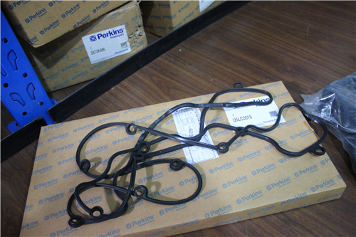
Perkins珀金斯1600柴油发动机1891415 C92正时齿轮
详细描述
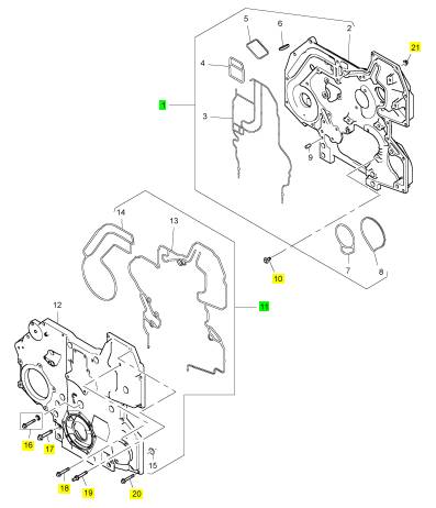
项目 零配件号码 新件号 描述
1 1891415 C92 1 1891415 C92 正时齿轮盖
10 1822121 C2 8 1822121 C2 公制的螺拴
11 1881727 C93 1 1881727 C93 正时齿轮盖
16 1873599 C91 1 1873599 C91 密封
17 1817960 C1 9 1817960 C1 公制的螺拴
18 1854752 C1 1 1854752 C1 螺拴
19 1874852 C2 2 1874852 C2 螺拴
20 1842857 C1 6 1842857 C1 螺拴
21 40050 R1 11 40050 R1 螺帽
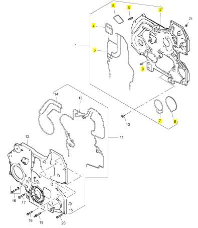
项目 零配件号码 新件号 描述
2 1 盖
3 1841016 C1 1 1841016 C1 密封 - 正时齿轮箱盖
4 1841017 C1 1 1841017 C1 密封 - 正时齿轮箱盖
5 1836243 C1 1 1836243 C1 密封 - 正时齿轮箱盖
6 1831027 C1 1 1831027 C1 栓塞
7 1836005 C1 1 1836005 C1 密封 - 正时齿轮箱盖
8 1836235 C1 1 1836235 C1 密封 - 正时齿轮箱盖
9 1820813 C1 4 1820813 C1 合钉
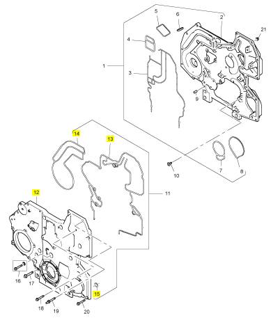
项目 零配件号码 新件号 描述
12 1 正时齿轮盖
13 1841018 C2 1 1841018 C2 密封 - 正时齿轮箱盖
14 1841019 C1 1 1841019 C1 密封 - 正时齿轮箱盖
15 1818402 C2 4 1818402 C2 密封O型圈
|
ENR8774 |
|
17 |
|
Electronic Troubleshooting |
|
The ECM checks the Injection pressure regulator circuit. |
|
• Barometric Absolute Pressure (BAP) |
|
• Battery Voltage |
|
When the OCC is done, the DTC window will display DTCs, if there are problems. |
|
• EGR Valve Position |
|
Note: When using the EST to do KOEO or Key-On Engine-Running (KOER) diagnostic tests, Standard test is always selected and run first. If the ignition switch is not cycled, do not run the Standard Test again. |
|
• Exhaust Back Pressure (EBP) • Engine Coolant Level (ECL) • Engine Fuel Pressure (EFP) (optional) • Engine Oil Pressure (EOP) • Engine Oil Temperature (EOT) • Intake Air Temperature (IAT) • Injection Control Pressure (ICP) • Manifold Air Temperature (MAT) • Manifold Absolute Pressure (MAP) |
|
Injector Test |
|
Note: The Standard test must be done before doing the Injector test. The Injector test diagnoses electrical problems in IDM wiring or injectors. |
|
Note: Before doing the Injector test, DTCs should be accessed, noted, and cleared. DTCs found will then be displayed as Active DTCs. |
|
During the Injector test, the ECM requests the IDM actuate the injectors in numerical order (1 through 6), not in ring order. The IDM monitors the electrical circuit for each injector, evaluates the performance of the injector coils, and checks the operation of the electrical circuit. If an electronic component in the injector drive circuit fails the expected parameters, the IDM sends a fault to the ECM. The ECM logs the fault, a DTC is set and sent to the EST. |
|
Output State Low Test |
|
The Output State Low test allows the technician to diagnose the operation of the output signals and actuators. |
|
In the Output State Low test mode, the ECM pulls down the output voltage to the low state. This grounds the low side driver circuits and actuates the output components controlled by the ECM. |
|
Note: The technician can monitor injector operation by listening to the sound of each injector when activated by the IDM. During Hard Start and No Start conditions, when oil is cold and thick, injectors may be hard to hear. |
|
During Output State Low test, the output of the circuit in question can be monitored with a Digital Multimeter (DMM). The DMM measures a low voltage state as the outputs are toggled. The actual voltage will vary with the circuit tested. |
|
The DTC window will display DTCs, if there are problems. |
|
Note: A breakout harness and a DMM are required to monitor the suspected circuit or actuator. DTCs are not set by the ECM during this test. |
|
Continuous Monitor Test |
|
The Continuous Monitor test troubleshoots intermittent connections between the ECM and sensors. The engine can be off or running. |
|
The following actuators are activated when toggled low during the test: |
|
• Injection Pressure Regulator (IPR) (electrical circuit only) |
|
The EST monitors the following circuits: |
|
• EGR (audible and visual inspection only) continuous monitoring by EGR drive module |
|
Glow Plug/Inlet Air Heater Output State Test |
|
The Glow Plug/Inlet Air Heater Output State test allows the technician to determine if the Inlet Air Heater System is operating correctly. |
|
The inlet air heater relay operation is activated for 30 seconds. A DMM and current clamp are used to measure the time the relay is on and the amperage that is drawn for the inlet air heater. |
|
This document has been printed from SPI2. NOT FOR RESALE. |
![]()
|
18 |
|
KENR8774 |
|
Electronic Troubleshooting |
|
Key-On Engine-Running(KOER) Tests Standard Test |
|
When all cylinders are active, the contribution of each cylinder is 17% of the overall effect to maintain governed speed. When three cylinders are shut off, contribution of each remaining cylinder is 33% of the overall effect to maintain governed speed. The technician should monitor fuel rate and engine load. |
|
During the KOER Standard test, the ECM commands the IPR through a step test to determine if the ICP system is performing as expected. The ECM monitors signal values from the ICP sensor and compares those values to the expected values. When the Standard test is done, the ECM returns the engine to normal operation and transmits DTCs set during the test. |
|
Note: The Relative Compression test should be done after doing the Injector Disable test to distinguish between an injector or mechanical problem. |
|
Note: Before running the manual or automatic injector disable test, ensure that the following conditions are met: |
|
Note: Before doing this test, confirm the following |
|
conditions: |
|
• Make sure that accessories are turned off. Items cycled during this test could corrupt the test results. |
|
• Problems causing active DTCs were corrected, and active DTCs were cleared. |
|
• Keep engine oil temperature within a 2° C (5° F) range from the beginning to the end of the test. Engine oil temperature affects injection timing. Too much of a change in engine oil temperature could corrupt the test results. |
|
• Engine coolant temperature must be at least 70° C (158° F)70 °C (158 °F). |
|
• Battery voltage must be higher than 10.5 VDC. |
|
Continuous Monitor Test |
|
Note: If any injectors are removed and reinstalled or replaced, run the engine for 30 minutes before checking for misfire or rough idle. |
|
The Continuous Monitor test troubleshoots intermittent connections at sensors and actuators. The engine can be off or running. |
|
Automatic Test |
|
The EST monitors the following circuits: • Barometric Absolute Pressure (BAP) • Battery Voltage |
|
The Automatic test is used when comparing cylinder to cylinder test data. |
|
Note: Do KOER Standard test before doing this test. |
|
• Exhaust Back Pressure (EBP) • Engine Coolant Level (ECL) • Engine Fuel Pressure (EFP) (optional) • Engine Oil Pressure (EOP) |
|
Manual Test - Engine Cold |
|
The Manual test is used when diagnosing each cylinder for cold misfire, considering engine oil temperature changes. |
|
The engine oil temperature indicator will change from red to green when engine temperature reaches 70° C (158° F) or higher. |
|
• Engine Oil Temperature (EOT) • Intake Air Temperature (IAT) • Injection Control Pressure (ICP) • Manifold Air Temperature (MAT) • Manifold Absolute Pressure (MAP) |
|
If the engine oil temperature indicator is red, erroneous comparisons are likely from cylinder to cylinder. However, when diagnosing a cold misfire, a technician can listen to tone changes from cylinder- to-cylinder. |
|
When the engine oil temperature indicator is green and the engine temperature is 70° C (158° F) or higher, fuel rate and timing are more stable, meaning that comparisons from cylinder to cylinder are more accurate. Overall engine operation is more stable. |
|
Injector Disable Tests |
|
The Injector Disable tests allow the technician to shut off injectors to determine if a specific cylinder is contributing to engine performance. Injectors can be shut off one at a time, alternative cylinders at a time or alternative cylinders plus one. |
|
Shut off one injector at a time and listen for changes in exhaust tone. |
|
Note: If any injectors are removed and reinstalled or replaced, run the engine for 30 minutes before checking for misfire or rough idle. |
|
Alternate cylinders are every other cylinder in ring order. |
|
Firing order: 1-5-3-6-2-4 |
|
This document has been printed from SPI2. NOT FOR RESALE. |
![]()
|
KENR8774 |
|
19 |
|
Electronic Troubleshooting |
|
i05584049 |
|
If an input signal is out of range (over or under normal operating range), the ECM logs a fault and sets a Diagnostic Trouble Code (DTC). The ECM monitors the operation of systems for in range conditions to determine if systems are working in a normal operational range. If the ECM detects that a system falls outside a predetermined range, a fault will be logged and a DTC will be set. |
|
Replacing the ECM |
|
NOTICE Keep all parts clean from contaminants. |
|
Each DTC has a three-digit number to identify the source of a malfunction measured or monitored electronically. A fault is a malfunction measured or monitored electronically. |
|
Contaminants may cause rapid wear and shortened component life. |
|
The engine is equipped with an Electronic Control Module (ECM). The ECM contains no moving parts. Follow the troubleshooting procedures in this manual in order to be sure that replacing the ECM will correct the problem. Verify that the suspect ECM is the cause of the problem. |
|
The ECM continuously monitors the Injection Control Pressure (ICP) system and the Air Management System (AMS). If the ECM detects that a system falls outside a predetermined range, the ECM logs a fault and sets a DTC. |
|
During normal engine operation, the ECM automatically performs several tests to detect faults. |
|
Note: Ensure that the ECM is receiving power and that the ECM is properly grounded before replacement of the ECM is attempted. Refer to the schematic diagram. |
|
When a fault is detected, the ECM often runs a fault management strategy to allow continued, though sometimes degraded, engine operation. |
|
Note: When a new ECM is not available, an ECM can be used from an engine that is not in service. The ECM must have the same serial number suffix. Ensure that the replacement ECM and the part number for the flash file match the suspect ECM. Be sure to record the parameters from the replacement ECM. |
|
With the engine running, engine events are permanently recorded in the ECM. Engine events can be retrieved with the Perkins 1306/1606 Diagnostic Software. |
|
Diagnostic Trouble Code – When a fault in the electronic system is detected, the ECM generates a diagnostic trouble code. The diagnostic trouble code indicates the specific fault in the circuitry. |
|
NOTICE |
|
If the flash file and engine application are not matched, engine damage may result. |
|
Diagnostic codes can have three different states: |
|
Active – With the ignition switch in the ON position, active indicates a DTC for a condition currently in the system. When the ignition switch is turned off, an active DTC becomes inactive. (If a problem remains, the DTC will be active on the next ignition switch cycle and the Perkins 1306/1606 Diagnostic Software will display active/inactive.) |
|
A replacement ECM and IDM can be obtained with the flash file already installed or a blank ECM can be ordered. |
|
If a blank ECM or IDM is being installed, contact “PartsHelpdesk@Perkins.com ” for the correct flash file. To install the flash file, refer to Troubleshooting, “Flash Programming”. |
|
Inactive – With the ignition switch in the ON position, inactive indicates a DTC for a condition during a previous ignition switch cycle. When the ignition switch is turned to OFF, inactive DTCs from previous ignition switch cycles remain in the ECM memory until cleared. |
|
i05345689 |
|
Self-Diagnostics |
|
Active/Inactive – With the ignition switch in the ON position, active/inactive indicates a DTC for a condition currently in the system and was present in a previous ignition switch cycle, if the code was not cleared. |
|
The Electronic Control Module (ECM) can detect faults in the electronic system and with engine operation. |
|
When a fault is detected, a diagnostic trouble code is generated. An alarm may also be generated. |
|
Engine Events |
|
Standard Engine Events |
|
Standard engine events include excessive coolant temperature and engine rpm (over-speed). |
|
This document has been printed from SPI2. NOT FOR RESALE. |
![]()
![]()
![]()
![]()
![]()
|
20 |
|
KENR8774 |
|
Electronic Troubleshooting |
|
Optional Engine Events |
|
Optional engine events are monitored and recorded, if the engine is equipped with the optional Engine Warning Protection System (EWPS). Optional engine events recorded by the ECM include low coolant level and low oil pressure. |
|
Engine Event Hours |
|
The ECM records engine events in hours . |
|
The ECM stores the two most recent events. Two events could happen in the same hour, and two events could happen in the same mile. |
|
i05346137 |
|
Sensors and Electrical Connectors |
|
Sensor Locations for the Engine |
|
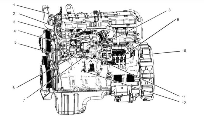
The illustrations in this section show the typical locations of the sensors for the industrial engine. Specific engines may appear different from the illustration due to differences in applications. |
|
Illustration 7 |
|
g02974017 |
|
Typical example |
|
(1) Exhaust Gas Recirculation (EGR) valve (2) Inlet air temperature sensor (3) Inlet manifold air pressure sensor (4) Water in fuel sensor |
|
(5) Engine oil temperaturesensor |
|
(9) Control module (10) Crankshaft position sensor (11) Coolant jacket heater |
|
(6) Injection pressure regulator (7) Engine fuel pressure sensor (8) Air inlet heater |
|
(12) Engine oil pressure sensor |
|
This document has been printed from SPI2. NOT FOR RESALE. |
![]()
![]()
|
KENR8774 |
|
21 |
|
Electronic Troubleshooting |
|
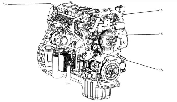
Illustration 8 |
|
g02976178 |
|
Typical example |
|
(13) Injection control pressure sensor (internal) |
|
(14) Exhaust back pressure sensor (15) Engine coolant temperature sensor |
|
(16) Camshaft position sensor |
|
This document has been printed from SPI2. NOT FOR RESALE. |
![]()
![]()
|
22 |
|
KENR8774 |
|
Electronic Troubleshooting |
|
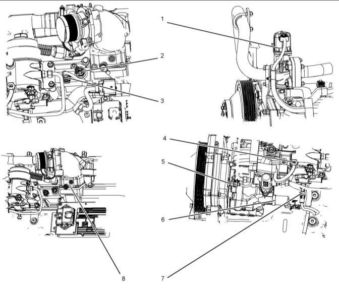
Illustration 9 |
|
g02732035 |
|
Typical example |
|
(1) EGR valve (2) Inlet air temperature sensor (3) Inlet manifold air pressure sensor |
|
(4) Water in fuel sensor (5) Engine oil temperaturesensor (6) Injection pressure regulator |
|
(7) Engine fuel pressure sensor (8) Inlet Air Heater (IAH) |
|
This document has been printed from SPI2. NOT FOR RESALE. |
![]()
![]()
|
KENR8774 |
|
23 |
|
Electronic Troubleshooting |
|
Illustration 10 |
|
g02732036 |
|
Typical example |
|
(9) Control module (A) EGR valve control module |
|
(B) Injection Drive Module (IDM) (C) IAH relay |
|
(D) Electronic Control Module (ECM) |
|
Illustration 11 |
|
g02976197 |
|
Typical example |
|
(10) Crankshaft position sensor |
|
(11) Coolant jacket heater |
|
(12) Engine oil pressure sensor |
|
This document has been printed from SPI2. NOT FOR RESALE. |