 English
 Espaol
 Franais
 阿拉伯
阿拉伯 中文
中文 Deutsch
 Italiano
 Português
 日本
日本 韩国
韩国 български
 hrvatski
 esky
esky Dansk
Dansk Nederlands
 suomi
suomi Ελληνικ
 印度
印度 norsk
norsk Polski
 Roman
Roman русский
 Svenska
Perkins珀金斯1600柴油发动机7076770 C1风扇轮廓供应商,Perkins珀金斯1600柴油发动机7076770 C1风扇轮廓技术价格规格咨询服务,Perkins珀金斯1600柴油发动机7076770 C1风扇轮廓零配件供应,Perkins珀金斯1600柴油发动机7076770 C1风扇轮廓售后服务中心,Perkins珀金斯1600柴油发动机7076770 C1风扇轮廓,Perkins珀金斯1600柴油发动机7076770 C1风扇轮廓详细的技术参数,

产品中心
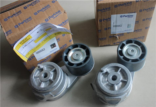
Perkins珀金斯1600柴油发动机7076770 C1风扇轮廓
详细描述
项目 零配件号码 新件号 描述
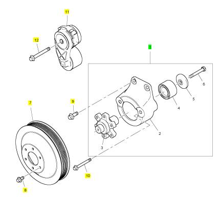
1 7076770 C1 1 7076770 C1 风扇轮廓总成
7 1850787 C2 1 1850787 C2 风扇皮皮带轮
8 1817812 C1 6 1817812 C1 公制的螺拴
9 1817956 C1 2 1817956 C1 公制的螺拴
10 1818230 C1 2 1818230 C1 公制的螺拴
11 1873217 C2 1 1873217 C2 张紧轮
12 1822018 C1 1 1822018 C1 公制的螺拴
项目 零配件号码 新件号 描述
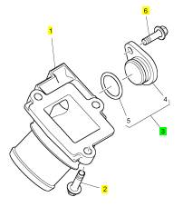
1 7081517 C2 1 7081517 C2 水肘管
1 7081517 C1 1 7081517 C2 水肘管
2 1817958 C1 3 1817958 C1 螺旋
3 1881730 C91 1 1881730 C91 栓塞
6 1817817 C1 1 1817817 C1 公制的螺拴
项目 零配件号码 新件号 描述
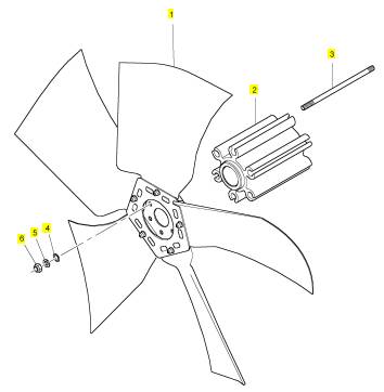
1 NS10092 1 NS10092 风扇
2 NS10093 1 NS10093 承接器
3 2121/24 6 2121/24 图钉
4 0730083 6 0730083 密封O型圈
5 2131 A008 6 2131 A008 垫圈
6 317411 6 317411 螺帽
|
This document has been printed from SPI2. NOT FOR RESALE. |
![]()
![]()
|
KENR8774 |
|
25 |
|
Electronic Troubleshooting |
|
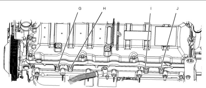
Illustration 13 |
|
g02976217 |
|
Typical example |
|
(G) Injection control pressure connection (H) Connector for injectors 1 and injector 2 |
|
(I) Connector for injectors 3 and injector 4 (J) Connector for injectors 5 and injector 6 |
|
This document has been printed from SPI2. NOT FOR RESALE. |
![]()
![]()
|
26 |
|
KENR8774 |
|
Electronic Troubleshooting |
|
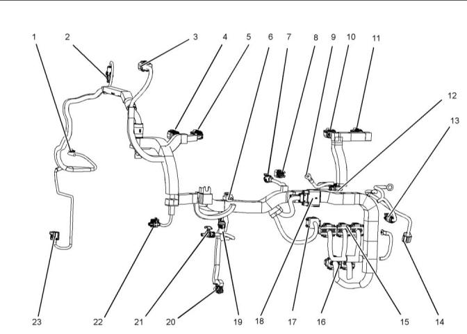
Wiring Harness |
|
Illustration 14 |
|
g02740876 |
|
(1) Coolant temperature (2) Exhaust back pressure (3) EGR valve (4) Injection control (5) Injectors 1 and 2 (6) Water in fuel |
|
(9) Inlet heater terminal (10) Injectors 3 and 4 (11) Injectors 5 and 6 (12) Plug for inlet heater (13) Relay (14) Crankshaft position (15) Injector drive connections (16) ECM |
|
(17) EGR control module (18) Customer connection (19) Low-pressure fuel (20) Engine oil pressure (21) Injection pressure regulator (22) Oil temperature |
|
(7) Inlet manifold air pressure (8) Inlet air temperature |
|
(23) Camshaft position connection |
|
This document has been printed from SPI2. NOT FOR RESALE. |
![]()
![]()
|
KENR8774 |
|
27 |
|
Electronic Troubleshooting |
|
i05513190 |
|
Engine Wiring |
|
Information |
|
|
|
Schematic Diagrams |
|
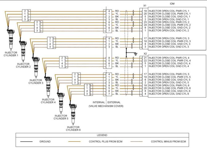
Illustration 15 |
|
g02212713 |
|
Schematic Diagram for the Injectors |
|
This document has been printed from SPI2. NOT FOR RESALE. |
![]()
![]()
|
28 |
|
KENR8774 |
|
Electronic Troubleshooting |
|
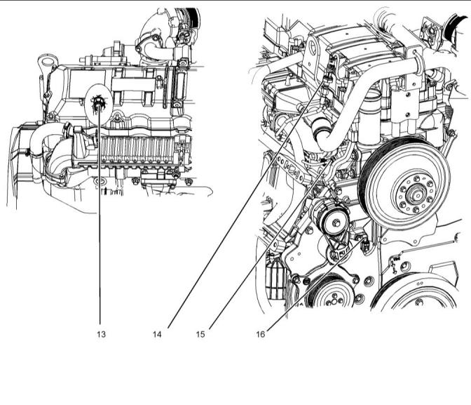
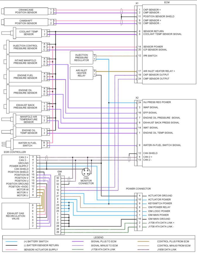
Illustration 16 |
|
g02216053 |
|
Schematic Diagram for the Engine |
|
This document has been printed from SPI2. NOT FOR RESALE. |
![]()
![]()
|
KENR8774 |
|
29 |
|
Electronic Troubleshooting |
|
Note: The EGR controller and EGR valve are applicable to the 1600D engine only. |
|
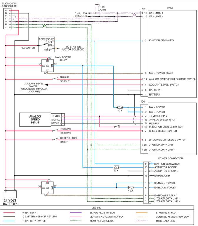
Illustration 17 |
|
g02223493 |
|
Schematic Diagram for a Typical Application |
|
This document has been printed from SPI2. NOT FOR RESALE. |
![]()
![]()
|
30 |
|
KENR8774 |
|
Electronic Troubleshooting |
|
i05352877 |
|
ECM Harness Connector Terminals |
|
|
|
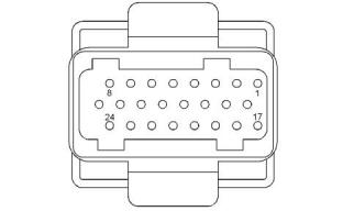
The Electronic Control Module (ECM) uses four connectors that have 24 terminals to interface to the wiring harness. |
|
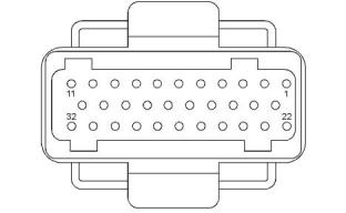
The Injector Driver Module (IDM) uses two connectors that have 24 terminals and one connector that has 32 terminals to interface to the wiring harness. |
|
Illustration 18 |
|
g03390396 |
|
Layout of the 24-pin connectors (view from the front) |
|
Illustration 19 |
|
g03390435 |
|
Layout of the 32-pin IDM connector (view from the front) |
|
This document has been printed from SPI2. NOT FOR RESALE. |
![]()
![]()
![]()
![]()
![]()
|
KENR8774 |
|
31 |
|
Programming Parameters |
|
Programming Parameters |
|
7. Turn the ignition keyswitch to the ON position and the OFF position when instructed to ensure that the flash file is saved. |
|
8. Only disconnect the 27610401 CA3 Communication Adaptor Kit from the ECM when the “Successfully Programmed” message appears. |
|
i05583509 |
|
Programming Parameters |
|
The electronic service tool can be used to view certain parameters that can affect the operation of the engine. The electronic service tool can also be used to change certain parameters. The parameters are stored in the Electronic Control Module (ECM). |
|
i05585209 |
|
Flash Programming |
|
Flash Programming – A method of loading a flash file into the Electronic Control Module (ECM) and the Injector Driver Module (IDM) |
|
Flash Programming a Flash File |
|
1. Contact “PartsHelpdesk@Perkins.com ” in order to obtain the correct flash file. The flash file will be sent via e-mail. |
|
2. Use a 27610404 Power-Up Harness to provide power to the ECM during the flash programming procedure. |
|
Note: If the 27610404 Power-Up Harness is not available, the ECM and IDM must be correctly connected to the batteries. The ECM must be able to control the main power relay and there must be a switch on the supply to ECM pin X3:3 and IDM pin X3:9. The main power to each module must be via relays that are switched by the modules. Refer to Troubleshooting, “Engine Wiring Information”. |
|
3. Connect the ECM to the computer using the 27610401 CA3 Communication Adaptor Kit. Refer to Troubleshooting, “Electronic Service Tools” for more information. |
|
4. Start the flash file program that was sent via e-mail. |
|
Note: The flash file is a self-contained executable file. No other software is required other than the CA3 Communication Adaptor drivers that are included with the 27610401 CA3 Communication Adaptor Kit. |
|
5. Select the “Perkins CA3” from the “Cables” drop- down box. |
|
6. Follow the on-screen instructions in order to install the flash file. |
|
This document has been printed from SPI2. NOT FOR RESALE. |