 English
 Espaol
 Franais
 阿拉伯
阿拉伯 中文
中文 Deutsch
 Italiano
 Português
 日本
日本 韩国
韩国 български
 hrvatski
 esky
esky Dansk
Dansk Nederlands
 suomi
suomi Ελληνικ
 印度
印度 norsk
norsk Polski
 Roman
Roman русский
 Svenska
Perkins珀金斯1600柴油发动机1842130 C3恒温节温器供应商,Perkins珀金斯1600柴油发动机1842130 C3恒温节温器技术价格规格咨询服务,Perkins珀金斯1600柴油发动机1842130 C3恒温节温器零配件供应,Perkins珀金斯1600柴油发动机1842130 C3恒温节温器售后服务中心,Perkins珀金斯1600柴油发动机1842130 C3恒温节温器,Perkins珀金斯1600柴油发动机1842130 C3恒温节温器详细的技术参数,

产品中心
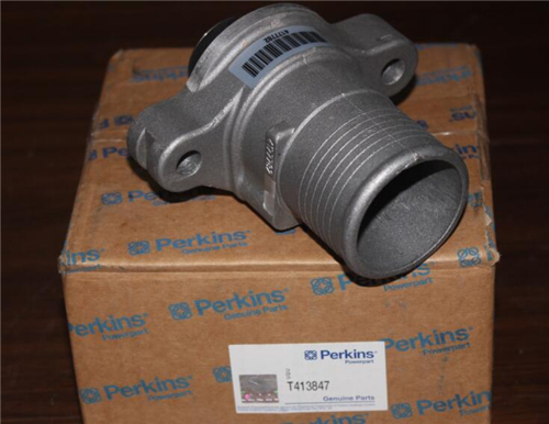
Perkins珀金斯1600柴油发动机1842130 C3恒温节温器
详细描述
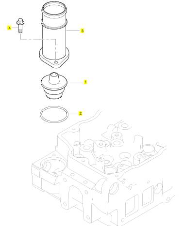
项目 零配件号码 新件号 描述
1 1842130 C3 1 1842130 C3 恒温节温器组合
2 1841771 C1 1 1841771 C1 密封O型圈
3 1844215 C2 1 1844215 C2 水出口连接
4 1817957 C1 2 1817957 C1 公制的螺拴
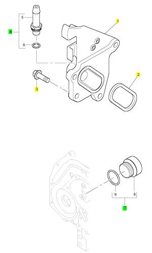
项目 零配件号码 新件号 描述
1 7079611 C1 1 7079611 C1 壳
2 1841479 C1 1 1841479 C1 密封
3 1818234 C1 4 1818234 C1 螺拴
4 1845852 C91 1 1845852 C91 承接器
7 1841845 C91 1 1841845 C91 栓塞
|
ymptom Troubleshooting |
|
i05352934 |
|
Alternator Is Noisy |
|
Note: This symptom is not an electronic system fault. |
|
Refer to Systems Operation, Testing and Adjusting for information on possible electrical causes of this condition. |
|
Probable Causes • Alternator drive belt and tensioner • Alternator mounting bracket • Alternator drive pulley |
|
• Alternator bearings |
|
Recommended Actions |
|
Note: The procedures have been listed in order of probability. Complete the procedures in order. |
|
This document has been printed from SPI2. NOT FOR RESALE. |
![]()
|
KENR8774 |
|
33 |
|
Symptom Troubleshooting |
|
Table 3 |
|
TroubleshootingTest Steps |
|
Values |
|
Results |
|
1. Alternator Drive Belt and Tensioner |
|
Drive belt |
|
Result: The alternator drive belt is in good condition and |
|
the belt tension is correct. |
|
A. Inspect the condition of the alternator drive belt. |
|
Proceed to Test Step 2. |
|
B. Check the belt tension. If necessary, check the automatic belt tensioner. |
|
Result: The alternator drive belts are not in good condition |
|
or the belt tension is incorrect. |
|
Note: Excessive belt tension can result in damage to the |
|
alternator. |
|
If the alternator drive belts are worn or damaged, replace the belts. Refer to Disassembly and Assembly for the cor- rect procedure. |
|
If necessary, replace the automatic belt tensioner. Refer to Disassembly and Assembly for the correct procedure. |
|
Result: The alternator drive belts are in good condition and the belt tension is correct. |
|
Proceed to Test Step 2. |
|
2. Alternator MountingBracket |
|
AlternatorMounting Result: The alternator mounting bracket is cracked and |
|
Bracket |
|
distorted. |
|
A. Inspect the alternator mounting bracket for cracks and distortion. |
|
Repair the mounting bracket or replace the mounting bracket. |
|
Note: The repair/replacement will ensure that the alternator drive belt and the alternator drive pulley are in alignment. |
|
Result: The alternator mounting bracket is OK. |
|
Proceed to Test Step 3. |
|
3. Alternator Drive Pulley |
|
Alternator Drive Pulley |
|
Result: There is excessive wear on the alternator drive pulley. |
|
A. Check the condition of the alternator drive pulley. Look for deep grooves that have been worn into the pulley by the belt. Check that the nut for the pulley has not become loose. |
|
Replace the pulley. |
|
Result: The alternator drive pulley nut was loose. Tighten the nut. |
|
Result: There is not excessive wear on the alternator drive pulley. |
|
Proceed to Test Step 4. |
|
4. Alternator Bearings |
|
Alternator bearings Result: The alternator bearings are not OK. |
|
A. Check the alternator bearings for signs of wear. |
|
Repair the alternator or replace the alternator, as needed. Refer to Disassembly and Assembly for the correct procedure. |
|
Result: The alternator bearings are OK. |
|
Contact Perkins Global Technical Support. |
|
This document has been printed from SPI2. NOT FOR RESALE. |

![]()
|
34 |
|
KENR8774 |
|
Symptom Troubleshooting |
|
i05354365 |
|
Alternator Problem |
|
Note: This symptom is not an electronic system fault. |
|
Probable Causes • Alternator drive belt and tensioner • Alternator |
|
• Charging circuit |
|
Recommended Actions |
|
Note: The procedures have been listed in order of probability. Complete the procedures in order. Table 4 |
|
TroubleshootingTest Steps |
|
Values |
|
Results |
|
Result: The alternator drive belts are not in good condition |
|
1. Alternator Drive Belt and Tensioner |
|
Drive belt |
|
or the belt tension is incorrect. |
|
A. Inspect the condition of the alternator drive belt. B. Check the belt tension. Check the automatic belt tensioner. |
|
If the alternator drive belts are worn or damaged, replace the belts. Refer to Disassembly and Assembly for the cor- rect procedure. |
|
Note: Excessive belt tension can result in damage to the alternator. |
|
If necessary, replace the automatic belt tensioner. Refer to Disassembly and Assembly for the correct procedure. |
|
Result: The alternator drive belts are in good condition and the belt tension is correct. |
|
Proceed to Test Step 2. |
|
2. Alternator |
|
Alternator |
|
Result: The alternator is not operating correctly. |
|
A. Verify that the alternator is operating correctly. |
|
Repair the alternatoror replace the alternator, as necessary. Refer to Disassembly and Assembly, “Alternator- Remove” and Disassembly and Assembly, “Alternator- Install” for the correct procedure. |
|
Result: The alternator is operating properly. |
|
Proceed to Test Step 3. |
|
3. Charging Circuit |
|
Charging circuit |
|
Result: The charging circuit is not operating correctly. |
|
A. Inspect the battery cables, wiring, and connections in the charging circuit. |
|
Clean all connections and tighten all connections. Replace any faulty parts. |
|
Result: The charging circuit is operating correctly. |
|
Contact Perkins Global Technical Support. |
|
This document has been printed from SPI2. NOT FOR RESALE. |

![]()
|
KENR8774 |
|
35 |
|
Symptom Troubleshooting |
|
i05354382 |
|
Battery Problem |
|
|
|
Probable Causes |
|
• Charging circuit • Battery |
|
• Auxiliary device |
|
Recommended Actions |
|
Complete the procedure in the order in which the steps are listed. |
|
Table 5 |
|
TroubleshootingTest Steps |
|
Values |
|
Results |
|
1. Charging Circuit |
|
Charging circuit |
|
Result: The charging circuit is not OK. Repair the charging circuit, as necessary. Result: The charging circuit is OK. Proceed to Test Step 2. |
|
A. Check that the battery charging circuit is operating correctly. Re- fer to Troubleshooting, “AlternatorProblem”. |
|
2. Battery |
|
Battery |
|
Result: The battery is not OK. |
|
A. Verify that the battery is no longer able to hold a charge. Refer to Systems Operation/Testing and Adjusting, “Battery - Test”. |
|
Replace the battery. Refer to the Operation and Maintenance Manual, “Battery - Replace”. |
|
Result: The battery is OK. |
|
Proceed to Test Step 3. |
|
3. Auxiliary Device |
|
Auxiliary Device |
|
Result: The battery has been drained by an auxiliary device being left in the ON position. |
|
A. Check if an auxiliary device has drained the battery by being left in the ON position. |
|
Charge the battery. Verify that the battery is able to maintain a charge. Refer to Systems Operation/Testing and Adjusting for the correct procedure. |
|
Result: The battery has not been drained by an auxiliary de- vice being left in the ON position. |
|
Contact Perkins Global Technical Support. |
|
This document has been printed from SPI2. NOT FOR RESALE. |

![]()
|
36 |
|
KENR8774 |
|
Symptom Troubleshooting |
|
i05355795 |
|
Coolant Contains Oil |
|
Recommended Actions Table 6 |
|
TroubleshootingTest Steps |
|
Values |
|
Results |
|
1. Engine Cooling System |
|
Oil Cooler |
|
Result: A leak is found in the engine cooling system. |
|
A. Inspect and test the engine cooling system for leaks. Refer to Systems Operation, Testing, and Adjusting, “Cooling Sys- tem” for the proper procedure. |
|
Repair any leaks. |
|
Flush the cooling system. Refer to the Operation and Main- tenance Manual for the correct procedure. Refill the cooling system with the correct coolant. Refer to the Operation and Maintenance Manual for the recommended coolant and capacities. |
|
Refill the engine with the proper oil after the leak has been repaired. Refer to the Operation and Maintenance Manual for the correct oil capacities and viscosity. |
|
Result: A leak was not found in the engine cooling system. |
|
Contact Perkins Global Technical Support. |
|
i05363437 |
|
Coolant Level Is Low |
|
Use this procedure when the engine coolant level is repeatedly found to be low or if the following diagnostic code is active: |
|
Table 7 |
|
Diagnostic Trouble Codes for Low Coolant Level Code Description |
|
DTC |
|
Comments |
|
323 |
|
Engine Coolant Level below warning/critical level |
|
The Electronic Control Module (ECM) detects that the engine coolant is low. When the Engine Warning Protection System (EWPS) mode is 3- way protection, the engine will shut down. |
|
After the shutdown, the engine can be restarted for 30 seconds. |
|
The ECM will log the engine hours at the time of the occurrence. When the coolant has returned to the correct level, the code will be- come inactive. |
|
Inspect the cooling system. Refer to Systems Operation, Testing, and Adjusting, “Cooling System - Test” for the correct procedure. |
|
This document has been printed from SPI2. NOT FOR RESALE. |
![]()
|
KENR8774 |
|
37 |
|
Symptom Troubleshooting |
|
i05355807 |
|
Coolant Temperature Is High |
|
Table 8 |
|
Diagnostic Trouble Codes for High Coolant Temperature |
|
DTC |
|
DTC Description |
|
Comments |
|
The Electronic Control Module (ECM) detects that the engine cool- ant temperatureis above 110° C (230° F). |
|
321 |
|
Engine Coolant Temperatureabove warning level |
|
The red engine lamp will come on. |
|
The DTC will become inactive when the coolant temperature is less than 110° C (230° F). |
|
The Electronic Control Module (ECM) detects that the engine cool- ant temperatureis above 112° C (234° F). |
|
322 325 |
|
Engine Coolant Temperatureabove critical level |
|
The red engine lamp will come on. The DTC will become inactive when the coolant temperature is less than 112° C (234° F). |
|
The Electronic Control Module (ECM) detects that the engine cool- ant temperatureis above 107° C (225° F). |
|
Power reduced, matched to cooling system performance |
|
The engine will be derated. |
|
The DTC will become inactive when the coolant temperature is less than 107° C (225° F). |
|
Probable Causes • Diagnostic codes |
|
• Coolant level |
|
• Coolant temperature sensor • Radiator and hoses • Radiator cap and pressure relief valve • Water temperature regulator • Engine cooling fan • Injector sleeves |
|
• Quality of coolant |
|
• Coolant pump |
|
• Cylinder head gasket • Cylinder head |
|
Recommended Actions |
|
Note: The procedures have been listed in order of probability. Complete the procedures in order. |
|
This document has been printed from SPI2. NOT FOR RESALE. |
![]()
|
38 |
|
KENR8774 |
|
Symptom Troubleshooting |
|
Table 9 |
|
TroubleshootingTest Steps |
|
Values |
|
Results |
|
1. DiagnosticCodes |
|
Diagnostic Codes |
|
Result: Diagnostic codes are not present. Return the unit to service. |
|
A. Use the electronic service tool to check for diagnostic codes that relate to the temperaturein the cooling system. |
|
Result: Diagnostic codes are present. Proceed to Test Step 2. |
|
2. Coolant Level |
|
Engine coolant level |
|
Result: The engine coolant level is low. |
|
A. Check the coolant level. |
|
Check the cooling system for leaks. Refer to Troubleshoot- ing, “Coolant Level is Low” for additional information. Re- pair any leaks immediately. |
|
Result: The engine coolant level is OK. |
|
Proceed to Test Step 3. |
|
3. Coolant Temperature Sensor |
|
Coolant tem- |
|
Result: The temperaturesensor is not accurate. |
|
perature sensor |
|
A. Compare the reading for the coolant temperatureon the elec- tronic service tool to the reading for the coolant temperature on a calibrated test gauge. |
|
Troubleshoot the circuit and the coolant temperature sen- sor. Refer to Troubleshooting, “Sensor Signal (Analog, Pas- sive) - Test”. |
|
Result: The temperaturesensor is reading accurately. |
|
Proceed to Test Step 4. |
|
4. Radiator and Hoses |
|
Radiator and hoses |
|
Result: The radiator fins are blocked or damaged. Remove any dirt and/or debris and straighten any bent fins. Result: The radiator has internal blockage. Remove the blockage. |
|
A. Check the radiator fins for dirt, debris, and/or damage. B. Check for collapsed hoses and/or other restrictions. C. Check the radiator for internal blockage. |
|
Result: The radiator fins are not damaged and the radiator does not have an internal blockage. |
|
Proceed to Test Step 5. |
|
5. Radiator Cap and Pressure Relief Valve |
|
Radiator cap |
|
Result: The pressure relief valve and/or the water tempera- |
|
ture regulator are not operating properly. |
|
A. Pressure-test the cooling system. Refer to Systems Operation, Testing, and Adjusting, “Cooling System” for the correct procedure. |
|
Clean the components or replace the components. |
|
Result: The pressure relief valve and/or the water tempera- |
|
B. Check that the seating surfaces of the pressure relief valve and the radiator cap are clean and undamaged. |
|
ture regulator are operating properly. |
|
Proceed to Test Step 6. |
|
C. Check operation of the pressure relief valve and/or the water temperature regulator. |
|
6. Water Temperature Regulator |
|
Water Temper- ature Regulator |
|
(continued) This document has been printed from SPI2. NOT FOR RESALE. |

![]()
|
KENR8774 |
|
39 |
|
Symptom Troubleshooting |
|
(Table 9, contd) |
|
TroubleshootingTest Steps |
|
Values |
|
Results |
|
Check the water temperatureregulator for correct operation. Refer to Systems Operation, Testing, and Adjusting, “Cooling System” for the proper procedure. |
|
Result: The water temperatureregulator is not operating correctly. |
|
Replace the water temperature regulator. Refer to Disas- sembly and Assembly, “Water TemperatureRegulator - Re- move and Install”. |
|
Result: The water temperatureregulator is operating correctly. |
|
Proceed to Test Step 7. |
|
7. Engine Cooling Fan |
|
Fan and drive Result: The drive belt is not tensioned correctly. |
|
belt |
|
A. Check for a loose drive belt. |
|
Check the automatic tensioner and replace the tensioner, if necessary. |
|
Note: A loose fan drive belt will cause a reduction in the air flow |
|
across the radiator. |
|
Result: The fan is damaged. |
|
B. Check the engine cooling fan for damage. |
|
Repair the fan or replace the fan, as necessary. Refer to Disassembly and Assembly, “Fan - Remove and Install”. |
|
Result: The fan is OK and the fan belt is tensioned correctly. |
|
Proceed to Test Step 8. |
|
8. Injector Sleeves |
|
Result: There were no bubbles present in the coolant. The |
|
coolant is not discolored. |
|
A. Switch off the engine and allow the engine to cool to below nor- mal working temperature. Remove the pressure cap for the cool- ant system. Start the engine and inspect the coolant for the presence of bubbles or discoloration of the coolant. |
|
Combustion gases are not leaking into the coolant. Contact Perkins Global Technical Support. |
|
Note: If bubbles are present in the coolant or the coolant is discol- ored, combustion gases may be entering the cooling system. |
|
Result: Coolant is leaking around the injector sleeves. |
|
Replace any leaking injector sleeves. Refer to Disassembly and Assembly, “Electronic Unit Injector Sleeve - Remove” and Disassembly and Assembly, “Electronic Unit Injector Sleeve - Install”. |
|
B. Remove the fuel injectors. Refer to Disassembly and Assembly, “Electronic Unit Injector - Remove”. |
|
C. Install a radiator pressure tester with the appropriate adaptor. D. Pressurize the cooling system to 96 kPa (14 psi). E. Look for coolant leaking around the injector sleeves. |
|
Result: There is no coolant leaking around the injector sleeves. |
|
Proceed to Test Step 9. |
|
9. Quality of Coolant |
|
Coolant |
|
Result: The coolant is not of an acceptable quality. |
|
A. Check the quality of the coolant. Refer to the Operation and Maintenance Manual, “Refill Capacities and Recommendations - Coolant”. |
|
Drain and refill the coolant system with coolant of the cor- rect quality. Refer to the Operation and Maintenance Man- ual, “Refill Capacities and Recommendations - Coolant”. |
|
Result: The coolant is of an acceptable quality. |
|
Proceed to Test Step 10. |
|
10. Inspection of the Coolant Pump |
|
Coolant pump |
|
(continued) This document has been printed from SPI2. NOT FOR RESALE. |

![]()
|
40 |
|
KENR8774 |
|
Symptom Troubleshooting |
|
(Table 9, contd) |
|
TroubleshootingTest Steps |
|
Values |
|
Results |
|
A. Inspect the impeller of the coolant pump for damage and/or erosion. |
|
Result The coolant pump is damaged or not operating correctly. |
|
B. Make sure that the drive gear is not loose on the drive shaft of the coolant pump. |
|
If necessary, replace the coolant pump. Refer to Disassem- bly and Assembly, “Water Pump - Remove” and Disassem- bly and Assembly, “Water Pump - Install”. |
|
Result The coolant pump is not damaged and the pump is operating correctly. |
|
Proceed to Test Step 11. |
|
11. Cylinder Head Gasket |
|
Cylinder Head Result: The cylinder head gasket is faulty or shows signs |
|
gasket |
|
of leakage. |
|
A. Remove the cylinder head. Refer to Disassembly and Assem- bly, “Cylinder Head - Remove” for the correct procedure. Inspect the cylinder head gasket for faults and any signs of leakage. |
|
Install a new cylinder head gasket. Result: The cylinder head gasket is OK. Proceed to Test Step 12. |
|
12. Cylinder Head |
|
Cylinder head Result: The cylinder head is not within specification for |
|
flatness. |
|
A. Check the cylinder head for flatness. Refer to Systems Opera- tion, Testing, and Adjusting, “Cylinder Head - Inspect” for the cor- rect procedure. |
|
Install a new cylinder head. Refer to Disassembly and As- sembly, “Cylinder Head - Install” for the correct procedure. |
|
B. Check the mating face of the cylinder head for faults and signs of leakage. If a fault is found, replace the cylinder head. If signs of leakage are found, determine the cause of the leakage. Refer to Systems Operation, Testing, and Adjusting, “Cylinder Head - In- spect” for the correct procedure. |
|
Result: The cylinder head shows signs of a fault or leakage. |
|
Install a new cylinder head. Refer to Disassembly and As- sembly, “Cylinder Head - Install” for the correct procedure. |
|
Result: The cylinder head is OK. |
|
Contact Perkins Global Technical Support. |
|
i05381112 |
|
Cylinder Is Noisy |
|
Recommended Actions |
|
Note: The procedures have been listed in order of probability. Complete the procedures in order. |
|
This document has been printed from SPI2. NOT FOR RESALE. |

![]()
|
KENR8774 |
|
41 |
|
Symptom Troubleshooting |
|
Table 10 |
|
TroubleshootingTest Steps |
|
Values |
|
Results |
|
1. DiagnosticCodes |
|
Codes |
|
Result: A diagnostic trouble code is active or logged. Troubleshoot the active or logged codes. Result: A diagnostic trouble code is not active or logged. Proceed to Test Step 2. |
|
A. Establish communication between the electronic service tool and the Electronic Control Module (ECM). |
|
B. Check for active diagnostic codes. |
|
2. Fuel Quality |
|
Fuel |
|
Result: The fuel quality is not OK. |
|
A. Check the fuel quality. Refer to Systems Operation, Testing, and Adjusting, “Fuel Quality - Test”. |
|
Drain the fuel system and replace the fuel filters. Refer to the Operation and Maintenance Manual, “Fuel System Pri- mary Filter - Clean/Inspect/ Replace” and Operation and Maintenance Manual, “Fuel System Secondary Filter - Replace”. |
|
B. Refer to Operation and Maintenance Manual for informationon the proper characteristics of the fuel for the engine. |
|
Fill the fuel system with fuel that meets the standard in the Operation and Maintenance Manual, “Fluid Recommendations”. |
|
Prime the fuel system. Refer to the Operation and Mainte- nance Manual, “Fuel System - Prime”. |
|
Verify that the procedure has eliminated the noise. Result: The fuel quality is OK. |
|
Proceed to Test Step 3. |
|
3. Valve Train Components |
|
Valve train |
|
Result: Valve train components are damaged. |
|
A. Check the valve lash. Refer to Systems Operation, Testing and Adjusting, “Engine Valve Lash - Inspect/Adjust”. |
|
Make the necessary repairs, Verify that the repair has elimi- nated the noise. |
|
B. Check for damage to valve train components. Remove the valve cover from the suspect cylinders. Check the following items for damage: |
|
Result: The valve train components are not damaged. |
|
Proceed to Test Step 4. |
|
· Valve springs |
|
· Rocker shaft |
|
· Bridges |
|
· Pushrods |
|
· Camshaft followers |
|
Refer to the Disassembly and Assembly for additional information. |
|
(continued) |
|
This document has been printed from SPI2. NOT FOR RESALE. |

![]()