 English
 Espaol
 Franais
 阿拉伯
阿拉伯 中文
中文 Deutsch
 Italiano
 Português
 日本
日本 韩国
韩国 български
 hrvatski
 esky
esky Dansk
Dansk Nederlands
 suomi
suomi Ελληνικ
 印度
印度 norsk
norsk Polski
 Roman
Roman русский
 Svenska
Perkins珀金斯1600柴油发动机2873 K116启动马达供应商,Perkins珀金斯1600柴油发动机2873 K116启动马达技术价格规格咨询服务,Perkins珀金斯1600柴油发动机2873 K116启动马达零配件供应,Perkins珀金斯1600柴油发动机2873 K116启动马达售后服务中心,Perkins珀金斯1600柴油发动机2873 K116启动马达,Perkins珀金斯1600柴油发动机2873 K116启动马达详细的技术参数,

产品中心
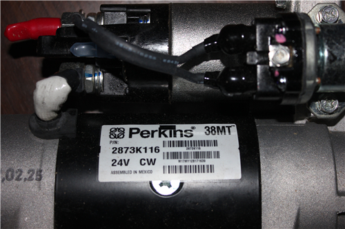
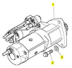
Perkins珀金斯1600柴油发动机2873 K116启动马达
详细描述
项目 零配件号码 新件号 描述
1 2873 K116 1 2873 K116 启动马达
2 2314 J706 3 2314 J706 螺旋
3 0920444 3 0920444 垫圈
|
Symptom Troubleshooting |
|
(Table 10, contd) |
|
TroubleshootingTest Steps |
|
Values |
|
Results |
|
4. Run the KOEO Injector Test |
|
Diagnostic codes |
|
Result: There are active diagnostic codes. |
|
A. Connect the electronic service tool to the diagnostic connector. B. Turn the keyswitch to the ON position. |
|
Troubleshoot all active diagnostic codes. Refer to Trouble- shootingDiagnostic Trouble Codes. Clear all active diagnostic codes and check that the repairs eliminate the fault. |
|
C. Select “Tests” from the menu bar. Select “Key-On Engine-Off” |
|
If the fault still exists, proceed to Test Step 5. |
|
from the drop-down menu. |
|
Result: There are no active diagnostic codes. |
|
Note: When running KOEO diagnostic tests, “Standard Test” is al- ways run first. If the ignition keyswitch is not cycled, the “Standard Test” does not need to be run again. |
|
Proceed to Test Step 5. |
|
D. From the KOEO Diagnostics menu, select “Injector”, then select “Run” . Note: During this test, injector solenoids should click in a numerical sequence. If a series of clicks are not heard for each injector, one or more injectors are not activating. |
|
E. Record all active diagnostic codes. |
|
5. Injector Disable Test |
|
Cylinders |
|
Result: The test indicates a suspect cylinder. |
|
Note:The injector disable test allows the technician to shut off injec- tors to determine if a specific cylinder is contributing to engine performance. |
|
Investigate the cause of the fault on any cylinder that is not operating. Investigate the cause of the fault on any cylinder that is operating below normal performance. |
|
A. Connect the electronic service tool to the diagnostic connector. B. Turn the keyswitch to the ON position. |
|
Note: Possible causes of low compression are shown in the following list: |
|
· Faulty piston |
|
C. Select “Tests” from the menu bar. Select “Injector Disable Test” from the drop-down menu. |
|
· Faulty piston rings · Worn cylinder bores · Worn valves |
|
Note: Monitor the engine oil temperature. Do not run the test until engine oil temperaturereaches 70° C (158° F) D. Select “Auto Run” . |
|
· Faulty cylinder head gasket · Damaged cylinder head |
|
Note: While running the engine, listen for sound variations from cyl- inder to cylinder. |
|
Result: The test indicates that all cylinders are OK. |
|
Proceed to Test Step 6. |
|
E. Record the results. |
|
6. Pistons |
|
Pistons |
|
Result: One or more pistons are worn or damaged. Replace any worn or damaged parts. |
|
A. Inspect the pistons for damage and wear. |
|
Verify that the repair has eliminated the noise. Result: All pistons are OK. |
|
Contact Perkins Global Technical Support. |
|
This document has been printed from SPI2. NOT FOR RESALE. |

![]()
|
KENR8774 |
|
43 |
|
Symptom Troubleshooting |
|
i05514011 |
|
ECM Does Not Communicate with Other Modules |
|
Table 11 |
|
Diagnostic Trouble Codes |
|
DTC |
|
DTC Description ECM/IDM communications fault |
|
Comments |
|
543 551 |
|
DTC 543 is set by the ECM when the ECM is not communicat- ing with the IDM |
|
IDM/CMPO signal inactive |
|
The Electronic Control module (ECM) detects the following conditions: |
|
There is no active Camshaft Position (CMPO) signal between the ECM and the Injector Driver Module (IDM). The Crankshaft Position (CKPO) signal is active or the ECM is reporting that the engine is in “RUN” mode. |
|
552 553 |
|
IDM incorrect CMPO signal signature IDM CKPO signal inactive |
|
The ECM detects the following condition: |
|
The CMPO transition occurs at the incorrect CKPO tooth. This diagnostic code can be caused by electrical noise creating a miscount on CMPO location. |
|
The ECM detects the following conditions: |
|
There is no active CKPO signal between the ECM and the IDM. The CMPO signal is active or the ECM is reporting that the en- gine is in “RUN” mode. |
|
554 |
|
IDM incorrect CKPO signal signature |
|
The ECM detects the following condition: The CKPO signal has too many or too few transitions per engine rotation. |
|
This diagnostic code can be caused by electrical noise creating a miscount on CKPO location. |
|
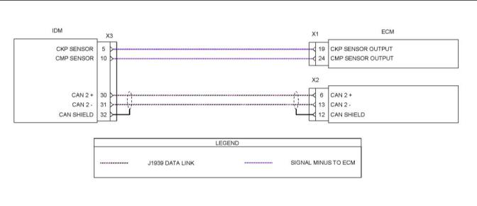
Illustration 20 |
|
g03408099 |
|
Schematic diagram of the ECM/IDM communications link |
|
This document has been printed from SPI2. NOT FOR RESALE. |

![]()
![]()
|
44 |
|
KENR8774 |
|
Symptom Troubleshooting |
|
The ECM/IDM communication link consists of a series of interdependent signals that include the CKPO, CMPO, and the CAN 2 datalink. |
|
The CKPO signal is a 0V to 12V signal that communicates (from ECM to IDM) the position of the crankshaft. The signal is used by the IDM to synchronize the injector firing sequence and is calculated from the signal generated from the CKP sensor. The ECM generates the CKPO signal by pulling down (switching to ground) a 12V |
|
communication circuit in the IDM. |
|
The CMPO signal is a 0V to 12V signal that communicates (from ECM to IDM) the position of the camshaft. The signal is used by the IDM to synchronize the injector firing sequence and is calculated from the signal generated from the CMP sensor. The ECM generates the CMPO signal by pulling down (switching to ground) a 12V |
|
communication circuit in the IDM. |
|
CAN 2 datalink is a J1939 high speed private |
|
communication datalink between the ECM, IDM, and EGR drive module. The ECM receives messages that include injector coil status, IDM calibration level, CMPO and CKPO DTCs, injector DTCs, IDM DTCs, and injector test results from the IDM. The IDM receives injector diagnostic commands, operation strategies, modes, and conditions from the ECM. |
|
Note: CAN 2 datalink is used only as communication between the ECM, IDM, and EGR drive module. There is no relation to the CAN 1 datalink that is used for communication with various processors on the application. |
|
Fault Detection/Management |
|
The ECM continuously monitors the IDM. When the ECM fails to receive required continuous communication from the IDM, the ECM will set an active diagnostic code. |
|
This document has been printed from SPI2. NOT FOR RESALE. |
![]()
|
KENR8774 |
|
45 |
|
Symptom Troubleshooting |
|
Table 12 |
|
Troubleshooting Test Steps |
|
Values |
|
Results |
|
1. DiagnosticCodes |
|
Diagnostic Codes Result: There are no active diagnostic codes. Return the unit to service. |
|
A. Use the electronic service tool to check for diagnostic codes that are listed in Table 11 . |
|
Result: There are active diagnostic codes. Proceed to Test Step 2. |
|
2. Check the CAN Data Link Signal to the ECM |
|
1V to 4V |
|
Result: The measured voltage is within the expected |
|
range. |
|
A. Turn the keyswitch to the OFF position. |
|
Proceed to Test Step 3. |
|
B. Disconnect the X1 and X2 ECM connectors. Thoroughly in- spect the terminal connections on the X1 and X2 ECM connec- tors. Refer to Troubleshooting, “Electrical Connectors - Inspect”. |
|
Result: The measured voltage is not within the expected range. |
|
C. Turn the keyswitch to the ON position. |
|
Proceed to Test Step 9. |
|
D. Use a suitable multimeter to measure the voltage between X2:6 on the harness connector and a suitable ground. |
|
E. Use a suitable multimeter to measure the voltage between X2:13 on the harness connector and a suitable ground. |
|
F. Turn the keyswitch to the OFF position. |
|
3. Check the Resistance of the CAN Data Link to Ground |
|
Greater than 1k Ohm |
|
Result: The measured resistance is less than 1k Ohm. Proceed to Test Step 4. |
|
A. Turn the keyswitch to the OFF position. |
|
B. Disconnect the negative battery cable. Use the disconnected negative battery cable for the ground test point. |
|
Result: The measured resistance is greater than 1k Ohm. Proceed to Test Step 5. |
|
C. Use a suitable multimeterto measure the resistance between ECM connector X2:6 and ground. |
|
Use a suitable multimeter to measure the resistance between ECM connector X2:13 and ground. |
|
4. Disconnect the IDM Connector and Recheck the CAN Da- Greater than 1k |
|
Result: The measured resistance is greater than 1k Ohm. |
|
ta Link Resistance |
|
Ohm |
|
Install a replacement IDM. |
|
A. Turn the keyswitch to the OFF position. B. Disconnect the IDM X3 connector. C. Repeat the resistance checks from Test Step 3. |
|
Use the electronic service tool to clear all logged diagnostic codes and verify that the repair eliminates the fault. |
|
Result: The measured resistance is less than 1k Ohm. |
|
The fault is in the wiring harness. |
|
Repair the harness or replace the harness. Use the electronic service tool to clear all logged diagnostic codes and verify that the repair eliminates the fault. |
|
5. Check the CAN Data Link for an Open Circuit |
|
Less than 5 Ohms Result: At least one of the resistance measurements is greater than 5 Ohms. |
|
A. Turn the keyswitch to the OFF position. |
|
The fault is in the wiring harness. |
|
(continued) This document has been printed from SPI2. NOT FOR RESALE. |

![]()
|
46 |
|
KENR8774 |
|
Symptom Troubleshooting |
|
(Table 12, contd) |
|
B. Use a suitable multimeter to measure the resistance between ECM X2:6 and IDM X3:30 on the harness connectors. |
|
Repair the faulty harness or replace the faulty harness. |
|
Result: All resistance measurements are less than 5 |
|
C. Use a suitable multimeterto measure the resistance between ECM X2:13 and IDM X3:31 on the harness connectors. |
|
Ohms. |
|
Proceed to Test Step 6. |
|
6. Check the CAN Data Link Resistance at the ECM Connector |
|
60 Ohms |
|
Result: The measured resistance is 60 Ohms. This is the correct resistance. |
|
If the fault persists, contact Perkins Global Technical Support. |
|
A. Turn the keyswitch to the OFF position. |
|
B. Use a suitable multimeter to measure the resistance between ECM X2:6 and X2:13 on the harness connector. |
|
Result: The measured resistance is greater than 60 Ohms. |
|
Proceed to Test Step 7. |
|
7. Check the ECM |
|
3.7 to 4.1 M Ohms Result: At least one of the resistance measurements is |
|
for Step B and Step C. |
|
incorrect. |
|
A. Remove the ECM. Refer to Disassembly and Assembly, “Electronic Control Module - Remove and Install”. |
|
Install a replacement ECM. Refer to Disassembly and As- sembly, “Electronic Control Module - Remove and Install”. |
|
120 Ohms for |
|
Note: Use ECM pin X3:6 or X3:7 as a ground test point for the Step D |
|
following steps. |
|
Result: All of the resistance measurements are OK. |
|
B. Use a suitable multimeter to measure the resistance between ECM X2:6 and ground. |
|
Proceed to Test Step 8. |
|
C. Use a suitable multimeterto measure the resistance between ECM X2:13 and ground. |
|
D. Use a suitable multimeterto measure the resistance between ECM X2:6 and X2:13. |
|
8. Check the IDM |
|
1.83 to 1.87 M |
|
Result: At least one of the resistance measurements is |
|
Ohms for Step B. |
|
incorrect. |
|
Remove the ECM. Refer to Disassembly and Assembly, “Elec- tronic Control Module - Remove and Install”. |
|
120 Ohms for Step C. |
|
Install a replacement IDM. Refer to Disassembly and As- sembly, “Electronic Control Module - Remove and Install”. |
|
Note: Use one of the following pins on the IDM as a ground test point for the following steps: |
|
5 Ohms for Step Result: All of the resistance measurements are OK. |
|
X3:1, X3:2, X3:3, X3:22, or X3:26. |
|
D. |
|
If the fault persists, contact Perkins Global Technical Support. |
|
B. Use a suitable multimeter to measure the resistance between IDM X3:30 and ground. |
|
Use a suitable multimeter to measure the resistance between X3:31 and ground. |
|
C. Use a suitable multimeterto measure the resistance between IDM X3:30 and X3:31. |
|
D. Use a suitable multimeterto measure the resistance between X3:32 and ground. Use a suitable multimeter to measure the resistance between the IDM housing and ground. |
|
9. Check the CKPO and CMPO Voltage |
|
11 V to 12 V |
|
Result: The voltage is within the expected range. |
|
A. Turn the keyswitch to the OFF position. |
|
(continued) This document has been printed from SPI2. NOT FOR RESALE. |

![]()
|
KENR8774 |
|
47 |
|
Symptom Troubleshooting |
|
(Table 12, contd) |
|
Disconnect the ECM X1 connector. |
|
If the fault persists, contact Perkins Global Technical Support. |
|
C. Turn the keyswitch to the ON position. |
|
Result: The voltage is not within the expected range. |
|
D. Use a suitable multimeter to measure the voltage between ECM X1:19 on the harness connector and a suitable ground. Use a suitable multimeter to measure the voltage between ECM X1:24 on the harness connector and a suitable ground. |
|
Proceed to Test Step 10. |
|
E. Turn the keyswitch to the OFF position. |
|
10. Check the CKPO and CMPO Resistance to Ground |
|
Greater than 1k Ohm |
|
Result: The measured resistance is less than 1k Ohm. Proceed to Test Step 11. |
|
A. Turn the keyswitch to the OFF position. |
|
B. Disconnect the negative battery cable. Use the disconnected negative battery cable for the ground test point. |
|
Result: The measured resistance is greater than 1k Ohm. |
|
If the fault persists, contact Perkins Global Technical Support. |
|
C. Use a suitable multimeterto measure the resistance between ECM connector X1:24 and ground. |
|
11. Disconnect the IDM Connector and Recheck the CKPO Greater than 1k |
|
Result: The measured resistance is greater than 1k Ohm. |
|
and CMPO Resistance to Ground |
|
Ohm |
|
Install a replacement IDM. |
|
A. Turn the keyswitch to the OFF position. B. Disconnect the IDM X3 connector. |
|
Use the electronic service tool to clear all logged diagnostic codes and verify that the repair eliminates the fault. |
|
Result: The measured resistance is less than 1k Ohm. |
|
C. Repeat the resistance checks from Test Step 10. |
|
The fault is in the wiring harness. |
|
Repair the harness or replace the harness. Use the electronic service tool to clear all logged diagnostic codes and verify that the repair eliminates the fault. |
|
i05434202 |
|
Electronic Service Tool Does Not Communicate |
|
Probable Causes |
|
• Configuration of the communications adapter • Electrical connectors |
|
• Communication adapter and/or cables |
|
• Electrical power supply to the diagnostic connector • Electronic service tool and related hardware |
|
• Electrical power supply to the Electronic Control Module (ECM) |
|
• Data Link |
|
Recommended Actions |
|
Note: The procedures have been listed in order of probability. Complete the procedures in order. This document has been printed from SPI2. NOT FOR RESALE. |

![]()
|
48 |
|
KENR8774 |
|
Symptom Troubleshooting |
|
Table 13 |
|
TroubleshootingTest Steps |
|
Values |
|
Results |
|
1. Configuration of the Communications Adapter |
|
Communications adapter |
|
Result: The correct “Communications Interface Device” is not selected. |
|
A. Access “Select Com Link” under the “Tools” menu on the |
|
configuration |
|
electronic service tool. |
|
Select the correct “Communications Interface Device” . |
|
B. Check for hardware that uses the same ports as the commu- nications adaptor. |
|
Result: The correct port is not selected for use by the com- munication adapter. |
|
Select the correct port for use by the communication adapter. |
|
Result: Other hardware is sharing the same port with the communications adaptor. |
|
Exit or close the software programs for that device. |
|
Result: The communications adaptor is correctly configured. |
|
Proceed to Test Step 2. |
|
2. Electrical Connectors |
|
Electrical connectors |
|
Result: The connectors are not correctly installed. Repair or replace the connectors, as necessary. Result: The connectors are OK. |
|
A. Check for correct installation of the following connectors: |
|
· ECM connectors · IDM connectors · Power connector ·Diagnostic connector |
|
Proceed to Test Step 3. |
|
3. Communication Adapter and/or Cables |
|
Comms adaptor Result: The firmware or driver files are not the most cur- |
|
and cables |
|
rent files. |
|
A. Check that the firmware and driver files are the most current files for the type of communication adapter that is being used. |
|
Update the firmware or driver files to the most current files. |
|
Verify that the correct cable is being used between the commu- nication adapter and the diagnostic connector. |
|
Result: The cable between the communication adapter and the diagnostic connector is not correct. |
|
B. Disconnect and then reconnect the cable that attaches the communication adapter to the diagnostic connector. |
|
Replace the cable between the communication adapter and the diagnostic connector with the correct type. |
|
C. Check the operating system on the laptop computer. |
|
Result: The laptop computer has a Windows operating |
|
system. |
|
Restart the laptop computer in order to eliminate the possi- bility of a conflict in the software. |
|
Result: The adaptor and cables are OK. |
|
Proceed to Test Step 4. |
|
(continued) |
|
This document has been printed from SPI2. NOT FOR RESALE. |

![]()
|
KENR8774 |
|
49 |
|
Symptom Troubleshooting |
|
(Table 13, contd) |
|
TroubleshootingTest Steps |
|
Values |
|
Results |
|
4. Electrical Power Supply to the Diagnostic Connector |
|
Electrical power Result: Battery voltage is not present between terminals A |
|
and B of the diagnostic connector. |
|
A. Use a multimeter to check that battery voltage is present be- tween terminals A and B of the diagnostic connector. |
|
Investigate the cause and repair, as necessary. |
|
Note: If the communication adapter is not receiving power, the |
|
Result: Battery voltage is present between terminals A |
|
LED display on the communication adapter will be off. |
|
and B of the diagnostic connector. |
|
Proceed to Test Step 5. |
|
5. Electronic Service Tool and Related Hardware |
|
Hardware Power to ECM Data link OK |
|
Result: The same fault occurs on a different engine. |
|
A. Connect the electronic service tool to a different engine. |
|
Check the electronic service tool and the related hardware for faults. |
|
Note: This process eliminates the electronic service tool and the related hardware as the fault. |
|
Result: The fault does not occur on a different engine. |
|
Proceed to Test Step 6. |
|
6. Electrical Power Supply to the Electronic Control Mod- ule (ECM) |
|
Result: The power supply to the ECM is incorrect. Investigate the cause and repair, as necessary. Result: The power supply to the ECM is OK. Proceed to Test Step 7. |
|
A. Check the power supply to the ECM. Refer to Systems Op- eration, Testing, and Adjusting, “Charging System - Test”. |
|
Note: If the ECM is not receiving battery voltage, the ECM will not communicate. |
|
7. Data Link |
|
Result: A fault was identified in the data link . |
|
Repair the fault. |
|
A. Troubleshoot the Data Link for possible faults. Refer to Trou- bleshooting, “Data Link - Test” and Troubleshooting, “CAN Data Link - Test”. |
|
Return the unit to service. |
|
Result: The data link is OK. |
|
Contact Perkins Global Technical Support. |
|
i05435142 |
|
Engine Cranks but Does Not Start |
|
Recommended Actions |
|
NOTICE |
|
Do not crank the engine continuously for more than 30 seconds. Allow the starting motor to cool for two minutes before cranking the engine again. |
|
Note: Complete the procedures in order. |
|
This document has been printed from SPI2. NOT FOR RESALE. |

![]()
![]()
![]()
|
50 |
|
KENR8774 |
|
Symptom Troubleshooting |
|
Table 14 |
|
TroubleshootingTest Steps |
|
Values |
|
Results |
|
1. Engine Inspection |
|
Faults |
|
Result: Faults found during inspection. |
|
A. Turn the keyswitch to the OFF position. |
|
Rectify any faults an attempt to start the engine. If the engine will not start, proceed to Test Step 9. |
|
B. Inspect the high-pressure oil line from the high-pressure pump to the supply manifold for major leaks. |
|
Result: No faults found. |
|
C. Check the engine oil system for leaks. |
|
Proceed to Test Step 2. |
|
D. Inspect the engine cooling system for leaks. |
|
E. Inspect the engine sensors, relay, ECM, and IDM connec- tions. All connections must be seated, in good condition, and free from damage or corrosion. |
|
F. Inspect the battery cables and fuse connections for corrosion. |
|
G. Inspect the engine wiring harness for correct routing and pro- tection against rubbing or chaffing. |
|
F. Inspect the air inlet and exhaust systems. Refer to Systems Operation, Testing and Adjusting, “Air Inlet and Exhaust System - Inspect”. |
|
2. Initial Ignition Switch ON (Do not Start) |
|
Wait to Start lamp |
|
Result: No injector pre-cycle. |
|
Check the power supply to the Electronic Control Module |
|
A. Turn the keyswitch to the ON position. Do not attempt to start the engine. |
|
Water in Fuel (ECM) and the Injector Driver Module (IDM). Refer to Trou- |
|
lamp |
|
bleshootingElectrical Power Supply - Test. |
|
B. Check or listen for the following: ·Wait to Start lamp comes on and goes off ·Water in Fuel lamp comes on and goes off ·Injector pre-cycle noise |
|
Injector pre-cycle Result: Water in Fuel lamp stays on. Refer to TroubleshootingFuel Contains Water. |
|
Result: Wait to Start lamp does not come on. Check the power supply to the ECM . Refer to Troubleshoo- tingElectrical Power Supply - Test. |
|
Result: All OK. |
|
Proceed to Test Step 3. |
|
(continued) |
|
This document has been printed from SPI2. NOT FOR RESALE. |

![]()
|
KENR8774 |
|
51 |
|
Symptom Troubleshooting |
|
(Table 14, contd) |
|
TroubleshootingTest Steps |
|
Values |
|
Results |
|
3. Engine Cranking |
|
130 rpm |
|
Result: The engine will not crank. |
|
A. Connect the electronic service tool to the diagnostic connector. |
|
130 kPa(19 psi) Refer to Troubleshooting, “Engine Does Not Crank”. crankcase oil |
|
pressure |
|
Result: The recorded engine speed is below 130 rpm |
|
B. Turn the keyswitch to the START position. |
|
Minimal exhaust Check that the battery has sufficient power. Refer to Sys- |
|
C. Record the engine rpm while the engine is cranking. D. Record the engine oil pressure while the engine is cranking. E. Check for exhaust smoke and record color. |
|
smoke |
|
tems Operation, Testing and Adjusting, “Battery - Test” Check the starting motor. Refer to Systems Operation, Test- ing and Adjusting, “Electrical Starting System - Test” Check that the correct engine oil is being used for the ambi- ent temperature. Refer to Operation and Maintenance Man- ual, “Fluid Recommendations” |
|
Result: The recorded crankcase oil pressure is below 130 kPa(19 psi). |
|
Refer to Troubleshooting, “Oil Pressure Is Low”. |
|
Result: Excessive black smoke or excessive white is ob- served during cranking. Refer to TroubleshootingExhaust Has Excessive Black Smoke or TroubleshootingExhaust Has Excessive White Smoke |
|
Result: No exhaust smoke observed during cranking. |
|
Check that the fuel supply valve (if equipped) is in the OPEN position. |
|
Result: All checks are OK. |
|
Proceed to Test Step 4. |
|
4. Check for Active Diagnostic Codes |
|
Diagnostic codes Result: There are active diagnostic codes. Troubleshoot all active diagnostic codes. Refer to Trouble- shootingDiagnostic Trouble Codes. Clear all active diagnostic codes and attempt to start the engine. |
|
A. Connect the electronic service tool to the diagnostic connector. |
|
B. Turn the keyswitch to the ON position. C. Record all active diagnostic codes. |
|
If the engine will not start, proceed to Test Step 4. |
|
Result: There are no active diagnostic codes. Proceed to Test Step 5. |
|
(continued) |
|
This document has been printed from SPI2. NOT FOR RESALE. |

![]()
|
52 |
|
KENR8774 |
|
Symptom Troubleshooting |
|
(Table 14, contd) |
|
TroubleshootingTest Steps |
|
Values |
|
Results |
|
5. Run the Key-On Engine-Off (KOEO) Standard Test |
|
Diagnostic codes Result: There are active diagnostic codes. |
|
A. Connect the electronic service tool to the diagnostic connector. |
|
Troubleshoot all active diagnostic codes. Refer to Trouble- shootingDiagnostic Trouble Codes. |
|
Clear all active diagnostic codes and attempt to start the engine. |
|
B. Turn the keyswitch to the ON position. |
|
If the engine will not start, proceed to Test Step 6. |
|
C. Select “Tests” from the menu bar. Select “Key-On Engine- Off” from the drop-down menu. |
|
Result: There are no active diagnostic codes. |
|
D. From the KOEO Diagnostics menu, select “Standard” , then select “Run” . |
|
Proceed to Test Step 6. |
|
Note: This test takes less than 5 seconds. |
|
E. Record all active diagnostic codes. |
|
6. Run the KOEO Injector Test |
|
Diagnostic codes Result: There are active diagnostic codes. |
|
A. Connect the electronic service tool to the diagnostic connector. |
|
Troubleshoot all active diagnostic codes. Refer to Trouble- shootingDiagnostic Trouble Codes. |
|
Clear all active diagnostic codes and attempt to start the engine. |
|
B. Turn the keyswitch to the ON position. |
|
If the engine will not start, proceed to Test Step 6. |
|
C. Select “Tests” from the menu bar. Select “Key-On Engine- Off” from the drop-down menu. |
|
Result: There are no active diagnostic codes. |
|
Note: When running KOEO diagnostic tests, “Standard Test” is always run first. If the ignition keyswitch is not cycled, the “Standard Test” does not need to be run again. D. From the KOEO Diagnostics menu, select “Injector” , then select “Run” . |
|
Proceed to Test Step 7. |
|
Note: During this test, injector solenoids should click in a numer- ical sequence. If a series of clicks are not heard for each injector, one or more injectors are not activating. |
|
E. Record all active diagnostic codes. |
|
(continued) |
|
This document has been printed from SPI2. NOT FOR RESALE. |

![]()
|
KENR8774 |
|
53 |
|
Symptom Troubleshooting |
|
(Table 14, contd) |
|
TroubleshootingTest Steps |
|
Values |
|
Results |
|
7. Monitor Data While the Engine Is Cranking |
|
8.3 VDC battery Result: The battery voltage is below 8.3 VDC. |
|
voltage |
|
A. Connect the electronic service tool to the diagnostic connector. |
|
Refer to Troubleshooting, “Electrical Power Supply - Test” 130 rpm engine |
|
speed |
|
Result: The recorded engine speed is below 130 rpm |
|
B. Crank the engine for 20 seconds and record the following val- ues using the electronic service tool: · Battery voltage |
|
5 MPa (725 psi) Check that the battery has sufficient power. Refer to Sys- |
|
ICP |
|
tems Operation, Testing and Adjusting, “Battery - Test” |
|
· Engine speed (rpm) |
|
Check the starting motor. Refer to Systems Operation, Test- |
|
·Injection Control Pressure (ICP) |
|
0% EGR valve ing and Adjusting, “Electrical Starting System - Test” |
|
·Exhaust Gas Recirculation (EGR) valve position |
|
position |
|
Check that the correct engine oil is being used for the ambi- ent temperature. Refer to Operation and Maintenance Man- ual, “Fluid Recommendations” |
|
Result: The recorded ICP is less than 5 MPa (725 psi). |
|
Refer to Troubleshooting, “Injection Actuation Pressure Problem”. |
|
The EGR valve position is not 0%. |
|
Replace the EGR valve. Refer to Disassembly and Assem- bly, “Exhaust Gas Recirculation Valve - Remove and Install”. |
|
Result: All parameters are within the specifications. |
|
Proceed to Test Step 8. |
|
8. Fuel System |
|
Fuel system faults |
|
Result: Fuel system faults found. |
|
A. Check the fuel level in the fuel tank. |
|
Rectify any faults and attempt to start the engine. If the engine will not start, proceed to Test Step 8. |
|
B. Ensure that the fuel filters have been serviced at the correct interval. Refer to Operation and Maintenance Manual, “Mainte- nance Interval Schedule” |
|
Result: No faults found Proceed to Test Step 9. |
|
C. Ensure that there is no air in the fuel system. Refer to Opera- tion and Maintenance Manual, “Fuel System - Prime” |
|
D. Ensure that the correct fuel is being used. Refer to Operation and Maintenance Manual, “Fluid Recommendations”. |
|
E. Inspect the fuel system for the following faults: · Fuel supply line broken or crimped · Fuel tank pickup tube clogged or cracked · Ice in the fuel lines |
|
· Debris in the fuel tank |
|
(continued) |
|
This document has been printed from SPI2. NOT FOR RESALE. |

![]()
|
54 |
|
KENR8774 |
|
Symptom Troubleshooting |
|
(Table 14, contd) |
|
TroubleshootingTest Steps |
|
Values |
|
Results |
|
9. Engine Oil |
|
Correct oil level Result: The oil level is too high. |
|
A. Turn the keyswitch to the OFF position. |
|
Refer to Troubleshooting, “Oil Contains Coolant”. or Trou- bleshooting, “Oil Contains Fuel”. |
|
B. Check the engine oil level. Refer to Operation and Mainte- nance ManualEngine Oil Level - Check. |
|
Result: The oil level is too low. Refer to Troubleshooting, “Oil Consumption Is Excessive” or Troubleshooting, “Oil Pressure Is Low”. |
|
Result: The oil level is OK. Proceed to Test Step 10. |
|
10. Inlet Air Heater System (if equipped) |
|
115 amps to 135 Result: At least one of the amperage readings is not within |
|
amps |
|
the specifications. |
|
A. Turn the keyswitch to the OFF position. |
|
Replace the air inlet heater. Check that the engine starts normally. |
|
B. Install a clamp-on ammeter around one of the feed wires to the air inlet heater. |
|
If the engine will not start, contact Perkins Global Technical Support. |
|
Note: When running KOEO diagnostic tests, “Standard Test” is always run first. If the ignition keyswitch is not cycled, the “Standard Test” does not need to be run again. |
|
Result: The amperage readings are within specifications. |
|
Contact Perkins Global Technical Support. |
|
C. Select “Tests” from the menu bar. Select “Key-On Engine- Off” from the drop-down menu. |
|
D. From the KOEO Diagnostics menu, select “Glow Plug/Inlet Air Heater” , then select “Run” . |
|
E. Record the amperage reading. |
|
F. Repeat the test for the other ai inlet heater feed wire. |
|
i05438756 |
|
Engine Does Not Crank |
|
Recommended Repairs |
|
Complete the procedure in the order in which the steps are listed. |
|
This document has been printed from SPI2. NOT FOR RESALE. |