 English
 Espaol
 Franais
 阿拉伯
阿拉伯 中文
中文 Deutsch
 Italiano
 Português
 日本
日本 韩国
韩国 български
 hrvatski
 esky
esky Dansk
Dansk Nederlands
 suomi
suomi Ελληνικ
 印度
印度 norsk
norsk Polski
 Roman
Roman русский
 Svenska
Perkins珀金斯850-854F柴油发动机3940930发动机控制模块ecm供应商,Perkins珀金斯850-854F柴油发动机3940930发动机控制模块ecm技术价格规格咨询服务,Perkins珀金斯850-854F柴油发动机3940930发动机控制模块ecm零配件供应,Perkins珀金斯850-854F柴油发动机3940930发动机控制模块ecm售后服务中心,Perkins珀金斯850-854F柴油发动机3940930发动机控制模块ecm,Perkins珀金斯850-854F柴油发动机3940930发动机控制模块ecm详细的技术参数,

产品中心
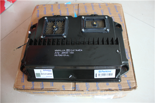
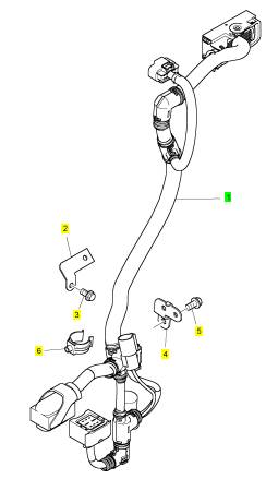
Perkins珀金斯850-854F柴油发动机3940930发动机控制模块ecm、控制线
详细描述
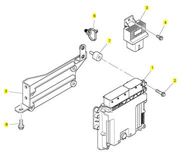
项目 零配件号码 最新件号 描述
1 3940930 1 3940930 发动机控制模块ecm
2 2314 F005 4 2314 F005 螺旋
3 T410586 1 T410586 接替者
4 2314 F003 1 2314 F003 螺旋
5 T415459 1 T415459 托架
6 T409240 2 T409240 缆拉杆
7 T414518 4 T414518 架设
8 2314 H003 3 2314 H003 螺旋
项目 零配件号码 最新件号 描述
1 T415463 1 T415463 线束
2 T415391 1 T415391 托架
3 2314 H002 1 2314 H002 螺旋
4 T415399 1 T415399 托架
5 2314 H002 1 2314 H002 螺旋
6 2481 D501 1 2481 D501 夹
|
Table of Contents |
|
Flexible Exhaust Pipe - Remove and Install |
|
(Flexible Exhaust Pipe for Top Mounted Clean Emission Module (CEM))............... ............... 50 Exhaust Manifold - Remove and Install (Exhaust Manifold for 403F-15T Engine)........... .......... 51 Exhaust Manifold - Remove and Install (Exhaust Manifold for 404F-22 and 404F-22T)...... ...... 53 Exhaust Elbow - Remove and Install (Exhaust Elbow between the (Aftertreatment Regeneration Device (ARD) and the Clean Emission Module (CEM))............... ............... 55 Exhaust Elbow - Remove and Install (Exhaust Elbow between the Turbocharger and the Aftertreatment Regeneration Device (ARD)) 56 Diesel Particulate Filter - Remove......... ......... 58 Diesel Particulate Filter - Remove......... ......... 59 Diesel Particulate Filter - Install........... ........... 61 Diesel Particulate Filter - Install........... ........... 63 Support and Mounting (CEM) - Remove and Install (Support and Mounting (CEM) for 404F- 22 Engines).......................... ......................... 65 Support and Mounting (CEM) - Remove and Install (Support and Mounting (CEM) for 403F- 15T Engines) ........................ ........................ 66 Support and Mounting (CEM) - Remove and Install (Support and Mounting for Rear mounted Clean Emission Module (CEM)) .......... ......... 68 Inlet Manifold - Remove and Install (Inlet |
|
Disassembly and Assembly Section |
|
Fuel Priming Pump - Remove and Install |
|
(Electrical Fuel Priming Pump for 404F-22 and 404F-22T Engines)..................... .................... 5 Fuel Priming Pump - Remove and Install |
|
(Electrical Fuel Priming Pump for 403F-15T Engines)............................. ............................. 7 Fuel Filter Base - Remove and Install (Fuel Filter Base for 403F-15T, 404F-22, and 404F-22T Engines)............................. ............................. 9 Fuel Injection Lines - Remove and Install (Fuel Injection Lines and Leak Off Rail for 403F-15T, 404T-22, and 404F-22T Engines)......... ........ 12 Exhaust Cooler (NRS) - Remove and Install. . 14 Position Sensor (Governor Control) - Remove and Install (Fuel Rack Solenoid).......... ......... 17 Fuel Injection Pump - Remove ............ ........... 18 Fuel Injection Pump - Install .............. ............. 20 Fuel Injector - Remove and Install (Fuel Injector for 403F-15T, 404F-22, and 404F-22T |
|
Engines)............................ ............................ 21 Fuel Injector - Remove and Install (AftertreatmentRegeneration Device (ARD) Primary Fuel Injector).................. .................. 22 Fuel Injector - Remove and Install |
|
Manifold for 404F-22T Engines) .......... ......... 69 Inlet and Exhaust Valve Springs - Remove and Install............................... .............................. 71 Inlet and Exhaust Valves - Remove and Install 73 Engine Oil Line - Remove and Install ....... ...... 76 Engine Oil Cooler - Remove and Install..... ..... 78 Engine Oil Relief Valve - Remove and Install. 80 Engine Oil Pump - Remove.............. .............. 81 Engine Oil Pump - Install................ ................ 83 Water Pump - Remove and Install (403F-15T, 404F-22 and 404F-22T Engines)......... ......... 86 Water Temperature Regulator Housing - Remove and Install........................... ........................... 88 Flywheel - Remove and Install............ ............ 91 Crankshaft Rear Seal - Remove and Install .. . 93 Crankshaft Wear Sleeve (Rear) - Remove and Install............................... .............................. 95 Flywheel Housing - Remove and Install |
|
(AftertreatmentRegeneration Device (ARD) Secondary Fuel Injector)................ ............... 24 Air Cleaner - Remove and Install.......... .......... 27 Turbocharger - Remove (Turbocharger for 404F- 22T Engines) ........................ ........................ 28 Turbocharger - Remove (Turbocharger for 403F- 15T Engines) ........................ ........................ 30 Turbocharger - Install (Turbocharger for 404F- 22TEngines) ......................... ........................ 31 Turbocharger - Install (Turbocharger for 403F- 15T Engines) ........................ ........................ 33 Check Valve (ARD Air Supply) - Remove and Install............................... .............................. 35 Exhaust Gas Recirculation Valve - Remove and Install............................... .............................. 37 Aftertreatment Regeneration Device (ARD) - Remove and Install.................... ................... 39 Pump (ARD Air) - Remove and Install (Pump (ARD Air) Low Mounted)................ ............... 42 Pump (ARD Air) - Remove and Install (High Mounted Pump (ARD Air)).............. .............. 45 Belt (ARD Air Pump) - Remove and Install... .. 48 |
|
(Engines with Flywheel Housing and Back |
|
Plate)............................... .............................. 96 Flywheel Housing - Remove and Install..... .... 99 Crankshaft Pulley - Remove and Install.... .... 100 Crankshaft Front Seal - Remove and Install. 102 |
|
This document is printed from SPI². Not for RESALE |
![]()
|
4 |
|
KENR9145 |
|
Table of Contents |
|
Housing (Front) - Remove.............. .............. 103 Housing (Front) - Disassemble........... .......... 105 Housing (Front) - Assemble............. ............. 107 Housing (Front) - Install................ ................ 109 Crankcase Breather - Remove and Install (For 403F-15T Engines)................... ...................111 Crankcase Breather - Remove and Install (For 404F-22T Engine).................... ....................114 Crankcase Breather - Remove and Install (Naturally Aspirated 404F-22 Engine) .... .....116 Valve Mechanism Cover - Remove and Install (Valve Mechanism Cover for 404F-22T Engines)............................ ...........................118 Valve Mechanism Cover - Remove and Install (Valve Mechanism Cover for 404F-22 Engines)........................... ........................... 120 Valve Mechanism Cover - Remove and Install (Valve Mechanism Cover for 403F-15T Engines)........................... ........................... 123 Rocker Shaft and Pushrod - Remove...... ..... 126 Rocker Shaft - Disassemble (Rocker Shaft for 403F-15T, 404F-22, and 404F-22T Engines)........................... ........................... 127 Rocker Shaft - Assemble (Rocker Shaft for 403F-15T, 404F-22, and 404F-22T Engines)........................... ........................... 128 Rocker Shaft and Pushrod - Install........ ....... 129 Cylinder Head - Remove (Cylinder Head for 403F-15T, 404F-22T, and 404F-22Engines) 130 Cylinder Head - Install (Cylinder Head for 403F- 15T, 404F-22, and 404F-22T Engines).... ... 132 Lifter Group - Remove and Install......... ........ 134 Camshaft - Remove (Camshaft for 403F-15T, 404F-22, and 404F-22T Engines)........ ....... 135 Camshaft - Disassemble ............... ............... 136 Camshaft - Assemble .................. ................. 137 Camshaft - Install (Camshaft for 403F-15T, 404F-22, and 404F-22T Engines)........ ....... 138 Engine Oil Pan - Remove and Install...... ...... 139 Balancer - Remove.................... ................... 141 Balancer - Install...................... ..................... 141 Pistons and Connecting Rods - Remove... ... 143 Pistons and Connecting Rods - Disassemble144 Pistons and Connecting Rods - Assemble.. . 146 Pistons and Connecting Rods - Install..... ..... 148 Connecting Rod Bearings - Remove (Connecting Rods in Position)..................... .................... 150 Connecting Rod Bearings - Install (Connecting Rods in Position)..................... .................... 150 |
|
Crankshaft Main Bearings - Remove (Crankshaft Main Bearings for 403F-15T, 404F-22, and 404F-22T Engines)................... .................. 151 Crankshaft Main Bearings - Install (Crankshaft Main Bearings for 403F-15T, 404F-22, and |
|
404F-22T Engines)................... .................. 154 Crankshaft - Remove.................. .................. 156 Crankshaft - Install.................... .................... 157 Crankshaft Gear - Remove and Install ..... .... 158 Crankshaft Gear (Balancer Drive) - Remove and Install.............................. ............................. 160 Bearing Clearance - Check ............. ............. 161 Secondary Engine Speed/Timing Sensor - Remove and Install................... .................. 162 Primary Engine Speed/Timing Sensor - Remove and Install.......................... .......................... 163 Coolant Temperature Sensor - Remove and Install.............................. ............................. 163 Engine Oil Pressure Switch - Remove and Install (Engine Oil Pressure Switch in the Cylinder Block)............................. ............................. 164 Engine Oil Pressure Switch - Remove and Install (Engine Oil Pressure Switch in Valve Mechanism Cover)................... ................... 166 Flame Detection Temperature Sensor - Remove and Install.......................... .......................... 167 Temperature Sensor (DPF) - Remove and Install (Temperature Sensor for the DPF Outlet).. . 168 Temperature Sensor (DPF) - Remove and Install (Temperature Sensor for the DPF Inlet)... ... 169 Temperature Sensor (Catalyst Inlet) - Remove and Install.......................... .......................... 170 Pressure Sensor (DPF) - Remove and Install 171 Boost Pressure Sensor - Remove and Install 173 Turbocharger Inlet Temperature Sensor - Remove and Install................... .................. 174 Inlet Manifold Temperature Sensor - Remove and Install.......................... .......................... 175 Glow Plug - Remove and Install (Glow Plug for the AftertreatmentRegeneration Device (ARD) for 403F-15T, 404F-22, and 404F-22T |
|
Engines)........................... ........................... 176 Glow Plugs - Remove and Install......... ......... 177 V-Belts - Remove and Install ............ ............ 178 Fan - Remove and Install............... ............... 179 Alternator - Remove and Install.......... .......... 181 Electric Starting Motor - Remove and Install 182 |
|
Index Section |
|
Index............................... .............................. 184 |
|
This document is printed from SPI². Not for RESALE |
![]()
|
KENR9145 |
|
5 |
|
Disassembly and Assembly Section |
|
Disassembly and Assembly Section |
|
i05172840 |
|
Fuel Priming Pump - Remove and Install (Electrical Fuel Priming Pump for 404F-22 and 404F-22T Engines) |
|
Removal Procedure |
|
NOTICE Keep all parts clean from contaminants. |
|
Contaminants may cause rapid wear and shortened component life. |
|
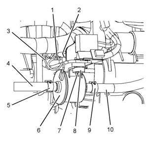
Illustration 1 |
|
g03342128 |
|
NOTICE |
|
3. Compress hose clamp (5) and slide the hose |
|
Care must be taken to ensure that fluids are con- tained during performance of inspection, mainte- nance, testing, adjusting and repair of the product. Be prepared to collect the fluid with suitable containers before opening any compartment or disassembling any component containing fluids. |
|
clamp away from fuel priming pump (6). |
|
4. Disconnect hose (4) from fuel priming pump (6). |
|
5. Plug hose (4) and cap fuel priming pump (6) immediately. |
|
Dispose of all fluids according to local regulations and mandates. |
|
6. Compress hose clamp (9) and slide the hose clamp away from fuel priming pump (6). |
|
7. Disconnect hose (10) from fuel priming pump (6). |
|
1. Turn the battery disconnect switch to the OFF |
|
position. |
|
8. Plug hose (10) and cap fuel priming pump (6) |
|
immediately. |
|
2. Turn the fuel supply to the OFF position. |
|
9. Disconnect harness assembly (1) from engine harness assembly (2) (not shown). |
|
10. Remove the nuts and bolts (7) from fuel priming pump (6). Support the fuel priming pump as the nuts and bolts are removed |
|
11. Remove fuel priming pump (6) from bracket (3). |
|
12. If necessary, remove isolators (8) from fuel priming pump (6). |
|
This document is printed from SPI². Not for RESALE |
![]()
![]()
![]()
![]()
![]()
![]()
![]()
|
6 |
|
KENR9145 |
|
Disassembly and Assembly Section |
|
1. Ensure that the fuel priming pump and bracket are free from wear or damage. Replace any components that are worn or damaged. |
|
2. Clean the gasket surfaces of the cylinder block and the bracket. |
|
Illustration 2 |
|
g03342129 |
|
13. If necessary, follow Step 13.a. through Step 3.g. in order to remove bracket (3). |
|
a. b. c. |
|
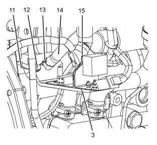
Position bracket (15) for the engine wiring harness assemblies away from bracket (3). |
|
Illustration 3 |
|
g03342129 |
|
Compress hose clamp (13) and slide along hose (14). |
|
3. If necessary, follow Step 3.a. through Step 3.g. in order to install bracket (3). |
|
Disconnect hose (14) from the connection on bracket (3). |
|
a. |
|
Position a new gasket (11) (not shown) onto the cylinder block. |
|
d. e. f. |
|
Remove bolts (12) from bracket (3). Remove bracket (3) from the cylinder block. Remove gasket (11) (not shown). |
|
b. c. d. |
|
Position bracket (3) to the cylinder block. Install bolts (12) to bracket (3) hand tight. |
|
Tighten bolts (12) to a torque of 10 N·m (89 lb in). |
|
InstallationProcedure |
|
e. f. |
|
Connect hose (14) to the connection on bracket (3). |
|
NOTICE Keep all parts clean from contaminants. |
|
Contaminants may cause rapid wear and shortened component life. |
|
Compress hose clamp (13) and slide along hose (14) toward the bracket. Ensure that the hose clamp is correctly positioned. |
|
NOTICE |
|
g. |
|
Position bracket (15) for the engine wiring harness assemblies away onto bracket (3). Ensure that the bracket for the engine wiring harness assemblies is correctly orientated. |
|
Care must be taken to ensure that fluids are con- tained during performance of inspection, mainte- nance, testing, adjusting and repair of the product. Be prepared to collect the fluid with suitable containers before opening any compartment or disassembling any component containing fluids. |
|
Dispose of all fluids according to local regulations and mandates. |
|
This document is printed from SPI². Not for RESALE |
![]()
![]()
![]()
![]()
![]()
![]()
![]()
![]()
![]()
|
KENR9145 |
|
7 |
|
Disassembly and Assembly Section |
|
17. Remove the air from the fuel system. Refer to Operation and Maintenance Manual, “Fuel System - Prime” for the correct procedure. |
|
i05240936 |
|
Fuel Priming Pump - Remove and Install (Electrical Fuel Priming Pump for 403F-15T Engines) |
|
Removal Procedure |
|
NOTICE Keep all parts clean from contaminants. |
|
Contaminants may cause rapid wear and shortened component life. |
|
Illustration 4 |
|
g03342128 |
|
4. If necessary, install isolators (8) to fuel priming pump (6). |
|
NOTICE |
|
Care must be taken to ensure that fluids are con- tained during performance of inspection, mainte- nance, testing, adjusting and repair of the product. Be prepared to collect the fluid with suitable containers before opening any compartment or disassembling any component containing fluids. |
|
5. Position fuel priming pump (6) onto bracket (3). |
|
6. Install the nuts and bolts (7) to fuel priming pump (6). Support the fuel priming pump as the nuts and bolts are installed |
|
Dispose of all fluids according to local regulations and mandates. |
|
7. Tighten the nuts and bolts (7) to a torque of 10 N·m |
|
(89 lb in). |
|
1. Turn the battery disconnect switch to the OFF position. |
|
8. Remove the plug from hose (10) and cap from fuel priming pump (6). |
|
2. Turn the fuel supply to the OFF position. |
|
9. Connect hose (10) to fuel priming pump (6). |
|
10. Compress hose clamp (9) and slide the hose clamp along hose (10). Ensure that the hose clamp is correctly positioned. |
|
11. Remove the plug from hose (4) and the cap from fuel priming pump (6). |
|
12. Connect hose (4) to fuel priming pump (6). |
|
13. Compress hose clamp (5) and slide the hose clamp along hose (4). Ensure that the hose clamp is correctly positioned. |
|
14. Connect harness assembly (1) to engine harness assembly (2) (not shown). |
|
15. Turn the fuel supply to the ON position. |
|
16. Turn the battery disconnect switch to the ON position. |
|
This document is printed from SPI². Not for RESALE |
![]()
![]()
![]()
![]()
![]()
![]()
![]()
|
8 |
|
KENR9145 |
|
Disassembly and Assembly Section |
|
Illustration 5 |
|
g03342666 |
|
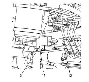
Illustration 6 |
|
g03342667 |
|
Typical example |
|
13. If necessary, follow Step 13.a. through Step 13.c. |
|
3. Compress hose clamp (5) and slide the hose |
|
in order to remove bracket (3). |
|
clamp away from fuel priming pump (6). |
|
a. |
|
Position bracket (11) for the engine wiring harness assemblies away from bracket (3). |
|
4. Disconnect hose (4) from fuel priming pump (6). |
|
5. Plug hose (4) and cap fuel priming pump (6) immediately. |
|
b. c. |
|
Remove bolts (12) from bracket (3). |
|
Remove bracket (3) from the cylinder block. |
|
6. Compress hose clamp (9) and slide the hose clamp away from fuel priming pump (6). |
|
InstallationProcedure |
|
7. Disconnect hose (10) from fuel priming pump (6). |
|
NOTICE |
|
Keep all parts clean from contaminants. |
|
8. Plug hose (10) and cap fuel priming pump (6) immediately. |
|
Contaminants may cause rapid wear and shortened component life. |
|
9. Disconnect harness assembly (1) from engine |
|
harness assembly (2) (not shown). |
|
NOTICE |
|
Care must be taken to ensure that fluids are con- tained during performance of inspection, mainte- nance, testing, adjusting and repair of the product. Be prepared to collect the fluid with suitable containers before opening any compartment or disassembling any component containing fluids. |
|
10. Remove the nuts and bolts (7) from fuel priming pump (6). Support the fuel priming pump as the nuts and bolts are removed |
|
11. Remove fuel priming pump (6) from bracket (3). |
|
12. If necessary, remove isolators (8) from fuel priming pump (6). |
|
Dispose of all fluids according to local regulations and mandates. |
|
1. Ensure that the fuel priming pump and bracket are free from wear or damage. Replace any components that are worn or damaged. |
|
This document is printed from SPI². Not for RESALE |
![]()
![]()
![]()
![]()
![]()
![]()
![]()
![]()
![]()
|
KENR9145 |
|
9 |
|
Disassembly and Assembly Section |
|
3. If necessary, install isolators (8) to fuel priming pump (6). |
|
4. Position fuel priming pump (6) onto bracket (3). |
|
5. Install the nuts and bolts (7) to fuel priming pump (6). Support the fuel priming pump as the nuts and bolts are installed |
|
6. Tighten the nuts and bolts (7) to a torque of 10 N·m (89 lb in). |
|
7. Remove the plug from hose (10) and cap from fuel priming pump (6). |
|
8. Connect hose (10) to fuel priming pump (6). |
|
9. Compress hose clamp (9) and slide the hose clamp along hose (10). Ensure that the hose clamp is correctly positioned. |
|
10. Remove the plug from hose (4) and the cap from |
|
Illustration 7 |
|
g03342667 |
|
fuel priming pump (6). |
|
2. If necessary, follow Step 2.a. through Step 2.d. in |
|
11. Connect hose (4) to fuel priming pump (6). |
|
order to install bracket (3). |
|
12. Compress hose clamp (5) and slide the hose clamp along hose (4). Ensure that the hose clamp is correctly positioned. |
|
a. b. c. |
|
Position bracket (3) onto the cylinder block. Install bolts (12) to bracket (3) hand tight. |
|
13. Connect harness assembly (1) to engine harness assembly (2) (not shown). |
|
Tighten bolts (12) to a torque of 25 N·m (221 lb in). |
|
14. Turn the fuel supply to the ON position. |
|
d. |
|
Position bracket (11) for the engine wiring harness assemblies away onto bracket (3). Ensure that the bracket for the engine wiring harness assemblies is correctly orientated. |
|
15. Turn the battery disconnect switch to the ON position. |
|
16. Remove the air from the fuel system. Refer to Operation and Maintenance Manual, “Fuel System - Prime” for the correct procedure. |
|
i05177851 |
|
Fuel Filter Base - Remove and Install (Fuel Filter Base for 403F-15T, 404F-22, and 404F-22T Engines) |
|
Removal Procedure |
|
NOTICE |
|
Do not allow dirt to enter the fuel system. Thoroughly clean the area around a fuel system component that will be disconnected. Fit a suitable cover over discon- nected fuel system component. |
|
Illustration 8 |
|
g03342666 |
|
Typical example |
|
This document is printed from SPI². Not for RESALE |