 English
 Espaol
 Franais
 阿拉伯
阿拉伯 中文
中文 Deutsch
 Italiano
 Português
 日本
日本 韩国
韩国 български
 hrvatski
 esky
esky Dansk
Dansk Nederlands
 suomi
suomi Ελληνικ
 印度
印度 norsk
norsk Polski
 Roman
Roman русский
 Svenska
Perkins珀金斯850-854F柴油发动机T411888排气岐管供应商,Perkins珀金斯850-854F柴油发动机T411888排气岐管技术价格规格咨询服务,Perkins珀金斯850-854F柴油发动机T411888排气岐管零配件供应,Perkins珀金斯850-854F柴油发动机T411888排气岐管售后服务中心,Perkins珀金斯850-854F柴油发动机T411888排气岐管,Perkins珀金斯850-854F柴油发动机T411888排气岐管详细的技术参数,

产品中心
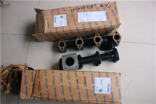
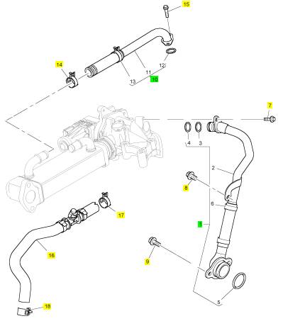
Perkins珀金斯850-854F柴油发动机T411888排气岐管
详细描述
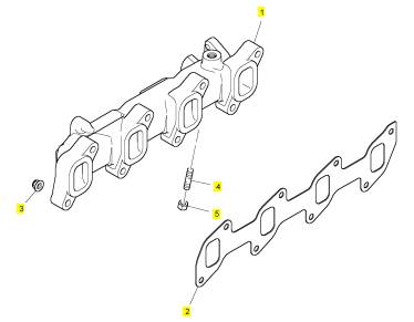
项目 零配件号码 最新件号 描述
1 T411888 1 T411888 排出岐管
2 T412083 1 T412083 密合垫 - 排出岐管
3 T412747 8 T412747 螺帽
4 T412750 2 T412750 图钉
5 T412745 2 T412745 螺帽
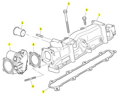
项目 零配件号码 最新件号 描述
1 T415861 1 T415861 进气岐管
2 T412726 1 T412726 管
3 T412065 1 T412065 密合垫
4 T412314 2 T412314 螺旋
5 2314 H020 5 2314 H020 螺旋
6 T412733 2 T412733 图钉
7 T412727 1 T419823 阀
8 T411920 1 T411920 密合垫
9 T412725 2 T412725 图钉
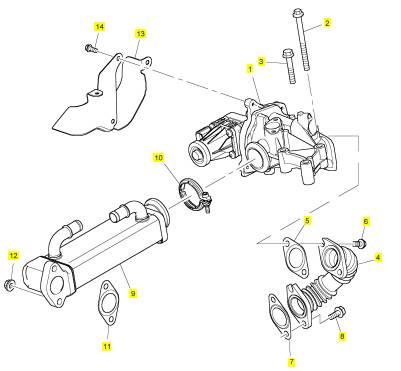
项目 零配件号码 最新件号 描述
1 T418298 1 T419490 以计量器计量阀
1 T412765 1 T419490 以计量器计量阀
1 T413717 1 T419490 以计量器计量阀
2 2314 H019 2 2314 H019 螺旋
3 T412253 1 T412253 螺拴
4 T415118 1 T415118 管
4 T412051 1 T415118 管
5 T412771 1 T412771 密合垫 -排气
6 T412172 2 T412172 螺旋
7 T412771 1 T412771 密合垫 -排气
8 T412358 2 T412358 螺拴
9 T412824 1 T412824 热交换器
10 T411911 1 T411911 砂箱夹
11 T412771 1 T412771 密合垫 -排气
12 2318 A603 2 2318 A603 螺帽
13 T412767 1 T412767 HEATSHIELD
14 2314 F003 3 2314 F003 螺旋
项目 零配件号码 最新件号 描述
1 T412823 1 T412823 管 -冷却器
7 2314 F005 1 2314 F005 螺旋
8 2314 H001 1 2314 H001 螺旋
8 T412170 1 T412170 水管夹
9 T412358 2 T412358 螺拴
10 T412782 1 T412782 管 -冷却器
14 T412170 1 T412170 水管夹
15 2314 F005 2 2314 F005 螺旋
16 T414851 1 T414851 管 -冷却器
16 T412802 1 T414851 管 -冷却器
17 T412170 1 T412170 水管夹
18 T412170 1 T412170 水管夹
|
General information |
|
1 |
|
Introduction |
|
This Workshop Manual has been written to provide the trained technician with enough information to service and overhaul all of the latest Perkins 100 Series engines. It has been compiled for use in conjunction with normal workshop practice and information contained in current service bulletins. Certain accepted practices have been purposely omitted in order to avoid repetition. For overhaul procedures the assumption is made that the engine is removed from the application. |
|
How to use this manual |
|
This manual is illustration based and is divided into 16 chapters. The illustrations in each chapter follow the sequence for the complete dismantle of a particular assembly or component. Assembly is achieved by the use of the illustrations in reverse order from the rear of the chapter. In assembly and inspection, all parts are to be thoroughly cleaned, lubricated, and where present, burrs and scale to be removed. Any open ports of high precision components, e.g. fuel injection equipment that are exposed when dismantled, must be blanked off until assembly, to prevent the ingress of foreign matter. |
|
Where the information applies to certain types of engine only, this is indicated in the illustrations. When set screws are fitted in "through" holes into the cylinder block, a suitable sealant should be used. In this manual, when the "left" or "right" of the engine is referred to, it is that side of the engine when viewed from the flywheel end. |
|
Special tools have been made available and a list of these is given in Chapter 16. At the start of each operation reference to the relevant special tools is made. |
|
POWERPART consumable products are listed on page 5. At the start of each operation reference to the necessary consumable products is made. |
|
Data and dimensions are provided as part of each operation and also in Chapter 2. Always use the full engine number to order new parts. |
|
Read and remember the "Safety precautions" on page 2. They are given for your protection and must be used at all times. |
|
Danger is indicated in the text by two methods: |
|
Warning! This indicates that there is a possible danger to the person. Caution: This indicates that there is a possible danger to the engine. Note: Is used where the information is important, but there is not a danger. |
|
Workshop Manual, TPD 1377E, issue 4 |
|
1 |
|
This document has been printed from SPI². Not for Resale |
![]()
![]()
|
1 |
|
100 Series |
|
Safety precautions |
|
These safety precautions are important. You must refer also to the local regulations in the country of use. Some items only refer to specific applications. |
|
Only use these engines in the type of application for which they have been designed. Do not change the specification of the engine. |
|
Do not smoke when you put fuel in the tank. |
|
Clean away any fuel which has been spilt. Material which has been contaminated by fuel must be moved to a safe place. |
|
Do not put diesel fuel in the tank during engine operation (unless absolutely necessary). |
|
Do not clean, add lubricating oil, or adjust the engine during operation (unless you have had the correct training; even then extreme caution must be used to prevent injury). |
|
Do not make any adjustments you do not understand. |
|
Ensure the engine does not run in a location where it can cause a concentration of toxic emissions. Other persons must be kept at a safe distance whilst the engine and auxiliary equipment is in operation. Do not permit loose clothing or long hair near parts which move. |
|
Keep away from moving parts during engine operation. |
|
Warning! Some parts cannot be seen clearly while the engine is running. |
|
Do not run the engine with any safety guards removed. |
|
Do not remove the filler cap or any component of the cooling system whilst the engine is hot and while the coolant is under pressure, because dangerous hot coolant can be discharged. |
|
Do not use salt water in the fresh water cooling system or any other coolant which can cause corrosion. |
|
Do not allow sparks or fire near the batteries (especially during charging), as the gases from the electrolyte are highly flammable. The battery fluid can burn and is also dangerous to the skin and especially the eyes. |
|
Disconnect the battery terminals before you make a repair to the electrical system. |
|
Only one person must be in control of the engine. Ensure the engine is only operated from the control panel or operator's position. |
|
If your skin comes into contact with high pressure fuel, get medical assistance immediately. |
|
Diesel fuel and used engine oils can cause skin damage to some persons. Use protection on the hands (gloves or special protection solutions). |
|
Do not move equipment unless the brakes are in good condition. Do not use ether or other starting fluids to start these engines. |
|
Do not wear clothing which is contaminated by lubricating oil. |
|
Do not put material which is contaminated with oil into the pockets of clothing. Discard used lubricating oil in a safe place to prevent contamination. Use extreme care if emergency repairs must be made in adverse conditions. |
|
The combustible material of some components of the engine can be extremely dangerous if burnt. Never let this material come into contact with skin or the eyes. Refer to "Viton seals" on page 11. |
|
Do not allow compressed air to contact the skin. If compressed air enters the skin seek medical help immediately. |
|
Always use a safety cage to protect the operator when a component is to be pressure tested in a container of water. Fit safety wires to secure the plugs which seal the hose connections of a component which is to be pressure tested. |
|
Do not clean an engine whilst it is running. If cold cleaning fluids are applied to a hot engine, certain components on the engine may be damaged. |
|
Continued |
|
2 |
|
Workshop Manual, TPD 1377E, issue 4 |
|
This document has been printed from SPI². Not for Resale |
![]()
![]()
![]()
![]()
![]()
![]()
![]()
![]()
![]()
![]()
![]()
![]()
![]()
![]()
![]()
![]()
![]()
![]()
![]()
![]()
![]()
![]()
![]()
![]()
![]()
![]()
![]()
![]()
![]()
|
1 |
|
100 Series |
|
Ensure that the control lever of the transmission drive is in the "out of drive" position before the engine is started. |
|
Read and use the instructions relevant to "Engine lift equipment" on page 10. |
|
Do not use more than 50% anti freeze concentration by volume at high ambients, otherwise engine damage will result. |
|
Fit only genuine Perkins Parts. |
|
Workshop Manual, TPD 1377E, issue 4 |
|
3 |
|
This document has been printed from SPI². Not for Resale |
![]()
![]()
![]()
![]()
![]()
![]()
|
1 |
|
100 Series |
|
Engine preservation |
|
Introduction |
|
The recommendations indicated below are designed to prevent damage to the engine when it is withdrawn from service for a prolonged period. Use these procedures after the engine is withdrawn from service. The instructions for the use of POWERPART products are given on the outside of each container. |
|
Procedure |
|
1 Completely clean the outside of the engine. |
|
2 When a preservative fuel is to be used, drain the fuel system and fill it with the preservative fuel. POWERPART Lay-Up 1 can be added to the normal fuel to change it to a preservative fuel. If preservative fuel is not used, the system can be completely filled with normal fuel but the fuel must be drained and discarded at the end of the storage period together with the fuel filter canister. |
|
3 Operate the engine until it is warm. Then correct leakages of fuel, lubricating oil or air. Stop the engine and drain the lubricating oil from the sump. |
|
4 Renew the canister of the lubricating oil filter. |
|
5 Fill the sump to the full mark with new and clean lubricating oil and add POWERPART Lay-up 2 to the oil to protect the engine against corrosion. If POWERPART Lay-Up 2 is not available, use a correct preservative fluid instead of the lubricating oil. If a preservative fluid is used, this must be drained and the lubricating oil sump must be filled to the correct level with normal lubricating oil at the end of the storage period. |
|
6 Drain the coolant circuit, In order to protect the cooling system against corrosion, fill it with an approved antifreeze mixture because this gives protection against corrosion. |
|
Caution: Certain corrosion inhibitor mixtures could cause damage to some engine components. It is recommended that you consult the Perkins Service Department, Peterborough. |
|
7 Operate the engine for a short period in order to circulate the lubricating oil and the coolant in the engine. |
|
8 Disconnect the battery. Then put the battery into safe storage in a fully charged condition. Before the battery is put into storage, protect its terminals against corrosion. POWERPART Lay-Up 3 can be used on the terminals. |
|
9 Clean the engine breather pipe (if one is fitted) and seal the end of the pipe. |
|
10 Remove the atomisers and spray POWERPART Lay-Up 2 for one to two seconds into each cylinder bore with the piston at BDC. |
|
Slowly turn the crankshaft one revolution and then fit the atomisers, complete with new seat washers. |
|
11 Remove the air filter. Then, if necessary, remove the pipe installed between the air filter and the induction manifold. Release the cap screws and remove the rocker cover. Spray POWERPART Lay-Up 2 around the rocker shaft assembly and into the induction ports in the cylinder head, as indicated on the container label. Fit the rocker cover. Seal the manifold with waterproof tape. |
|
12 Remove the exhaust pipe. Spray POWERPART Lay-Up 2 into the exhaust manifold. Seal the manifold with waterproof tape. |
|
13 Seal the vent pipe of the fuel tank or the fuel filler cap with waterproof tape. 14 Remove the alternator drive belt and put it into storage. |
|
15 In order to prevent corrosion, spray the engine with POWERPART Lay-Up 3. Do not spray the area inside the alternator cooling fan. |
|
Caution: After a period in storage, but before the engine is started, operate the starter motor with the stop switch held in the "STOP" position until oil pressure is indicated. Oil pressure is indicated when the low pressure warning light is extinguished. If a solenoid stop control is used on the fuel injection pump, it must be disconnected for this operation. |
|
If the engine protection is done correctly according to the above recommendations, no corrosion damage will normally occur. Perkins are not responsible for damage which may occur when an engine is in storage after a period in service. |
|
4 |
|
Workshop Manual, TPD 1377E, issue 4 |
|
This document has been printed from SPI². Not for Resale |