 English
 Espaol
 Franais
 阿拉伯
阿拉伯 中文
中文 Deutsch
 Italiano
 Português
 日本
日本 韩国
韩国 български
 hrvatski
 esky
esky Dansk
Dansk Nederlands
 suomi
suomi Ελληνικ
 印度
印度 norsk
norsk Polski
 Roman
Roman русский
 Svenska
Perkins珀金斯850柴油机26510343空气过滤器供应商,Perkins珀金斯850柴油机26510343空气过滤器技术价格规格咨询服务,Perkins珀金斯850柴油机26510343空气过滤器零配件供应,Perkins珀金斯850柴油机26510343空气过滤器售后服务中心,Perkins珀金斯850柴油机26510343空气过滤器,Perkins珀金斯850柴油机26510343空气过滤器详细的技术参数,

产品中心
Perkins珀金斯850柴油机26510343空气过滤器
详细描述
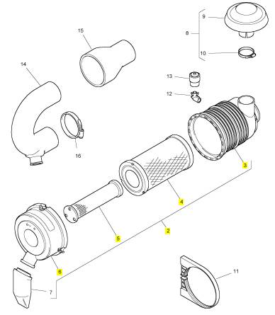
项目 零配件号码 最新件号 描述
2 1 体
3 26510342 1 26510342 主空气过滤器
4 26510343 1 26510343 安全空气过滤器
5 26510326 1 26510326 盖
6 26510327 1 26510327 阀
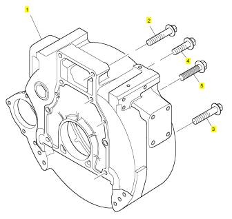
项目 零配件号码 最新件号 描述
1 T415115 1 T415115 飞轮壳
2 2314 J712 2 2314 J712 螺旋
3 2314 J710 4 2314 J710 螺旋
4 2314 J706 2 2314 J706 螺旋
5 T411324 2 T411324 螺旋
|
Viton seals |
|
Some seals used in engines and in components fitted to engines are made of Viton. |
|
Viton is used by many manufacturers and is a safe material under normal conditions of operation. |
|
If Viton is burned, a product of this burnt material is an acid which is extremely dangerous. Never allow this burnt material to come into contact with the skin or with the eyes. |
|
If it is necessary to come into contact with components which have been burnt, ensure that the precautions which follow are used: |
|
Ensure that the components have cooled. |
|
Use neoprene gloves and discard the gloves safely after use. |
|
Wash the area with calcium hydroxide solution and then with clean water. Disposal of components and gloves which are contaminated must be in accordance with local regulations. |
|
Warning! If there is contamination of the skin or eyes, wash the affected area with a continuous supply of clean water or with calcium hydroxide solution for 15-60 minutes. Obtain immediate medical attention. |
|
Safety cautions, when an engine is cleaned |
|
Care should be taken, when an engine is cleaned with the use of a high pressure hose. |
|
Cautions: |
|
Do not wash an engine while the engines runs or if it is hot. If cold cleaning fluids are applied to a hot engine, certain components on the engine could be damaged. |
|
Leave the engine to cool for at least one hour and disconnect the battery connections before cleaning. |
|
Do not wash any part of the Fuel Injection Pump (FIP), glow plugs, electrical shut off solenoid (ESOS) or electrical connectors. |
|
Ensure that the alternator, starter motor and any other electrical components are shielded and not directly cleaned by the high pressure cleaning system. |
|
If these cautions are ignored, the engine or certain components of the engine could be damaged, fail to operate and also make the manufacturer’s warranty invalid. |
|
Engines that conform to Emissions Levels |
|
Engines that are fitted with an emissions label on the timing case conform to stage 1 emissions legislation and, for certain service procedures, additional information is included to ensure that the engine remains emissions approved. |
|
Workshop Manual, TPD 1377E, issue 4 |
|
11 |
|
This document has been printed from SPI². Not for Resale |
![]()
![]()
![]()
![]()
![]()
![]()
![]()
![]()
![]()
![]()
|
1 |
|
100 Series |
|
Compression test data |
|
Tests have shown that many factors affect compression pressures. Battery, starter motor condition, ambient conditions and the type of gauge used can give a wide variation of results for a given engine. |
|
Pressure kPa (lbf/in²) Engine model |
|
Standard |
|
To be repaired <2450 (355.5) <2450 (355.5) |
|
102-05, 103-07, 103-10, 103-13 103-15, 104-19, 104-22 |
|
>2940 (426.6) @ 200 rev/min >2940 (426.6) @ 250 rev/min |
|
A compression test should only be used to compare between cylinders of an engine. If one or more cylinders vary by more than 350 KPa (50 lbf/in²) then those cylinders may be faulty. |
|
A compression test should not be the only method used to show the condition of an engine, but it should be used together with other symptoms and tests. |
|
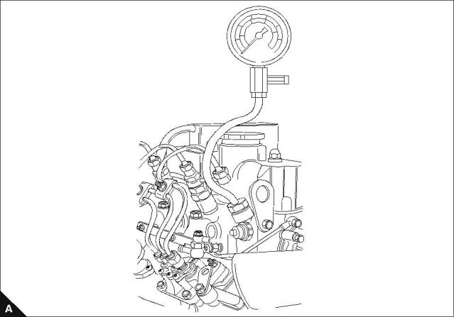
How to do a compression test |
|
Note: Before the compression test, ensure that the battery is in good condition and that it is fully charged. Also ensure that the starter motor is in good condition. |
|
1 To ensure that the engine cannot start, disconnect the engine stop solenoid or ensure the engine stop control is in the ‘stop’ position. |
|
2 Ensure that the valve tip clearances are set correctly. 3 Remove the atomisers. |
|
4 Fit a suitable gauge into the atomiser hole of the cylinder to be tested. 5 Operate the starter motor and record the pressure indicated on the gauge. 6 Repeat for each cylinder. |
|
12 |
|
Workshop Manual, TPD 1377E, issue 4 |
|
This document has been printed from SPI². Not for Resale |
![]()
![]()

|
100 Series |
|
2 |
|
Specifications |
|
2 |
|
Basic engine data |
|
Engine model Engine build code Number of cylinders |
|
102-05 KN |
|
103-07 |
|
103-10 KD |
|
103-13 KH |
|
103-15 KE |
|
104-19 |
|
104-22 KR |
|
KL 3 |
|
KF 4 |
|
2 |
|
3 |
|
3 |
|
3 |
|
4 |
|
Cylinder |
|
arrangement and cycle |
|
Vertical in line, four stroke cycle |
|
Direction of rotation Induction system Combustion system Nominal bore |
|
Clockwise, viewed from front Naturally aspirated |
|
IDI special swirl |
|
67 mm (2.6 in) |
|
67 mm (2.6 in) |
|
75 mm (2.9 in) |
|
84 mm (3.3 in) |
|
84 mm (3.3 in) |
|
84 mm (3.3 in) |
|
84 mm (3.3 in) |
|
64 mm (2.5 in) |
|
64 mm (2.5 in) |
|
72 mm (2.8 in) |
|
80 mm (3.1 in) |
|
90 mm (3.5 in) |
|
90 mm (3.5 in) |
|
100 mm (3.9 in) |
|
Stroke |
|
Compression ratio |
|
24:1 |
|
24:1 |
|
23:1 |
|
22:1 |
|
22.5:1 |
|
22:1 |
|
22:1 |
|
0,451 ltrs. (27.5 in³) |
|
0,676 ltrs. (41.2 in³) |
|
0,954 ltrs. (58.2 in³) |
|
1,330 ltrs. (81.1 in³) |
|
1,496 ltrs. (91.2 in³) |
|
1,995 ltrs. (121.7 in³) |
|
2,216 ltrs. (135.2 in³) |
|
Cubic capacity Firing order |
|
1, 2 |
|
1, 2, 3 |
|
1, 2, 3 |
|
1, 2, 3 |
|
1, 2, 3 |
|
1, 3, 4, 2 |
|
1, 3, 4, 2 |
|
352-448 KPa |
|
Oil pressure relief Oil pressure switch |
|
262-359 KPa |
|
29,6 KPa |
|
Valve tip clearance (cold) |
|
0,2 mm (0.0078 in) |
|
-Inlet |
|
0,2 mm (0.0078 in) |
|
-Exhaust |
|
Electrical system Governor |
|
12 volt |
|
Mechanical all speed |
|
Fuel injection |
|
Cassette type fuel injection system |
|
Workshop Manual, TPD 1377E, issue 4 |
|
13 |
|
This document has been printed from SPI². Not for Resale |
![]()
![]()

|
2 |
|
100 Series |
|
Thread Sealant |
|
When setscrews or studs are fitted into holes which are tapped through the cylinder block, a suitable sealant must be used to prevent leakage. |
|
Micro encapsulated anaerobic sealant (M.E.A.S) fasteners have been introduced instead of jointing compounds or other sealants when the fasteners are fitted in through holes into oil or coolant passages. The identification of these fasteners, as supplied, is by a red, blue, or other colour sealant around the fastener threads. |
|
With M.E.A.S. sealed studs, the sealed end must be fitted into the cylinder head / cylinder block etc. Ensure that the threaded holes have a 1,59 mm (0.0625 in) 45° chamfer, to ensure that when the new fasteners are fitted the M.E.A.S. sealant is not removed. If the fasteners have to be removed and fitted again, the threads must be cleaned and a suitable sealant used. |
|
Note: New setscrews have sealant applied by the manufacturer to the first 13,0 mm (0.50 in) of the threads. If the setscrews are to be used again, clean the old sealant from the male and female threads and apply new sealant, (Powerpart Threadlock and Nutlock) to the setscrews. |
|
Recommended torque tensions |
|
Most of the torques on the engine are standard. Torques specific to individual operations are listed in the relevant operation. The standard torques listed in the tables below can be used when a specific torque is not necessary. |
|
Note: The torques below apply to components lubricated lightly with clean engine oil before they are fitted. |
|
Standard torques for setscrews, studs and nuts |
|
Coarse Screw Thread |
|
Fine Screw Thread |
|
Thread size |
|
Bolt Strength |
|
Pitch (mm) |
|
Torque (Nm) |
|
Torque (lbf ft) |
|
Torque (kgf m) |
|
Pitch (mm) |
|
Torque (Nm) |
|
Torque (lbf ft) |
|
Torque (kgf m) |
|
8.8 11T |
|
3 4 |
|
2 3 |
|
0,3 0,4 |
|
M4 M5 |
|
0,7 0,8 |
|
8.8 11T |
|
6 8 |
|
4 6 |
|
0,6 0,8 |
|
8.8 11T |
|
10 14 |
|
7 10 |
|
1,0 1,4 |
|
M6 |
|
1,0 |
|
8.8 11T |
|
26 32 |
|
19 24 |
|
2,7 3,3 |
|
30 35 |
|
22 26 |
|
3,0 3,6 |
|
M8 |
|
1,25 1,5 |
|
1,0 1,25 1,25 1,5 |
|
8.8 11T |
|
50 62 |
|
37 46 |
|
5,1 6,3 |
|
56 66 |
|
41 49 |
|
5,7 6,7 |
|
M10 M12 M14 M16 |
|
8.8 11T |
|
75 104 |
|
55 77 |
|
7,6 10,6 |
|
84 113 |
|
62 83 |
|
8,6 11,5 |
|
1,75 2,0 |
|
8.8 11T |
|
118 157 |
|
87 116 |
|
12,0 16,0 |
|
132 167 |
|
97 123 |
|
13,5 17,0 |
|
8.8 11T |
|
167 230 |
|
123 170 |
|
17,0 23,4 |
|
175 245 |
|
129 181 |
|
17,8 20,5 |
|
2,0 |
|
1,5 |
|
Examples of applicable material |
|
Bolt |
|
Example Strength |
|
8.8 |
|
S45C |
|
11T |
|
SCM435 |
|
14 |
|
Workshop Manual, TPD 1377E, issue 4 |
|
This document has been printed from SPI². Not for Resale |