English
 Espaol
 Franais
 阿拉伯
阿拉伯 中文
中文 Deutsch
 Italiano
 Português
 日本
日本 韩国
韩国 български
 hrvatski
 esky
esky Dansk
Dansk Nederlands
 suomi
suomi Ελληνικ
 印度
印度 norsk
norsk Polski
 Roman
Roman русский
 Svenska
Perkins珀金斯850-854F柴油发动机T416398空气过滤器供应商,Perkins珀金斯850-854F柴油发动机T416398空气过滤器技术价格规格咨询服务,Perkins珀金斯850-854F柴油发动机T416398空气过滤器零配件供应,Perkins珀金斯850-854F柴油发动机T416398空气过滤器售后服务中心,Perkins珀金斯850-854F柴油发动机T416398空气过滤器,Perkins珀金斯850-854F柴油发动机T416398空气过滤器详细的技术参数,

产品中心
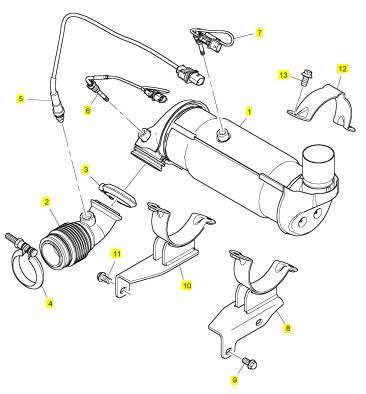
Perkins珀金斯850-854F柴油发动机T416398空气过滤器
详细描述
项目 零配件号码 最新件号 描述
1 T416398 1 T416398 空气过滤器总成
2 T416396 1 T416396 手风箱
3 T412084 1 T412084 砂箱夹
4 T412084 1 T412084 砂箱夹
5 T413985 1 T413985 感应器
6 T413439 1 T413439 温度感应器
7 T413978 1 T413978 温度感应器
8 T416407 1 T416407 托架
9 T412519 2 T412519 螺旋
10 T416400 1 T416400 托架
11 T412519 2 T412519 螺旋
12 T416314 2 T416314 托架
13 T412343 4 T412343 螺旋
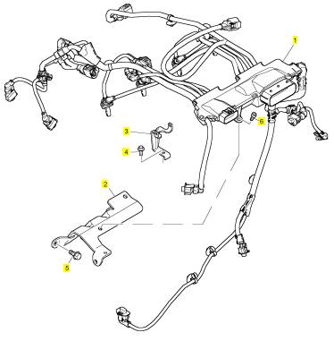
项目 零配件号码 最新件号 描述
1 T412691 1 T412691 线束
2 T411887 1 T411887 托架
3 T411896 2 T411896 托架
4 2314 F003 2 2314 F003 螺旋
5 T412358 3 T412358 螺拴
6 T411956 1 T411956 CAPSCREW
|
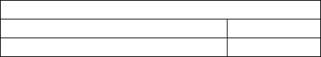
o remove and to fit |
|
Operation 3-8 |
|
Special requirements |
|
Torque Nm (lbf ft) kgf m |
|
102-05, 103-07, 103-10 |
|
11 (8) 1,1 12 (9) 1,2 |
|
103-13, 103-15, 104-19, 104-22 |
|
Notes: |
|
Be aware of the oil restriction in the banjo bolts (A1). |
|
The diagram below shows a typical arrangement only. |
|
1 |
|
32 |
|
Workshop Manual, TPD 1377E, issue 4 |
|
This document has been printed from SPI². Not for Resale |
![]()
![]()
![]()
![]()
![]()
![]()
|
3 |
|
100 Series |
|
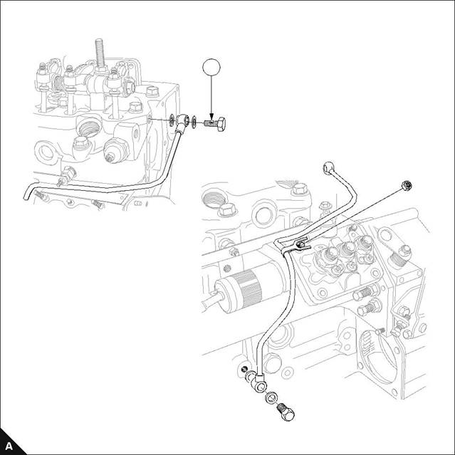
Atomisers |
|
To remove and to fit |
|
Operation 3-9 |
|
Special requirements |
|
Torque Nm (lbf ft) kgf m |
|
Test Pressure kgf/cm² (lbf/in²) ats |
|
102-05, 103-07 |
|
64 (47) 6,5 81 (60) 8,2 64 (47) 6,5 |
|
102-05, 103-07 |
|
120 (1707) 116 120 (1707) 116 150 (2133) 145 |
|
103-10 |
|
103-10 |
|
103-13, 103-15, 104-19, 104-22 |
|
103-13, 103-15, 104-19, 104-22 |
|
Cautions: |
|
Deep sockets should always be used during this procedure. Connections should be blanked off until assembly. |
|
Notes: |
|
Item (A1) is used on 103-10 engines only. |
|
For emissions approved engines. It is essential that the fuel adjustment screw is not altered from the original setting. |
|
For emissions approved engines. The maximum No Load Speed must be checked after assembly. |
|
103-13 103-15 104-19 104-22 |
|
102-05 103-07 103-10 |
|
1 |
|
Workshop Manual, TPD 1377E, issue 4 |
|
33 |
|
This document has been printed from SPI². Not for Resale |
![]()
![]()
![]()
![]()
![]()
![]()
![]()
![]()
![]()

|
3 |
|
100 Series |
|
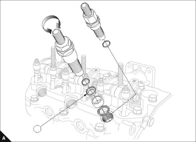
Busbar / glowplugs |
|
To remove and to fit |
|
Operation 3-10 |
|
Special requirements |
|
Torque Nm (lbf ft) kgf m |
|
Glowplugs Contacts |
|
17 (12) 1,7 17 (12) 1,7 |
|
Note: The diagram below shows a typical arrangement only. |
|
34 |
|
Workshop Manual, TPD 1377E, issue 4 |
|
This document has been printed from SPI². Not for Resale |
![]()
![]()
![]()
![]()
|
3 |
|
100 Series |
|
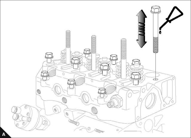
Head bolts |
|
To remove and to fit |
|
Operation 3-11 |
|
For recommended torques and tightening sequences refer to Operation 3-14. |
|
Notes: |
|
Lubricate bolts with engine lubricating oil. |
|
For emissions approved engines. It is essential that the fuel adjustment screw is not altered from the original setting. |
|
For emissions approved engines. The maximum No Load Speed must be checked after assembly. |
|
Workshop Manual, TPD 1377E, issue 4 |
|
35 |
|
This document has been printed from SPI². Not for Resale |
![]()
![]()
![]()
![]()
![]()
![]()
![]()
|
3 |
|
100 Series |
|
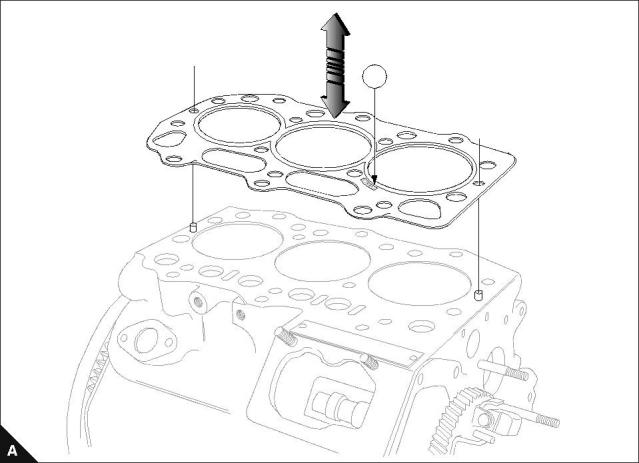
Cylinder head gasket |
|
To remove and to fit |
|
Operation 3-12 |
|
Align gasket on dowels, gasket must only be assembled with markings (A1) facing up. |
|
Notes: |
|
Always fit dry. |
|
For emissions approved engines. If the cylinder block, crankshaft, connecting rods or pistons are changed, the piston height must be checked and the correct thickness gasket used, refer to operation 3-13. |
|
1 |
|
36 |
|
Workshop Manual, TPD 1377E, issue 4 |
|
This document has been printed from SPI². Not for Resale |
![]()
![]()
![]()
![]()
![]()
![]()
|
3 |
|
100 Series |
|
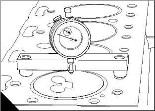
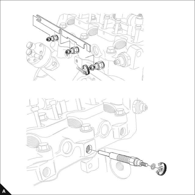
To select the correct thickness of cylinder head gasket |
|
Operation 3-13 |
|
Caution: If the correct piston height above or below the cylinder block is not obtained, damage to the engine can occur. The difference between the highest and the lowest piston height must not exceed 0.1 mm. |
|
1 Put the piston height tool (A) on the face of the cylinder block and rotate the gauge dial to the zero position. 2 Rotate the crankshaft until the piston crown is approximately at top dead centre (TDC). |
|
3 Carefully put the tool over the top of the piston with the plunger of the gauge in contact with the piston above the axis of the gudgeon pin. |
|
4 Rotate the crankshaft to ensure that the piston is at the highest position and make a note of the gauge indication. |
|
Notes: |
|
If the cylinder block, crankshaft, connecting rods or pistons are changed the piston height will have to be checked and the correct thickness gasket used. |
|
If the original piston is used, ensure that it is assembled to the correct connecting rod and is used in the original cylinder. |
|
Cylinder head gasket selection |
|
Engine |
|
Protrusion above cylinder block top face 0,45 to 0,55 mm |
|
Gasket thickness 1,1 mm |
|
103-10 |
|
0,56 to 0,65 mm |
|
1,2 mm |
|
0,66 to 0,75 mm |
|
1,3 mm |
|
103-13 103-15 |
|
0,60 to 0,70 mm |
|
1,3 mm |
|
0,71 to 0,80 mm |
|
1,4 mm |
|
0,50 to 0,60 mm |
|
1,2 mm |
|
104-19 Engine 102-05 |
|
0,61 to 0,70 mm |
|
1,3 mm |
|
Protrusion below cylinder block top face -0,30 to -0,15 mm |
|
Gasket thickness 0,5 mm |
|
-0,16 to +0,05 mm |
|
0,6 mm |
|
-0,40 to -0,25 mm |
|
0,4 mm |
|
103-07 104-22 |
|
-0,26 to -0,15 mm |
|
0,5 mm |
|
-0,45 to -0,30 mm |
|
0,4 mm |
|
-0,29 to -0,20 mm |
|
0,5 mm |
|
A |
|
H1044 |
|
Workshop Manual, TPD 1377E, issue 4 |
|
37 |
|
This document has been printed from SPI². Not for Resale |
![]()
![]()
![]()
![]()
![]()
![]()