 English
 Espaol
 Franais
 阿拉伯
阿拉伯 中文
中文 Deutsch
 Italiano
 Português
 日本
日本 韩国
韩国 български
 hrvatski
 esky
esky Dansk
Dansk Nederlands
 suomi
suomi Ελληνικ
 印度
印度 norsk
norsk Polski
 Roman
Roman русский
 Svenska
Perkins珀金斯850-854F柴油发动机T412885高压燃油泵供应商,Perkins珀金斯850-854F柴油发动机T412885高压燃油泵技术价格规格咨询服务,Perkins珀金斯850-854F柴油发动机T412885高压燃油泵零配件供应,Perkins珀金斯850-854F柴油发动机T412885高压燃油泵售后服务中心,Perkins珀金斯850-854F柴油发动机T412885高压燃油泵,Perkins珀金斯850-854F柴油发动机T412885高压燃油泵详细的技术参数,

产品中心
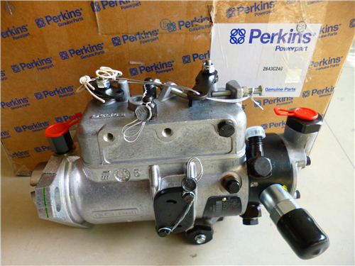
Perkins珀金斯850-854F柴油发动机T412885高压燃油泵
详细描述
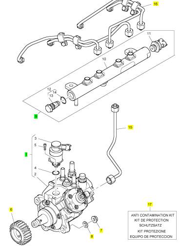
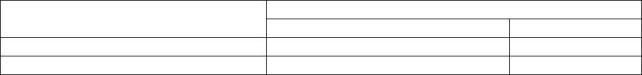
项目 零配件号码 最新件号 描述
1 T412885 1 T412885 高压燃油泵
6 T411955 1 T411955 燃料喷射泵传动机构
7 2318 A603 3 2318 A603 螺帽
8 2131 A008 3 2131 A008 垫圈
9 T412694 1 T412694 燃料轨条
15 T412367 1 T412367 以管输送 - HP 泵以横木围栏
16 T412055 1 T412055 管 - 燃料的喷射
17 T412504 1 T412504 保护总成
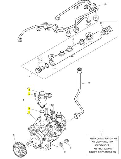
项目 零配件号码 最新件号 描述
2 1 高压燃油泵
3 T418288 1 T418288 调整阀
4 T418289 1 T418289 密封 - O 的圈
5 T418296 2 T418296 螺旋
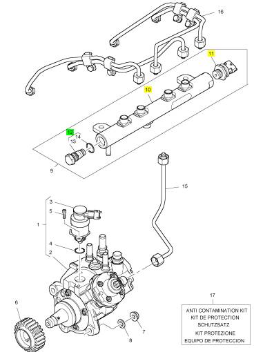
项目 零配件号码 最新件号 描述
10 1 燃料轨条
11 T415770 1 T415770 感应器
12 T415769 1 T415769 压力阀
|
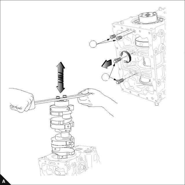
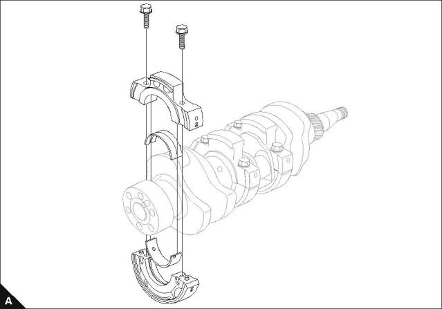
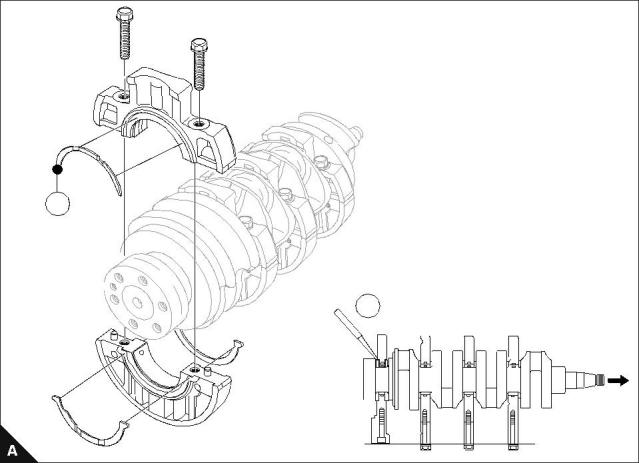
Crankshaft retainer setscrews and crankshaft |
|
To remove and to fit |
|
Operation 5-3 |
|
Special requirements |
|
Hex hole setscrews (A1) : Torque Nm (lbf ft) kgf m |
|
Hex setscrews (A2) : Torque Nm (lbf ft) kgf m |
|
102-05, 103-07, 103-10 |
|
27 (20) 2,7 27 (20) 2,7 |
|
102-05, 103-07, 103-10 |
|
27 (20) 2,7 51 (38) 5,2 |
|
103-13, 103-15, 104-19, 104-22 |
|
103-13, 103-15, 104-19, 104-22 |
|
Check that the oil ways of the bearings match up with the oil ways in the block. |
|
Caution: Before removal and fitting of the crankshaft ensure that the pressure relief valve has been removed. |
|
Notes: |
|
For emissions approved engines. The fuel adjustment screw must not be altered from the original setting. The maximum No Load Speed must be checked after assembly. If a new crankshaft is fitted, see Operation 3-13. |
|
Continued |
|
Workshop Manual, TPD 1377E, issue 4 |
|
59 |
|
This document has been printed from SPI². Not for Resale |
![]()
![]()
![]()
![]()
![]()
![]()
![]()

|
5 |
|
100 Series |
|
1 |
|
2 |
|
60 |
|
Workshop Manual, TPD 1377E, issue 4 |
|
This document has been printed from SPI². Not for Resale |
![]()
![]()
|
5 |
|
100 Series |
|
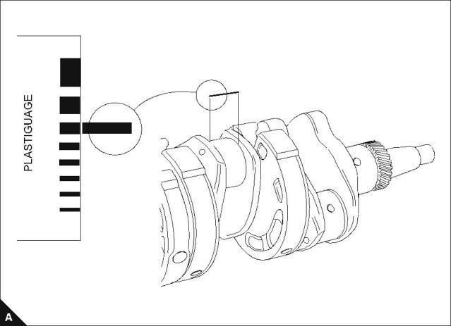
Bearing clearance |
|
To check |
|
Operation 5-4 |
|
Special requirements |
|
Clearance mm (in) |
|
Engine model |
|
Standard |
|
Service limit 0,20 (0.0079) 0,20 (0.0079) 0,20 (0.0079) |
|
102-05, 103-07 |
|
0,031 - 0,079 (0.00122 - 0.00311) 0,035 - 0,083 (0.00138 - 0.00327) 0,035 - 0,085 (0.00138 - 0.00335) |
|
103-10 |
|
103-13, 103-15, 104-19, 104-22 |
|
Use Plastigauge® to check the bearing clearance. |
|
Tighten the main bearings to the torque settings given in Operation 5-5 for two and three cylinder engines or Operation 5-6 for four cylinder engines. |
|
1.0 |
|
2.0 2.5 |
|
3.0 4.0 5.0 6.0 7.0 |
|
INCH |
|
Workshop Manual, TPD 1377E, issue 4 |
|
61 |
|
This document has been printed from SPI². Not for Resale |
![]()
![]()
![]()
![]()
|
5 |
|
100 Series |
|
Main bearings |
|
To dismantle and to assemble (two and three cylinder engines) |
|
Operation 5-5 |
|
Special requirements |
|
Bearing holder (Aluminium) : Thickness mm (in) |
|
Torque Nm (lbf ft) kgf m |
|
Standard |
|
Service limit |
|
102-05, 103-07, 103-10 Aluminium Bearings |
|
22 (16) 2,2 |
|
21,85 - 21,95 (0.8602 - 0.8641) |
|
21,6 (0.8503) |
|
102-05, 103-07, 103-10 Cast Iron Bearings |
|
27 (19.9) 2,7 |
|
N/A |
|
N/A |
|
End Float : Clearance mm (in) |
|
Engine model |
|
Standard |
|
Service limit 0,50 (0.0197) 0,50 (0.0197) |
|
102-05, 103-07 103-10 |
|
0,10 - 0,30 (0.0040 - 0.0120) 0,05 - 0,30 (0.0020 - 0.0120) |
|
1 Identify position of bearing carriers on shaft. |
|
2 Install bearing carriers on the crankshaft ensuring oil holes align with feed holes in cylinder block. 3 Check end float. |
|
4 Check number 2 bearing holder on 102-05 engines and number 3 bearing holder on 103-07 and 103-10 engines for wear, poor contact, look burnt or other defects. Defective bearing holders must be renewed. |
|
Notes: |
|
For emissions approved engines. The fuel adjustment screw must not be altered from the original setting. The maximum No Load Speed must be checked after assembly. |
|
62 |
|
Workshop Manual, TPD 1377E, issue 4 |
|
This document has been printed from SPI². Not for Resale |
![]()
![]()
![]()
![]()
![]()
![]()
|
5 |
|
100 Series |
|
To dismantle and to assemble (four cylinder engines) |
|
Operation 5-6 |
|
Special requirements Torque Nm (lbf ft) kgf m |
|
103-13, 103-15, 104-19, 104-22 |
|
51 (38) 5,2 |
|
End float : Clearance mm (in) |
|
Thrust washer : Thickness mm (in) |
|
Standard |
|
Service limit |
|
Standard |
|
Service limit |
|
0,10 - 0,40 (0.0040 - 0.0160) |
|
0,50 (0.0197) max |
|
2,95 - 3,00 (0.1161 - 0.1181) |
|
2,80 (0.1102) max |
|
1 Identify position of bearing carriers on shaft. |
|
2 Install bearing carriers on shaft ensuring oil holes align with feed holes in cylinder block. 3 Check end float clearance (A2). |
|
Note: Ensure that the thrust washers are aligned correctly, and are fitted with their oil grooves towards the crankshaft. |
|
4 Check the thrust washers for wear, poor contact, look burnt, or have any other defects. Defective washers must be renewed. |
|
Note: Item (A1) is only used on 104-19 and 104-22 engines. |
|
1 |
|
2 |
|
Workshop Manual, TPD 1377E, issue 4 |
|
63 |
|
This document has been printed from SPI². Not for Resale |
![]()
![]()
![]()
![]()
![]()

|
This page is intentionally blank |
|
This document has been printed from SPI². Not for Resale |