 English
 Espaol
 Franais
 阿拉伯
阿拉伯 中文
中文 Deutsch
 Italiano
 Português
 日本
日本 韩国
韩国 български
 hrvatski
 esky
esky Dansk
Dansk Nederlands
 suomi
suomi Ελληνικ
 印度
印度 norsk
norsk Polski
 Roman
Roman русский
 Svenska
Perkins珀金斯900 3.152柴油发动机37188571摇臂室盖供应商,Perkins珀金斯900 3.152柴油发动机37188571摇臂室盖技术价格规格咨询服务,Perkins珀金斯900 3.152柴油发动机37188571摇臂室盖零配件供应,Perkins珀金斯900 3.152柴油发动机37188571摇臂室盖售后服务中心,Perkins珀金斯900 3.152柴油发动机37188571摇臂室盖,Perkins珀金斯900 3.152柴油发动机37188571摇臂室盖详细的技术参数,

产品中心
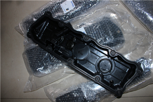
Perkins珀金斯900 3.152柴油发动机37188571摇臂室盖
详细描述
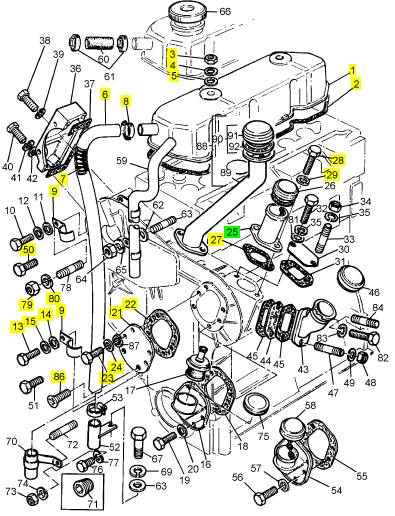
项目 零配件号码 最新件号 描述
1 37188571 1 37188571 摇臂室盖
2 36811115 1 36811115 密合垫 -CYL。 冒口盖
3 0576102 2 0576102 螺帽
4 3314 P004 2 3314 P004 垫圈
4 0920003 2 0920003 垫圈
5 3381 A003 2 3381 A003 垫圈
5 0920302 2 0920302 垫圈
6 33872516 1 33872516 管 -呼吸者
7 31754118 1 31754118 弹簧
8 21825195 1 21825195 夹
9 36561129 2 36561129 夹
13 0748354 1 0748354 螺旋
14 0920002 1 0920002 垫圈
15 0920052 1 0920052 垫圈
21 3623 H005 1 3623 H005 板
22 36862512 1 36862572 密合垫
23 2233103 4 0748352 螺旋
24 2411151 6 2411151 垫圈
25 35784123 1 检查历史 填隙料
27 36837413 1 36837415 密合垫
28 2183204 2 2183204 螺旋
29 0920053 2 0920053 垫圈
50 2233204 1 2233204 螺旋
79 0576002 1 0576002 螺帽
80 0920053 1 0920053 垫圈
86 2227117 6 2227117 螺旋
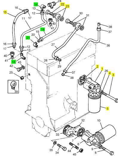
项目 零配件号码 最新件号 描述
1 37764251 1 37764251 滤油器冒口
2 0490514 1 36813161 密合垫 - 滤油器的冒口
3 0096443 2 0096443 螺拴
4 33115129 2 33115129 垫圈
5 2654408 1 2654408 滤油器
14 0201047 2 0201047 连接
15 35352404 1 35352404 油管
18 35568109 1 35568109 油管
21 0201047 1 0201047 连接
22 0095350 1 0095350 螺拴
23 2411118 2 2411118 垫圈
|
Table of Contents |
|
Front Plate - Install ................................................ 57 Crankcase Breather - Remove and Install (Closed Breather) ............................................................. 58 Crankcase Breather - Remove and Install (Open Breather) ............................................................. 59 Valve Mechanism Cover - Remove and Install ..... 60 Valve Mechanism Cover Base - Remove and |
|
Disassembly and Assembly Section |
|
Fuel Priming Pump - Remove and Install .............. 5 Fuel Filter Base - Remove ..................................... 6 Fuel Filter Base - Disassemble ............................... 6 Fuel Filter Base - Assemble .................................... 7 Fuel Filter Base - Install ......................................... 7 Fuel Transfer Pump - Remove ................................ 8 Fuel Transfer Pump - Install .................................... 9 Electronic Unit Injector - Remove ........................... 9 Electronic Unit Injector - Install ............................. 10 Electronic Unit Injector Sleeve - Remove .............. 11 Electronic Unit Injector Sleeve - Install ................. 12 Air Cleaner - Remove and Install .......................... 13 Turbocharger - Remove ........................................ 13 Turbocharger - Install ............................................ 14 Exhaust Manifold - Remove and Install ............... 16 Exhaust Elbow - Remove and Install ................... 17 Inlet Manifold - Remove and Install ..................... 17 Inlet and Exhaust Valve Springs - Remove and |
|
Install ................................................................... 61 Rocker Shaft and Pushrod - Remove ................... 64 Rocker Shaft - Disassemble ................................ 64 Rocker Shaft - Assemble ..................................... 65 Rocker Shaft and Pushrod - Install ....................... 66 Cylinder Head - Remove ...................................... 67 Cylinder Head - Install .......................................... 70 Lifter Group - Remove .......................................... 72 Lifter Group - Disassemble ................................... 73 Lifter Group - Assemble ........................................ 73 Lifter Group - Install .............................................. 74 Camshaft - Remove .............................................. 75 Camshaft - Install .................................................. 76 Camshaft Gear - Remove and Install .................. 78 Camshaft Bearings - Remove ............................... 79 Camshaft Bearings - Install ................................... 79 Engine Oil Pan - Remove and Install ................... 80 Cylinder Liner - Remove ....................................... 83 Cylinder Liner - Install ........................................... 83 Piston Cooling Jets - Remove and Install ............. 84 Pistons and Connecting Rods - Remove .............. 85 Pistons and Connecting Rods - Disassemble ....... 86 Pistons and Connecting Rods - Assemble ........... 87 Pistons and Connecting Rods - Install .................. 88 Crankshaft Main Bearings - Remove (Crankshaft in position) .............................................................. 89 Crankshaft Main Bearings - Install (Crankshaft in position) .............................................................. 90 Crankshaft - Remove ............................................ 92 Crankshaft - Install ................................................ 94 Crankshaft Gear - Remove and Install ................ 96 Bearing Clearance - Check ................................... 97 Atmospheric Pressure Sensor - Remove and |
|
Install ................................................................... 19 Inlet and Exhaust Valves - Remove and Install .... 21 Inlet and Exhaust Valve Guides - Remove and |
|
Install ................................................................... 23 Engine Oil Filter Base - Remove .......................... 24 Engine Oil Filter Base - Disassemble ................... 25 Engine Oil Filter Base - Assemble ........................ 27 Engine Oil Filter Base - Install .............................. 28 Engine Oil Cooler - Remove ................................. 29 Engine Oil Cooler - Install ..................................... 30 Engine Oil Pump - Remove .................................. 32 Engine Oil Pump - Disassemble ........................... 33 Engine Oil Pump - Assemble ................................ 33 Engine Oil Pump - Install ...................................... 34 Water Pump - Remove ......................................... 35 Water Pump - Install ............................................. 37 Water Temperature Regulator Housing - Remove and Install .................................................................. 38 Engine Support (Front) - Remove and Install ....... 40 Flywheel - Remove ............................................... 41 Flywheel - Install ................................................... 41 Crankshaft Rear Seal - Remove ........................... 43 Crankshaft Rear Seal - Install ............................... 43 Crankshaft Wear Sleeve (Rear) - Remove and Install ................................................................... 44 Flywheel Housing - Remove and Install .............. 45 Vibration Damper and Pulley - Remove and Install ............................................................................. 47 Crankshaft Front Seal - Remove .......................... 48 Crankshaft Front Seal - Install .............................. 49 Crankshaft Wear Sleeve (Front) - Remove and Install ................................................................... 50 Front Cover - Remove .......................................... 51 Front Cover - Install .............................................. 51 Gear Group (Front) - Remove .............................. 52 Gear Group (Front) - Install .................................. 54 Housing (Front) - Remove .................................... 55 Housing (Front) - Install ........................................ 55 Front Plate - Remove ............................................ 56 |
|
Install ................................................................... 98 Camshaft Position Sensor - Remove and Install .. 99 Crankshaft Position Sensor - Remove and Install ................................................................. 100 Coolant Temperature Sensor - Remove and |
|
Install ................................................................. 101 Engine Oil Pressure Sensor - Remove and Install ........................................................................... 102 Fuel Temperature Sensor - Remove and Install .. 103 Inlet Manifold Temperature Sensor - Remove and Install ................................................................. 104 Inlet Manifold Pressure Sensor - Remove and Install ................................................................. 105 Belt Tightener - Remove ..................................... 105 Belt Tightener - Install ......................................... 106 Fan - Remove and Install ................................... 107 Fan Drive - Remove ........................................... 107 Fan Drive - Disassemble ................................... 108 Fan Drive - Assemble ......................................... 110 Fan Drive - Install ................................................. 112 Pump Drive - Remove (Transfer pump) ............... 113 Pump Drive - Disassemble (Transfer pump) ........ 113 Pump Drive - Assemble (Transfer pump) ............ 113 |
|
This document has been printed from SPI². Not for Resale |
![]()
|
4 |
|
KENR6906 |
|
Table of Contents |
|
Pump Drive - Install (Transfer pump) ................... 114 Electronic Control Module - Remove and Install .. 114 Alternator - Remove and Install .......................... 116 Electric Starting Motor - Remove and Install ...... 117 |
|
Index Section |
|
Index .................................................................... 118 |
|
This document has been printed from SPI². Not for Resale |
![]()
|
KENR6906 |
|
5 Disassembly and Assembly Section |
|
Disassembly and Assembly Section |
|
Installation Procedure |
|
NOTICE |
|
Keep all parts clean from contaminants. |
|
i02736695 Fuel Priming Pump - Remove and Install |
|
Contaminants may cause rapid wear and shortened component life. |
|
Removal Procedure |
|
NOTICE |
|
Care must be taken to ensure that fluids are contained during performance of inspection, maintenance, test- ing, adjusting and repair of the product. Be prepared to collect the fluid with suitable containers before open- ing any compartment or disassembling any compo- nent containing fluids. |
|
Dispose of all fluids according to local regulations and mandates. |
|
NOTICE Keep all parts clean from contaminants. |
|
g01380207 |
|
Contaminants may cause rapid wear and shortened component life. |
|
Illustration 2 |
|
Typical example |
|
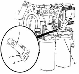
1. Position a new joint (3) on fuel filter base (4). Note: Ensure correct orientation of the joint. |
|
1. Turn the fuel supply to the “OFF” position. |
|
2. Position fuel priming pump (1) on fuel filter base (4) and install bolts (2). Tighten the 1/4" bolt to a torque of 12 N·m (105 lb in). Tighten the 5/16" bolt to a torque of 25 N·m (221 lb in). |
|
3. Turn the fuel supply to the “ON” position. |
|
4. Remove the air from the fuel system. Refer to Operation and Maintenance Manual, “Fuel System - Prime”. |
|
g01380207 |
|
Illustration 1 |
|
Typical example |
|
2. Remove bolts (2). Remove fuel priming pump (1) from fuel filter base (4). |
|
3. Remove joint (3). |
|
This document has been printed from SPI². Not for Resale |
![]()
![]()
![]()
![]()
![]()
![]()
![]()
![]()
![]()

|
6 Disassembly and Assembly Section |
|
KENR6906 |
|
i02754755 |
|
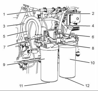
5. Disconnect hose assembly (2). Disconnect hose assembly (4). Disconnect hose assemblies (3) and (5). Cap the hose assemblies. |
|
Fuel Filter Base - Remove |
|
6. Remove fuel filters (9) and (10). Remove the O-ring seals and the fuel filter elements from the fuel filters. Refer to Operation and Maintenance Manual, “Fuel System Primary Filter - Replace” and refer to Operation and Maintenance Manual, “Fuel System Secondary Filter - Replace” for more information. |
|
Removal Procedure |
|
NOTICE |
|
Care must be taken to ensure that fluids are contained during performance of inspection, maintenance, test- ing, adjusting and repair of the product. Be prepared to collect the fluid with suitable containers before open- ing any compartment or disassembling any compo- nent containing fluids. |
|
7. Remove bolts (6). Remove fuel filter base (8). |
|
i02754756 |
|
Fuel Filter Base - Disassemble |
|
Dispose of all fluids according to local regulations and mandates. |
|
NOTICE Keep all parts clean from contaminants. |
|
Disassembly Procedure |
|
Start By: |
|
Contaminants may cause rapid wear and shortened component life. |
|
a. Remove the fuel filter base. Refer to Disassembly |
|
and Assembly, “Fuel Filter Base - Remove”. |
|
1. Turn the fuel supply to the “OFF” position. |
|
NOTICE Keep all parts clean from contaminants. |
|
2. Place a suitable container below the fuel filter base in order to drain the fuel. |
|
Contaminants may cause rapid wear and shortened component life. |
|
g01380210 |
|
Illustration 4 |
|
Typical example |
|
g01380208 |
|
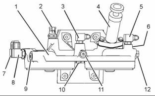
1. Remove fuel priming pump (4) from fuel filter base (1). Refer to Disassembly and Assembly, “Fuel Priming Pump - Remove and Install” for the correct procedure. |
|
Illustration 3 |
|
Typical example |
|
3. Remove plugs (11) and (12). Allow the fuel to |
|
drain. |
|
2. Remove fuel temperature sensor (2) from fuel filter base (1). Refer to Disassembly and Assembly, “Fuel Temperature Sensor - Remove and Install” for the correct procedure. |
|
4. Slide the locking tab into the unlocked position and disconnect harness assembly (1) from fuel temperature sensor (7). |
|
This document has been printed from SPI². Not for Resale |
![]()
![]()
![]()
![]()
![]()
![]()
![]()
![]()
![]()
|
KENR6906 |
|
7 Disassembly and Assembly Section |
|
3. Remove fuel bypass valve (6) (not shown) from fuel filter base (1). Remove the O-ring seals from the fuel bypass valve. |
|
Note: Ensure correct orientation of the connections. |
|
4. Install new O-ring seals to fuel bypass valve (6) (not shown). Install the fuel bypass valve to fuel filter base (1). Tighten the fuel bypass valve to a torque of 35 N·m (26 lb ft). |
|
4. Remove fuel check valve (10) from fuel filter base (1). Remove the O-ring seals from the fuel check valve. |
|
5. Install new O-ring seals to fuel check valve (10). Install the fuel check valve to fuel filter base (1). Tighten the fuel check valve to a torque of 35 N·m (26 lb ft). |
|
5. Remove connections (3), (5), (7) and (8) from fuel filter base (1). Remove the O-ring seals from the connections. |
|
6. Remove plugs (9), (11) and (12) from fuel filter base (1). Remove the O-ring seals from the plugs. |
|
6. Install fuel temperature sensor (2) to fuel filter base (1). Refer to Disassembly and Assembly, “Fuel Temperature Sensor - Remove and Install” for the correct procedure. |
|
i02754757 |
|
Fuel Filter Base - Assemble |
|
7. Install fuel priming pump (4) to fuel filter base (1). Refer to Disassembly and Assembly, “Fuel Priming Pump - Remove and Install” for the correct procedure. |
|
Assembly Procedure |
|
End By: |
|
a. Install the fuel filter base. Refer to Disassembly and Assembly, “Fuel Filter Base - Install”. |
|
NOTICE Keep all parts clean from contaminants. |
|
Contaminants may cause rapid wear and shortened component life. |
|
i02754758 |
|
Fuel Filter Base - Install |
|
1. Ensure that the fuel filter base is clean and free from damage. If necessary, replace the fuel filter base. |
|
Installation Procedure |
|
Table 1 |
|
Required Tools Part |
|
Tool |
|
Number |
|
Part Description |
|
Qty |
|
POWERPART Special Lubricant |
|
A |
|
CV60889 |
|
1 |
|
NOTICE Keep all parts clean from contaminants. |
|
Contaminants may cause rapid wear and shortened component life. |
|
g01380210 |
|
Illustration 5 |
|
Typical example |
|
2. Install new O-ring seals to plugs (9), (11) and (12). Install the plugs to fuel filter base (1). Tighten plug (9) to a torque of 41 N·m (30 lb ft). Tighten plugs (11) and (12) to a torque of 15 N·m (11 lb ft). |
|
3. Install new O-ring seals to connections (3), (5), (7) and (8). Install the connections to fuel filter base (1). Tighten connections (3), (5) and (7) to a torque of 15 N·m (11 lb ft). Tighten connection (8) to a torque of 41 N·m (30 lb ft). |
|
This document has been printed from SPI². Not for Resale |