 English
 Espaol
 Franais
 阿拉伯
阿拉伯 中文
中文 Deutsch
 Italiano
 Português
 日本
日本 韩国
韩国 български
 hrvatski
 esky
esky Dansk
Dansk Nederlands
 suomi
suomi Ελληνικ
 印度
印度 norsk
norsk Polski
 Roman
Roman русский
 Svenska
Perkins珀金斯900 3.152柴油发动机37172493油底壳供应商,Perkins珀金斯900 3.152柴油发动机37172493油底壳技术价格规格咨询服务,Perkins珀金斯900 3.152柴油发动机37172493油底壳零配件供应,Perkins珀金斯900 3.152柴油发动机37172493油底壳售后服务中心,Perkins珀金斯900 3.152柴油发动机37172493油底壳,Perkins珀金斯900 3.152柴油发动机37172493油底壳详细的技术参数,

产品中心
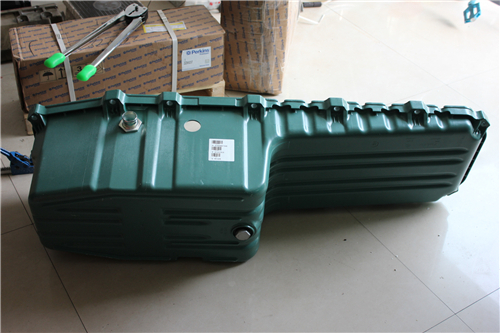
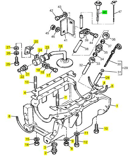
Perkins珀金斯900 3.152柴油发动机37172493油底壳
详细描述
项目 零配件号码 最新件号 描述
1 37172493 1 37172493 油底壳
2 32186405 1 32186405 栓塞
3 2415715 1 2415715 密封 - O 的圈
4 41424233 1 21826370 密合垫 -油底壳
5 3688 V002 1 检查历史 密封 -油底壳
6 3688 V003 1 检查历史 密封 -油底壳
7 0826265 2 0826265 图钉
8 0576002 2 0576002 螺帽
9 0920053 2 0920053 垫圈
10 0096245 2 0096245 螺拴
11 0920053 13 0920053 垫圈
12 0746211 11 0746211 螺拴
13 0826285 1 0826285 图钉
14 0576002 1 0576002 螺帽
15 0920053 1 0920053 垫圈
16 35137623 1 35137623 油管
17 0746052 1 0746052 螺拴
18 0920002 1 0920002 垫圈
19 0920052 1 0920052 垫圈
20 38311124 1 38311124 托架
21 33532121 1 33532121 螺帽
22 0560244 1 0560244 橄榄
23 33817308 1 33817308 衬套
24 36631118 1 36631118 夹
25 0746053 1 0746053 螺拴
26 0920052 1 0920052 垫圈
27 0920002 1 0920002 垫圈
28 33242412 1 33242412 管
40 3178 C068 1 3178 C068 量油计
|
Disassembly and Assembly Section |
|
KENR6906 |
|
i02754760 |
|
Fuel Transfer Pump - Remove |
|
Removal Procedure |
|
NOTICE |
|
Care must be taken to ensure that fluids are contained during performance of inspection, maintenance, test- ing, adjusting and repair of the product. Be prepared to collect the fluid with suitable containers before open- ing any compartment or disassembling any compo- nent containing fluids. |
|
Dispose of all fluids according to local regulations and mandates. |
|
NOTICE |
|
g01380208 |
|
Keep all parts clean from contaminants. |
|
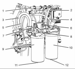
Illustration 6 |
|
Typical example |
|
Contaminants may cause rapid wear and shortened component life. |
|
1. Position fuel filter base (8) onto the mounting bracket and install bolts (6). Tighten the bolts to a torque of 55 N·m (41 lb ft). |
|
1. Turn the fuel supply to the “OFF” position. |
|
2. Install new O-ring seals and new fuel filter elements to fuel filters (9) and (10). Apply Tooling (A) to the threads of the fuel filters. Install the fuel filters to fuel filter base (8). Tighten the fuel filters. |
|
2. Place a suitable container below the fuel transfer pump in order to catch any fuel that might be spilled. |
|
Refer to Operation and Maintenance Manual, “Fuel Filter Primary Filter - Replace” and refer to Operation and Maintenance Manual, “Fuel Filter Secondary Filter - Replace” for more information. |
|
3. Install new O-ring seals to plugs (11) and (12). Install the plugs to fuel filters (9) and (10). |
|
4. Connect hose assemblies (2), (3), (4) and (5). |
|
5. Connect harness assembly (1) to fuel temperature sensor (7). Slide the locking tab into the locked position. |
|
6. Turn the fuel supply to the “ON” position. |
|
7. Remove the air from the fuel system. Refer to Operation and Maintenance Manual, “Fuel System - Prime”. |
|
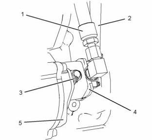
g01380887 |
|
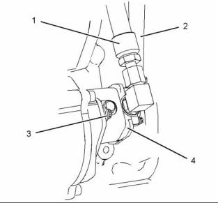
Illustration 7 |
|
Typical example |
|
3. Disconnect hose assemblies (1) and (2) from fuel transfer pump (4). Cap the hose assemblies. |
|
4. Remove bolts (3) and remove fuel transfer pump (4). |
|
This document has been printed from SPI². Not for Resale |
![]()
![]()
![]()
![]()
![]()
![]()
![]()
|
KENR6906 |
|
9 Disassembly and Assembly Section |
|
5. Remove the O-ring seal from fuel transfer pump (4). |
|
7. Remove the air from the fuel system. Refer to Systems Operation and Maintenance Manual, “Fuel System - Prime”. |
|
i02754761 |
|
Fuel Transfer Pump - Install |
|
i02754762 Electronic Unit Injector - Remove |
|
Installation Procedure |
|
NOTICE Keep all parts clean from contaminants. |
|
Removal Procedure |
|
Table 2 |
|
Contaminants may cause rapid wear and shortened component life. |
|
Required Tools |
|
Tool |
|
Part Number |
|
Part Description |
|
Qty |
|
1. Ensure that the fuel transfer pump is clean and |
|
A |
|
27610288 |
|
Pry Bar |
|
1 |
|
free from damage. |
|
Start By: |
|
a. Remove the rocker shafts. Refer to Disassembly and Assembly, “Rocker Shaft and Pushrod - Remove”. |
|
NOTICE Keep all parts clean from contaminants. |
|
Contaminants may cause rapid wear and shortened component life. |
|
1. Turn the fuel supply to the OFF position. |
|
g01416997 |
|
Illustration 8 |
|
Typical example |
|
2. Lubricate a new O-ring seal with clean engine oil. Install the O-ring seal to fuel transfer pump (4). |
|
3. Position fuel transfer pump (4) on pump drive (5). |
|
g01411598 |
|
Illustration 9 |
|
Note: Ensure that the splines on the shaft of the fuel transfer pump are correctly engaged into the pump drive. |
|
2. Disconnect hoses (1) and (2) from the fuel filter base in order to drain fuel from the cylinder head. |
|
4. Install bolts (3). Tighten the bolts to a torque of 55 N·m (41 lb ft). |
|
5. Remove the caps from the hose assemblies. Connect hose assemblies (1) and (2) to fuel transfer pump (4). |
|
6. Turn the fuel supply to the “ON” position. |
|
This document has been printed from SPI². Not for Resale |
![]()
![]()
![]()
![]()
![]()
![]()
![]()
![]()
|
10 |
|
KENR6906 |
|
Disassembly and Assembly Section |
|
i02754763 |
|
Electronic Unit Injector - Install |
|
Installation Procedure |
|
Table 3 |
|
Required Tools |
|
Tool B |
|
Part Number GE50023 GE50024 GE50028 GE50046 |
|
Part Description Tapered Brush |
|
Qty 1 |
|
C |
|
Small Bore Brush Vacuum Pump |
|
1 |
|
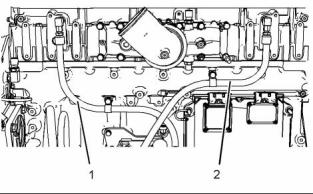
g01380214 |
|
Illustration 10 |
|
1 |
|
3. Disconnect harness assembly (3) from electronic |
|
Fluid Sampling Bottle |
|
1 |
|
unit injector (4). |
|
D E |
|
Tube 7.9 mm (0.31 inch) OD |
|
GE50030 |
|
1 1 |
|
4. Remove bolt (5). |
|
5. Place an identification mark on electronic unit injector (4) for installation purposes. Each electronic unit injector must be reinstalled in the original location in the cylinder head. |
|
27610296 |
|
Torque Wrench |
|
NOTICE |
|
Keep all parts clean from contaminants. |
|
6. Use Tooling (A) to pry beneath clamp (6) and free electronic unit injector (4). |
|
Contaminants may cause rapid wear and shortened component life. |
|
7. Remove electronic unit injector (4) and clamp (6) |
|
from the cylinder head. |
|
1. Use Tooling (B) and (C) to clean the carbon deposit from the inside of the electronic unit injector sleeve. |
|
2. Use Tooling (D) to remove the fuel and oil from the cylinder. Evacuate as much fuel and oil as possible from the cylinder before installing the electronic unit injector. Several evacuations may be necessary. |
|
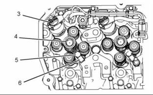
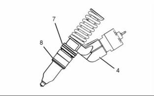
g01380213 |
|
Illustration 11 |
|
8. Remove O-ring seals (7) and (8) from electronic unit injector (4). |
|
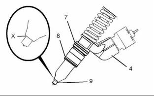
g01380273 |
|
Illustration 12 |
|
3. Ensure that seat area (X) on electronic unit injector (4) is clean and free carbon. |
|
This document has been printed from SPI². Not for Resale |
![]()
![]()
![]()

![]()
![]()
![]()
|
KENR6906 |
|
11 Disassembly and Assembly Section |
|
4. Install new O-ring seals (7) and (8) to electronic unit injector (4). Lubricate the O-ring seals with clean engine oil. |
|
11. Remove the air from the fuel system. Refer to Operation and Maintenance Manual, “Fuel System - Prime”. |
|
5. Install a new O-ring seal (9) to electronic unit |
|
End By: |
|
injector (4). |
|
a. Install the rocker shafts. Refer to Disassembly and |
|
Note: O-ring seal (9) should be installed dry. |
|
Assembly, “Rocker Shaft and Pushrod - Install”. |
|
NOTICE |
|
i02754765 Electronic Unit Injector Sleeve - Remove |
|
If a replacement electronic unit injector is installed, the calibration code must be programmed into the elec- tronic control module. Refer to Troubleshooting Guide, “Injector Trim File” for more information. |
|
Removal Procedure |
|
Table 4 |
|
Required Tools |
|
Tool |
|
Part Number |
|
Part Description |
|
Qty |
|
A |
|
GE50021 |
|
Injector Sleeve Tool |
|
1 |
|
NOTICE Keep all parts clean from contaminants. |
|
Contaminants may cause rapid wear and shortened component life. |
|
g01380214 |
|
Illustration 13 |
|
6. Install clamp (6) to electronic unit injector (4). Install electronic unit injector (4) into the original location in the cylinder head. |
|
1. Drain the coolant from the cooling system into a suitable container for storage or for disposal. Refer to Operation and Maintenance Manual, “Cooling System Coolant - Change”. |
|
7. Install bolt (5). Tighten the bolt to a torque of 55 N·m (41 lb ft). |
|
2. Remove the electronic unit injectors. Refer to, Disassembly and Assembly, “Electronic Unit Injector - Remove”. |
|
8. Connect harness assembly (3) to electronic unit injector (4). Use Tooling (E) to tighten the nuts to a torque of 2.5 N·m (22 lb in). |
|
g01391954 |
|
Illustration 15 |
|
g01411598 |
|
Illustration 14 |
|
3. Install Tooling (A) into electronic unit injector sleeve (1). |
|
9. Connect hoses (1) and (2) to the fuel filter base. 10. Turn the fuel supply to the “ON” position. |