 English
 Espaol
 Franais
 阿拉伯
阿拉伯 中文
中文 Deutsch
 Italiano
 Português
 日本
日本 韩国
韩国 български
 hrvatski
 esky
esky Dansk
Dansk Nederlands
 suomi
suomi Ελληνικ
 印度
印度 norsk
norsk Polski
 Roman
Roman русский
 Svenska
Perkins珀金斯900 3.152柴油发动机4115 R807摇臂总成供应商,Perkins珀金斯900 3.152柴油发动机4115 R807摇臂总成技术价格规格咨询服务,Perkins珀金斯900 3.152柴油发动机4115 R807摇臂总成零配件供应,Perkins珀金斯900 3.152柴油发动机4115 R807摇臂总成售后服务中心,Perkins珀金斯900 3.152柴油发动机4115 R807摇臂总成,Perkins珀金斯900 3.152柴油发动机4115 R807摇臂总成详细的技术参数,

产品中心
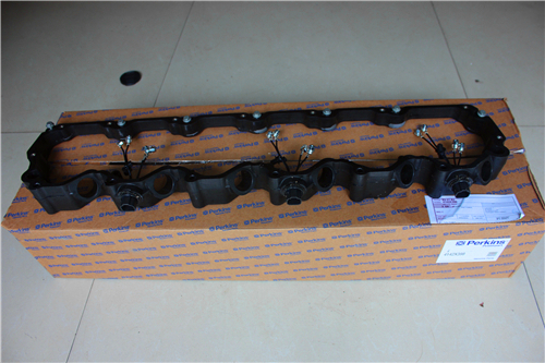
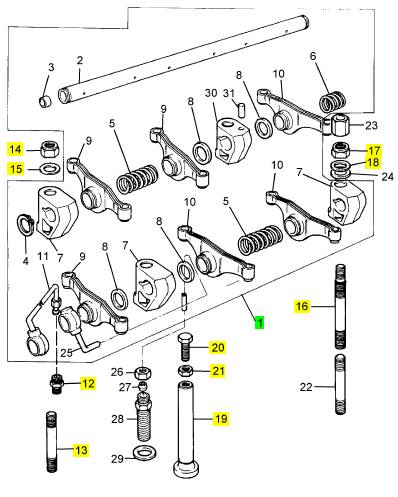
Perkins珀金斯900 3.152柴油发动机4115 R807摇臂总成
详细描述
项目 零配件号码 最新件号 描述
1 4115 R807 1 4115 R807 摇臂总成
12 0206002 1 0206002 管套节
13 2214209 2 2214209 图钉
14 2211283 2 2211283 螺帽
15 0920004 2 0920004 垫圈
16 32754435 2 32754435 图钉
17 2211283 2 2211283 螺帽
18 0920004 2 0920004 垫圈
19 0860012 6 0860012 挺杆
20 32151116 6 32151116 螺旋
21 0576052 6 0576052 螺帽
项目 零配件号码 最新件号 描述
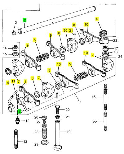
2 ZZ90047 1 ZZ90047 摇臂轴
4 0170033 2 0170033 CIRCLIP
5 0780005 2 0780005 摇臂轴弹簧
6 0780175 1 0780175 摇臂轴弹簧
7 3818 X121 4 3818 X121 托架
7 0101138 3 3818 X121 托架
8 0330505 5 0330505 间隔器
9 3737 A091 3 3737 A091 摇臂
10 3737 A101 3 3737 A101 摇臂
11 35568352 1 35568352 油管
30 37521212 1 3818 X121 托架
31 2112 A066 1 2112 A066 销
项目 零配件号码 最新件号 描述
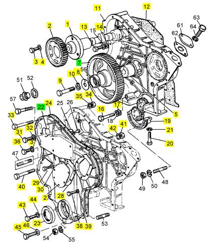
1 31415261 1 3141 A022 凸轮轴
2 0410241 1 3116 K111 凸轮轴传动机构
3 0746214 3 0746214 螺旋
4 0920053 3 0920053 垫圈
5 0995447 1 0995447 轮毂
6 0350005 1 0350005 合钉
7 31164362 1 4111 A015 惰轮传动机构
8 3241 H013 1 3241 H013 板
9 0095199 1 0095199 螺拴
10 0920883 1 0920883 垫圈
11 37161481 1 37161481 正时齿轮箱
12 36814119 1 36814161 密合垫 - 正时齿轮箱
13 0746355 12 0746355 螺旋
14 0920053 12 0920053 垫圈
16 0096234 2 0096234 螺拴
17 0920053 2 0920053 垫圈
19 37354312 1 37354312 盖
20 0746259 2 0746259 螺旋
21 0920053 2 0920053 垫圈
22 ZZ90039 1 ZZ90039 护封总成
23 2415344 1 2415344 密封 -前面端油
24 36813136 1 3681 P026 密合垫 - 时间安排的盖
27 1 盖
28 1 接合
29 6 螺旋
30 6 垫圈
31 0748414 2 0748414 固定螺钉
32 0920053 2 0920053 垫圈
33 0096213 1 0096213 螺拴
34 0576002 1 0576002 螺帽
35 0920053 1 0920053 垫圈
36 0748412 1 0748412 螺旋
37 0920106 1 0920106 垫圈
38 0748354 8 0748354 螺旋
39 0920052 8 0920052 垫圈
40 0748510 2 0748510 螺拴
41 2238153 2 2238153 螺帽
42 0920054 2 0920054 垫圈
43 2233207 3 2233207 螺旋
44 0920053 3 0920053 垫圈
45 2233207 1 2233207 螺旋
46 2411152 1 2411152 垫圈
|
8. Follow Steps 8.a through 8.c in order to install the |
|
Note: Remove the manifolds as one assembly. |
|
tube assembly for the oil feed to the turbocharger. |
|
3. Remove the exhaust manifold gaskets. |
|
a. Place a new joint (3) and tube assembly (2) in position on turbocharger (4). |
|
4. Remove exhaust manifolds (4) and (6) from |
|
exhaust manifold (5). |
|
b. Install bolts (1). Tighten the bolts to a torque of |
|
28 N·m (21 lb ft). |
|
5. If necessary, remove the taperlock studs from the |
|
cylinder head. |
|
c. Connect tube assembly (2) to the engine oil filter base. |
|
Installation Procedure |
|
9. Connect the air hoses to the turbocharger inlet and the turbocharger outlet. |
|
Table 7 |
|
Required Tools |
|
If a new turbocharger was installed, tighten the V-band clamp for the exhaust housing to 13.5 N·m (120 lb in). Tighten the V-band clamp for the compressor housing to 18 N·m (160 lb in). |
|
Tool |
|
Part Number |
|
Part Description |
|
Qty |
|
A |
|
CV60889 |
|
Anti-Seize Compound |
|
1 |
|
NOTICE Keep all parts clean from contaminants. |
|
End By: |
|
a. Install the exhaust elbow. Refer to Disassembly and Assembly, “Exhaust Elbow - Remove and Install” |
|
Contaminants may cause rapid wear and shortened component life. |
|
1. If necessary, install the taperlock studs to the cylinder head. Tighten the taperlock studs to a torque of 35 N·m (26 lb ft). |
|
i02754773 Exhaust Manifold - Remove and Install |
|
Removal Procedure |
|
Start By: |
|
a. Remove the turbocharger. Refer to Disassembly and Assembly, “Turbocharger - Remove”. |
|
g01380890 |
|
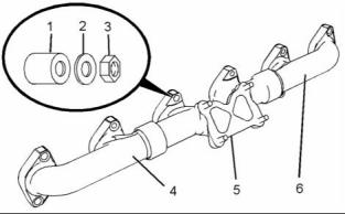
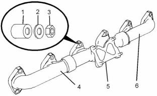
Illustration 26 |
|
2. Assemble exhaust manifolds (4), (5) and (6). |
|
3. Position the exhaust manifold gaskets onto the taperlock studs. |
|
4. Install the assembly of the exhaust manifolds to the cylinder head. |
|
Note: Ensure that the holes in exhaust manifolds are |
|
centralized with the taperlock studs. |
|
g01380890 |
|
Illustration 25 |
|
5. Apply Tooling (A) to the threads of the taperlock studs. Install spacers (1), washers (2) and nuts (3). |
|
1. Remove nuts (3), washers (2) and spacers (1). 2. Remove exhaust manifolds (4), (5) and (6). |
|
This document has been printed from SPI². Not for Resale |
![]()
![]()
![]()
![]()
![]()
![]()
|
KENR6906 |
|
17 Disassembly and Assembly Section |
|
Installation Procedures |
|
NOTICE Keep all parts clean from contaminants. |
|
Contaminants may cause rapid wear and shortened component life. |
|
g01380891 |
|
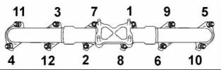
Illustration 27 |
|
1. Thoroughly clean the exhaust elbow and the outlet of the turbocharger. Inspect the components for wear or damage. Replace any components that are worn or damaged. |
|
6. Tighten the nuts to a torque of 55 N·m (41 lb ft) in a numerical sequence that is shown in Illustration 27. |
|
End By: |
|
a. Install the turbocharger. Refer to Disassembly and Assembly, “Turbocharger - Install”. |
|
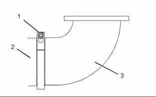
i02754774 Exhaust Elbow - Remove and Install |
|
Removal Procedure |
|
g01382827 |
|
Illustration 29 |
|
NOTICE Keep all parts clean from contaminants. |
|
2. Position clamp (1) and install exhaust elbow (3) to turbocharger (2). Ensure correct orientation of the clamp. |
|
Contaminants may cause rapid wear and shortened component life. |
|
3. Tighten clamp (1) to a torque of 14 N·m (10 lb ft). |
|
i02763449 Inlet Manifold - Remove and Install |
|
Removal Procedure |
|
NOTICE Keep all parts clean from contaminants. |
|
Contaminants may cause rapid wear and shortened component life. |
|
g01382827 |
|
Illustration 28 |
|
1. Loosen clamp (1). |
|
2. Remove exhaust elbow (3) and clamp (1) from turbocharger (2). |
|
This document has been printed from SPI². Not for Resale |
![]()
![]()
![]()
![]()
![]()

![]()
![]()
![]()
![]()
![]()
|
18 |
|
KENR6906 |
|
Disassembly and Assembly Section |
|
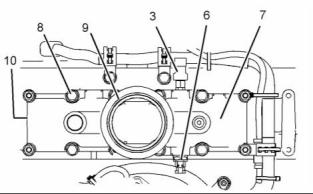
6. Remove fasteners (8). Note the position of the |
|
brackets that are retained by the fasteners. 7. Remove inlet manifold (7) from the cylinder head. 8. Remove gasket (10) (not shown). |
|
9. If necessary, remove inlet manifold pressure sensor (3) and remove inlet manifold temperature sensor (6) from inlet manifold (7). Refer to Disassembly and Assembly, “Inlet Manifold Pressure Sensor - Remove and Install” and Disassembly and Assembly, “Inlet Manifold Temperature Sensor - Remove and Install” for more information. |
|
Installation Procedure |
|
NOTICE Keep all parts clean from contaminants. |
|
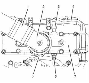
g01383308 |
|
Illustration 30 |
|
Contaminants may cause rapid wear and shortened component life. |
|
Typical example |
|
1. Loosen the hose clamps and disconnect air hose (1) from connection (2). |
|
1. Ensure that all mating surfaces are clean and free from debris. |
|
2. Slide the locking tab into the unlocked position and disconnect harness assembly (4) from inlet manifold pressure sensor (3). |
|
3. Slide the locking tab into the unlocked position and disconnect harness assembly (4) from inlet manifold temperature sensor (6). |
|
4. Loosen clamp (5) and remove connection (2) from inlet manifold (7). |
|
Note: Make a temporary mark in order to show the orientation of the connection. |
|
g01384161 |
|
Illustration 32 |
|
Typical example |
|
2. Place a new gasket (10) (not shown) in position on inlet manifold (7). |
|
3. Position inlet manifold (7) on the cylinder head. |
|
4. Install fasteners (8). Ensure that the brackets that are retained by the fasteners are installed in the correct positions. |
|
5. Tighten fasteners (8) to a torque of 55 N·m (41 lb ft). |
|
g01384161 |
|
Illustration 31 |
|
Typical example |
|
6. Install a new O-ring seal (9) to inlet manifold (7). |
|
5. Remove O-ring seal (9) from inlet manifold (7). |
|
This document has been printed from SPI². Not for Resale |
![]()
![]()
![]()
![]()
![]()
![]()

|
KENR6906 |
|
19 Disassembly and Assembly Section |
|
i02754775 |
|
Inlet and Exhaust Valve Springs - Remove and Install |
|
Removal Procedure |
|
Table 8 |
|
Required Tools |
|
Tool A |
|
Part Number CH11148 |
|
Part Description Engine Turning Tool |
|
Qty 1 |
|
B |
|
CVT0003 |
|
Valve Spring Compressor |
|
1 |
|
Start By: |
|
a. Remove the electronic unit injectors. Refer to Disassembly and Assembly, “Electronic Unit Injector - Remove”. |
|
g01383308 |
|
Illustration 33 |
|
Typical example |
|
7. Install connection (2) and clamp (5) to inlet manifold (7). Tighten the clamp to a torque of 14 N·m (10 lb ft). |
|
NOTICE Keep all parts clean from contaminants. |
|
Contaminants may cause rapid wear and shortened component life. |
|
Note: Ensure correct orientation of the connection. |
|
8. If necessary, install inlet manifold pressure sensor (3) and install inlet manifold temperature sensor (6) to inlet manifold (7). Refer to Disassembly and Assembly, “Inlet Manifold Pressure Sensor - Remove and Install” and Disassembly and Assembly, “Inlet Manifold Temperature Sensor - Remove and Install” for more information. |
|
Note: The following procedure should be adopted in order to remove the valve springs when the cylinder head is installed to the engine. Refer to Disassembly and Assembly, “Inlet and Exhaust Valves - Remove and Install” for the procedure to remove the valve springs from a cylinder head that has been removed from the engine. |
|
9. Connect harness assembly (4) to inlet manifold pressure sensor (3) and slide the locking tab into the locked position. |
|
1. Use Tooling (A) to position the appropriate piston at the top center position before the valve spring is removed. |
|
10. Connect harness assembly (4) to inlet manifold temperature sensor (6) and slide the locking tab into the locked position. |
|
Note: Failure to ensure that the piston is at the top center position may allow the valve to drop into the cylinder bore. |
|
11. Connect air hose (1) to connection (2) and tighten the hose clamps securely. |
|
NOTICE Do not turn the crankshaft while the valve springs are removed. |
|
Note: Valve springs must be replaced in pairs for the inlet valves or the exhaust valves of each cylinder. If all valve springs require replacement the procedure can be carried out on two cylinders at the same time. The procedure can be carried out on the following pairs of cylinders. 1 with 6, 2 with 5, and 3 with 4. Ensure that all of the valve springs are installed before changing from one pair of cylinders to another pair of cylinders. |
|
This document has been printed from SPI². Not for Resale |
![]()
![]()
![]()
![]()
![]()
![]()
|
20 |
|
KENR6906 |
|
Disassembly and Assembly Section |
|
8. Remove spring seats (7) from the valve guides. |
|
g01411612 |
|
Illustration 35 |
|
9. If necessary, remove valve stem seals (8). |
|
Installation Procedure |
|
g01380893 |
|
Illustration 34 |
|
Table 9 |
|
Required Tools |
|
Tool |
|
Part Number |
|
Part Description |
|
Qty |
|
Personal injury can result from being struck by parts propelled by a released spring force. |
|
B |
|
CVT0003 |
|
Valve Spring Compressor |
|
1 |
|
Make sure to wear all necessary protective equip- ment. |
|
NOTICE Keep all parts clean from contaminants. |
|
Follow the recommended procedure and use all recommended tooling to release the spring force. |
|
Contaminants may cause rapid wear and shortened component life. |
|
NOTICE |
|
1. Inspect the valve springs for damage and for the correct length. Refer to Specifications, “Cylinder Head Valves ”. |
|
Plug the apertures for the push rods in the cylinder head in order to prevent the entry of loose parts into the engine. |
|
2. Lubricate the valve stems with clean engine oil. |
|
2. Position electronic unit injector clamp (1) on Tooling (B). Install Tooling (B) into the electronic unit injector sleeve. Tighten the bolt on the electronic unit injector clamp in order to secure Tooling (B). |
|
3. Tighten the nut on Tooling (B) until valve keepers (3) are loose on valves (2). |
|
4. Remove valve keepers (3). |
|
5. Loosen the nut in order to release the pressure on Tooling (B). Remove electronic unit injector clamp (1) and Tooling (B) from the electronic unit injector sleeve. |
|
g01411612 |
|
Illustration 36 |
|
6. Remove valve rotators (4). |
|
3. If necessary, install new valve stem seals (8). |
|
7. Remove outer valve springs (5) and inner valve springs (6). |
|
This document has been printed from SPI². Not for Resale |