 English
 Espaol
 Franais
 阿拉伯
阿拉伯 中文
中文 Deutsch
 Italiano
 Português
 日本
日本 韩国
韩国 български
 hrvatski
 esky
esky Dansk
Dansk Nederlands
 suomi
suomi Ελληνικ
 印度
印度 norsk
norsk Polski
 Roman
Roman русский
 Svenska
Perkins珀金斯900 3.152柴油发动机U5MK0059缸套供应商,Perkins珀金斯900 3.152柴油发动机U5MK0059缸套技术价格规格咨询服务,Perkins珀金斯900 3.152柴油发动机U5MK0059缸套零配件供应,Perkins珀金斯900 3.152柴油发动机U5MK0059缸套售后服务中心,Perkins珀金斯900 3.152柴油发动机U5MK0059缸套,Perkins珀金斯900 3.152柴油发动机U5MK0059缸套详细的技术参数,

产品中心
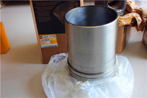
Perkins珀金斯900 3.152柴油发动机U5MK0059缸套
详细描述
项目 零配件号码 最新件号 描述
1 U5MK0059 1 U5MK0059 缸套
1 U5MK0117 1 检查历史 缸套
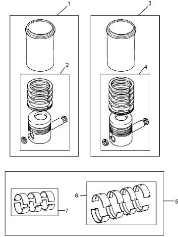
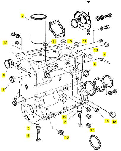
项目 零配件号码 最新件号 描述
2 31358323 3 31358323 缸套
(2) 31358345 3 31358345 缸套
(2) 31358357 3 31358357 缸套
(2) 31358384 3 31358384 缸套
3 33137409 8 33137409 套管
4 32181441 6 32181441 螺旋
5 32181442 2 32181442 螺旋
6 31134128 1 31134128 凸轮轴衬套
7 2485 A304 1 2485 A304 栓塞
8 0650710 5 0650710 栓塞
9 0650710 1 0650710 栓塞
10 0650566 2 0650566 栓塞
11 33141124 1 33141124 栓塞
12 32114143 1 32114143 栓塞
13 33157142 2 33157142 栓塞
14 33157143 2 33157143 栓塞
15 32417163 2 32417163 栓塞
16 32114472 2 32114472 栓塞
17 2431131 1 2431131 栓塞
18 32161114 1 32161114 栓塞
19 2415608 2 2415608 密封 - O 的圈
|
Disassembly and Assembly Section |
|
NOTICE |
|
Care must be taken to ensure that fluids are contained during performance of inspection, maintenance, test- ing, adjusting and repair of the product. Be prepared to collect the fluid with suitable containers before open- ing any compartment or disassembling any compo- nent containing fluids. |
|
Dispose of all fluids according to local regulations and mandates. |
|
1. Drain the coolant from the cooling system into a suitable container for storage or for disposal. Refer to Operation and Maintenance Manual, “Cooling System Coolant - Change”. |
|
g01384522 |
|
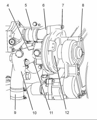
Illustration 79 |
|
4. Loosen the hose clamps and disconnect hose (9). |
|
g01391599 |
|
Illustration 78 |
|
5. Remove bolts (11) and remove connection (10). Remove O-ring seal (4) (not shown) from water pump (12). |
|
2. Remove bolts (1). Remove water temperature regulator housing (2) as a unit. Remove the O-ring seal from the water temperature regulator housing. |
|
6. Loosen the hose clamps and slide hose (5) toward connection (6). Remove bolts (7) and remove the connection from water pump (12). Remove the O-ring seal from the connection. |
|
3. Remove tube assembly (3). Remove the O-ring |
|
seals from the tube assembly. |
|
7. Remove bolts (8). |
|
8. Remove water pump (12). |
|
g01391623 |
|
Illustration 80 |
|
This document has been printed from SPI². Not for Resale |
![]()
![]()
![]()
![]()
![]()
![]()
![]()
|
KENR6906 |
|
37 Disassembly and Assembly Section |
|
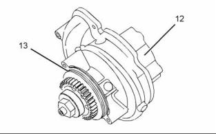
9. Remove O-ring seal (13) from water pump (12). |
|
i02754794 |
|
Water Pump - Install |
|
Installation Procedure |
|
Table 18 |
|
Required Tools |
|
Tool |
|
Part Number |
|
Part Description |
|
Qty |
|
POWERPART Rubber Grease |
|
A |
|
218200221 |
|
1 |
|
NOTICE Keep all parts clean from contaminants. |
|
Contaminants may cause rapid wear and shortened component life. |
|
1. Ensure that all mating surfaces are clean and free from damage. |
|
g01384522 |
|
Illustration 82 |
|
3. Position water pump (12) on the engine and install bolts (8). Tighten the bolts to a torque of 55 N·m (41 lb ft). |
|
4. Install a new O-ring seal to connection (6). Loosely assemble hose (5) and the hose clamps to the connection. |
|
5. Position connection (6) on water pump (12) and install bolts (7). Tighten the bolts to a torque of 28 N·m (21 lb ft). |
|
6. Connect hose (5) to the oil cooler. Tighten the hose clamps securely. |
|
g01391623 |
|
Illustration 81 |
|
2. Install a new O-ring seal (13) to water pump (12). Lubricate the O-ring seal with Tooling (A). |
|
7. Install a new O-ring seal (4) (not shown) to water pump (12). Position connection (10) on the water pump and install bolts (11). Tighten the bolts to a torque of 28 N·m (21 lb ft). |
|
8. Connect hose (9) and tighten the hose clamps securely. |
|
This document has been printed from SPI². Not for Resale |
![]()
![]()
![]()
![]()

![]()
|
38 |
|
KENR6906 |
|
Disassembly and Assembly Section |
|
NOTICE Keep all parts clean from contaminants. |
|
Contaminants may cause rapid wear and shortened component life. |
|
1. Drain the coolant from the cooling system into a suitable container for storage or for disposal. Refer to Operation and Maintenance Manual, “Cooling System Coolant - Change”. |
|
g01391599 |
|
Illustration 83 |
|
9. Install new O-ring seals to tube assembly (3). Lubricate the O-ring seals with Tooling (A). |
|
10. Install tube assembly (3) to the water pump. |
|
11. Install a new O-ring seal to water temperature regulator housing (2). Align the water temperature regulator housing with tube assembly (3) and install the water temperature regulator housing. |
|
12. Install bolts (1). Tighten the bolts to a torque of |
|
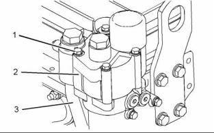
Illustration 84 |
|
g01390192 |
|
28 N·m (21 lb ft). |
|
Typical example |
|
13. Fill the cooling system. Refer to Operation and Maintenance Manual, “Cooling System Coolant - Change”. |
|
2. Remove bolts (1). |
|
3. Remove water temperature regulator housing (2) |
|
and tube assembly (3). |
|
End By: |
|
4. Remove the O-ring seals from tube assembly (3). |
|
a. Install the front plate and the support bracket. Refer to Disassembly and Assembly, “Front Plate - Install”. |
|
i02754796 Water Temperature Regulator Housing - Remove and Install |
|
Removal Procedure |
|
NOTICE |
|
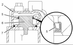
g01390160 |
|
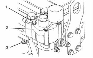
Illustration 85 |
|
Care must be taken to ensure that fluids are contained during performance of inspection, maintenance, test- ing, adjusting and repair of the product. Be prepared to collect the fluid with suitable containers before open- ing any compartment or disassembling any compo- nent containing fluids. |
|
5. Remove O-ring seal (7) from water temperature regulator housing (2). |
|
6. Remove water temperature regulator (6). |
|
7. If necessary, remove lip seal (5) from water temperature regulator housing (2). |
|
Dispose of all fluids according to local regulations and mandates. |
|
This document has been printed from SPI². Not for Resale |
![]()
![]()
![]()
![]()
![]()
![]()
![]()
![]()
|
KENR6906 |
|
39 Disassembly and Assembly Section |
|
3. Ensure that valve (9) is clean and free from restriction. If necessary, follow Steps 3.a and 3.b in order to install the valve to housing manifold (8). |
|
a. Install a new O-ring seal to valve (9). Apply Tooling (B) to the O-ring seal. |
|
b. Install valve (9) to housing manifold (8). |
|
g01390109 |
|
Illustration 86 |
|
8. If necessary, remove valve (9) from housing manifold (8). Remove the O-ring seal from the valve. |
|
Installation Procedure |
|
g01390160 |
|
Illustration 88 |
|
Table 19 |
|
Required Tools |
|
4. If necessary, install a new lip seal (5) to water temperature regulator housing (2). Use Tooling (A) to install the lip seal. |
|
Tool |
|
Part Number |
|
Part Description |
|
Qty |
|
A |
|
27610309 |
|
Seal Installer |
|
1 |
|
5. Install a new O-ring seal (7) to water temperature regulator housing (2). |
|
POWERPART Rubber Grease |
|
B |
|
21820221 |
|
1 |
|
6. Install water temperature regulator (6) to water temperature regulator housing (2). |
|
NOTICE Keep all parts clean from contaminants. |
|
Contaminants may cause rapid wear and shortened component life. |
|
1. Ensure that the mating surfaces of the water temperature regulator housing and the housing manifold are clean and free from damage. |
|
2. Check the water temperature regulator for correct operation. Refer to Systems Operation, Testing and Adjusting, “Water Temperature Regulator - Test” for the correct procedure. |
|
g01390192 |
|
Illustration 89 |
|
Typical example |
|
7. Install new O-ring seals to tube assembly (3). Apply Tooling (B) to the O-ring seals. Install the tube assembly to the water pump. |
|
8. Position water temperature regulator housing (2) and install bolts (1). Tighten the bolts to a torque of 28 N·m (21 lb ft). |
|
9. Fill the cooling system. Refer to Operation and Maintenance Manual, “Cooling System Coolant - Change”. |
|
g01390109 |
|
Illustration 87 |
|
This document has been printed from SPI². Not for Resale |