 English
 Espaol
 Franais
 阿拉伯
阿拉伯 中文
中文 Deutsch
 Italiano
 Português
 日本
日本 韩国
韩国 български
 hrvatski
 esky
esky Dansk
Dansk Nederlands
 suomi
suomi Ελληνικ
 印度
印度 norsk
norsk Polski
 Roman
Roman русский
 Svenska
Perkins珀金斯900 3.152柴油发动机U5MB0036曲轴瓦/85036 A连杆瓦供应商,Perkins珀金斯900 3.152柴油发动机U5MB0036曲轴瓦/85036 A连杆瓦技术价格规格咨询服务,Perkins珀金斯900 3.152柴油发动机U5MB0036曲轴瓦/85036 A连杆瓦零配件供应,Perkins珀金斯900 3.152柴油发动机U5MB0036曲轴瓦/85036 A连杆瓦售后服务中心,Perkins珀金斯900 3.152柴油发动机U5MB0036曲轴瓦/85036 A连杆瓦,Perkins珀金斯900 3.152柴油发动机U5MB0036曲轴瓦/85036 A连杆瓦详细的技术参数,

产品中心
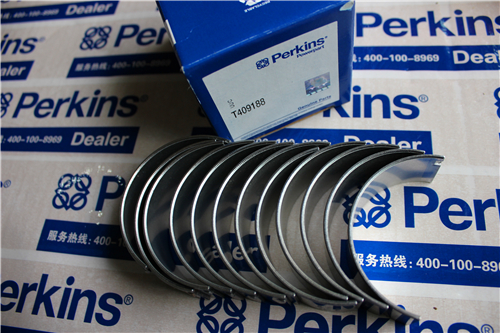
Perkins珀金斯900 3.152柴油发动机U5MB0036曲轴瓦/85036 A连杆瓦
详细描述
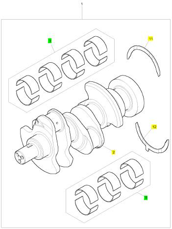
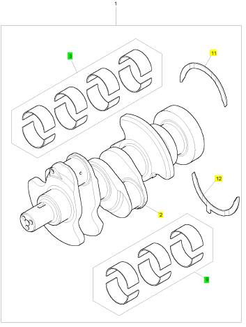
项目 零配件号码 最新件号 描述
2 1 曲柄轴
3 U5MB0036 1 U5MB0036 曲轴瓦总成
3 68084 1 U5MB0036 曲轴瓦总成
(3) U5MB0036A 1 U5MB0036A 曲轴瓦总成 -U/S
(3) U5MB0036B 1 U5MB0036B 曲轴瓦总成 -U/S
(3) U5MB0036C 1 U5MB0036C 曲轴瓦总成 -U/S
(3) 68084 A 1 U5MB0036A 曲轴瓦总成 -U/S
(3) 68084 B 1 U5MB0036B 曲轴瓦总成 -U/S
(3) 68084 C 1 U5MB0036C 曲轴瓦总成 -U/S
9 85036 1 85036 大头轴承总成
(9) 85036 A 1 85036 A 连杆瓦总成 -U/S
(9) 85036 B 1 85036 B 连杆瓦总成 -U/S
(9) 85036 C 1 85036 C 连杆瓦总成 -U/S
11 31137211 2 31137211 推力垫圈
(11) 31137212 2 31137212 推力垫圈 -特大号
12 31137221 2 31137221 推力垫圈
(12) 31137222 2 31137222 推力垫圈 -特大号
|
Disassembly and Assembly Section |
|
i02754798 |
|
Installation Procedure |
|
Engine Support (Front) - Remove and Install |
|
Table 21 |
|
Required Tools |
|
Tool |
|
Part Number |
|
Part Description |
|
Qty |
|
Guide Stud (M12 by 100mm) |
|
A |
|
- |
|
2 |
|
Removal Procedure |
|
Table 20 |
|
1. Ensure that the front of the engine is supported. |
|
Required Tools |
|
Tool |
|
Part Number |
|
Part Description |
|
Qty |
|
Guide Stud (M12 by 100mm) |
|
A |
|
- |
|
2 |
|
Start By: |
|
a. Remove the vibration damper and the crankshaft pulley. Refer to Disassembly and Assembly, “Vibration Damper and Pulley - Remove and Install”. |
|
1. Support the front of the engine. |
|
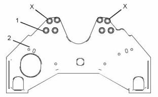
g01380895 |
|
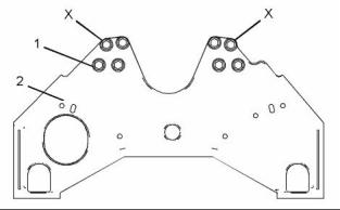
Illustration 91 |
|
2. Install Tooling (A) to positions (X) on the cylinder block. |
|
3. Install a suitable lifting device to engine support (2). The weight of engine support (2) is approximately 25 kg (55 lb). |
|
4. Use the lifting device to align engine support (2) with Tooling (A). Install the engine support to the cylinder block. |
|
5. Install bolts (1) finger tight. Remove Tooling (A) and install the remaining bolts. Tighten bolts to a torque of 100 N·m (74 lb ft). |
|
g01380895 |
|
Illustration 90 |
|
2. Attach a suitable lifting device to engine support (2). The weight of the engine support is approximately 25 kg (55 lb). |
|
End By: |
|
a. Install the vibration damper and the crankshaft pulley. Refer to Disassembly and Assembly, “Vibration Damper and Pulley - Remove and Install”. |
|
3. Remove bolts (1) from positions (X) and install Tooling (A) to positions (X). Remove the remaining bolts (1). |
|
4. Use the lifting device to remove engine support (2) from the cylinder block. |
|
5. Remove Tooling (A). |
|
This document has been printed from SPI². Not for Resale |
![]()

![]()
![]()

![]()
|
KENR6906 |
|
41 Disassembly and Assembly Section |
|
i02754801 |
|
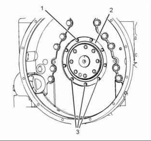
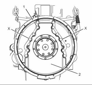
5. Remove the remaining bolts (1). Use the lifting device in order to remove flywheel (2). |
|
Flywheel - Remove |
|
Removal Procedure |
|
Table 22 |
|
Required Tools Part |
|
Tool |
|
Number |
|
Part Description |
|
Qty |
|
Guide Stud M16 by 120mm |
|
A |
|
- |
|
2 |
|
Start By: |
|
g01389418 |
|
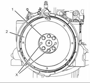
Illustration 93 |
|
Typical example |
|
a. Remove the electric starting motor. Refer to Disassembly and Assembly, “Electric Starting Motor - Remove and Install”. |
|
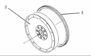
6. Inspect flywheel (2) and ring gear (3) for wear or damage. Replace any components that are worn or damaged. |
|
NOTICE |
|
Keep all parts clean from contaminants. |
|
7. To remove the ring gear, follow Steps 7.a and 7.b. a. Place flywheel (2) on a suitable support. |
|
Contaminants may cause rapid wear and shortened component life. |
|
Note: Identify the orientation of the teeth on the ring gear. |
|
b. Use a hammer and a punch in order to remove ring gear (3) from flywheel (2). |
|
i02754802 |
|
Flywheel - Install |
|
Installation Procedure |
|
Table 23 |
|
Required Tools |
|
Tool |
|
Part Number |
|
Part Description |
|
Qty |
|
Guide Stud M16 by 120mm |
|
A |
|
- |
|
2 |
|
g01383279 |
|
POWERPART Threadlock and Nutlock |
|
Illustration 92 |
|
B |
|
21820117 |
|
1 |
|
Typical example |
|
1. Attach a suitable lifting device to flywheel (2). Support the weight of the flywheel. The weight of the flywheel is approximately 50 kg (110 lb). |
|
NOTICE Keep all parts clean from contaminants. |
|
Contaminants may cause rapid wear and shortened component life. |
|
2. Use a suitable tool to lock flywheel (2). Loosen bolts (1). |
|
3. Remove two bolts (1) from positions (X). |
|
4. Install Tooling (A) to positions (X). |
|
This document has been printed from SPI². Not for Resale |
![]()

![]()
![]()
![]()
![]()


![]()
![]()
|
42 |
|
KENR6906 |
|
Disassembly and Assembly Section |
|
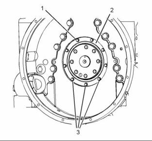
g01389418 |
|
Illustration 94 |
|
Always wear protective gloves when handling parts that have been heated. |
|
g01389447 |
|
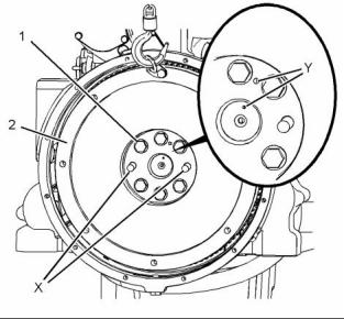
Illustration 95 |
|
1. If the ring gear was removed, follow Steps 1.a through 1.c in order to install a new ring gear to the flywheel. |
|
Typical example |
|
3. Install Tooling (A) to positions (X) on the crankshaft. |
|
a. Identify the orientation of the teeth on new ring gear (3). |
|
4. Install a suitable lifting device to flywheel (2). The weight of the flywheel is approximately 50 kg (110 lb). |
|
Note: The chamfered side of the ring gear teeth must face toward the starting motor when the flywheel is installed. This will ensure the correct engagement of the starting motor. |
|
5. Use the lifting device in order to position flywheel (2) onto Tooling (A). Ensure that Marks (Y) on the flywheel and on the crankshaft are aligned. |
|
b. Heat ring gear (3) in an oven to a maximum temperature of 316 °C (600 °F) prior to installation. |
|
6. Apply Tooling (B) to the threads of bolts (1). |
|
7. Install bolts (1). Remove Tooling (A). Install |
|
remaining bolts (1). |
|
Note: Do not use a torch to heat the ring gear. |
|
8. Use a suitable tool to prevent the flywheel from rotating. Tighten bolts (1) to a torque of 300 N·m (221 lb ft). |
|
c. Ensure that the orientation of ring gear (3) is correct and quickly install the ring gear onto flywheel (2). |
|
9. Remove the lifting device from flywheel (2). |
|
2. Inspect the crankshaft rear seal for leaks. If there are any oil leaks, replace the crankshaft rear seal. Refer to Disassembly and Assembly, “Crankshaft Rear Seal - Remove”. |
|
10. Check the runout of the flywheel. Refer to Systems Operations, Testing and Adjusting, “Flywheel - Inspect”. |
|
End By: |
|
a. Install the electric starting motor. Refer to Disassembly and Assembly, “Electric Starting Motor - Remove and Install”. |
|
This document has been printed from SPI². Not for Resale |
![]()
![]()
![]()
![]()
![]()
|
KENR6906 |
|
43 Disassembly and Assembly Section |
|
i02754803 |
|
i02754805 |
|
Crankshaft Rear Seal - Remove |
|
Crankshaft Rear Seal - Install |
|
Removal Procedure |
|
Installation Procedure |
|
Start By: |
|
Table 24 |
|
Required Tools Part |
|
a. Remove the flywheel. Refer to Disassembly and Assembly, “Flywheel - Remove”. |
|
Tool |
|
Number |
|
Part Description |
|
Qty |
|
POWERPART Threadlock and Nutlock |
|
NOTICE Keep all parts clean from contaminants. |
|
A |
|
21820117 |
|
1 |
|
Contaminants may cause rapid wear and shortened component life. |
|
NOTICE Keep all parts clean from contaminants. |
|
1. Ensure that the crankshaft flange and the housing for the crankshaft rear seal is clean, dry and free from damage. It is possible to reclaim a crankshaft flange that has a worn seal surface, or a damaged seal surface by installing a wear sleeve. Refer to Disassembly and Assembly, “Crankshaft Wear Sleeve (Rear) - Remove and Install” for more information. |
|
g01389635 |
|
Illustration 96 |
|
1. Remove bolts (1) and (3). |
|
2. Remove crankshaft rear seal (2). |
|
3. Remove the O-ring seal from crankshaft rear seal (2). |
|
g01389636 |
|
Illustration 97 |
|
This document has been printed from SPI². Not for Resale |
![]()
![]()
![]()
![]()

![]()
![]()
![]()
|
44 |
|
KENR6906 |
|
Disassembly and Assembly Section |
|
i02807660 Crankshaft Wear Sleeve (Rear) - Remove and Install |
|
Removal Procedure |
|
Start By: |
|
a. Remove the crankshaft rear seal. Refer to Disassembly and Assembly, “Crankshaft Rear Seal - Remove”. |
|
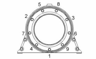
g01395750 |
|
Illustration 98 |
|
Tightening sequence for the crankshaft rear seal |
|
NOTICE |
|
Keep all parts clean from contaminants. |
|
2. Install a new O-ring seal to crankshaft rear seal (2). A new crankshaft rear seal is supplied with a plastic sleeve. Ensure that the plastic sleeve is squarely installed within the crankshaft rear seal. |
|
Contaminants may cause rapid wear and shortened component life. |
|
Note: Wear sleeves are used to reclaim worn seal surfaces or damaged seal surfaces. Wear sleeves are not original equipment. |
|
Note: The plastic sleeve is included in order to protect the lip of the seal as the seal is pushed over the crankshaft flange. |
|
1. Use a sharp tool to score a deep line across the crankshaft wear sleeve. |
|
Note: Do not lubricate the crankshaft rear seal or the crankshaft flange. The crankshaft rear seal must be installed dry. |
|
Note: Take care to avoid damaging the crankshaft. |
|
3. Align the plastic sleeve with the crankshaft flange. Ensure that the plastic sleeve is engaged onto the crankshaft flange. Push new crankshaft rear seal (2) squarely onto the crankshaft flange. |
|
2. Insert a thin blade between the crankshaft wear sleeve and the crankshaft below the scored line. The crankshaft wear sleeve will separate along the line. |
|
During this process, the plastic sleeve will be forced out of the crankshaft rear seal. Discard the plastic sleeve. |
|
3. Remove the crankshaft wear sleeve from the crankshaft. |
|
Installation Procedure |
|
4. Apply Tooling (A) to the threads of bolts (3). Install bolts (1) and (3). Tighten the bolts to a torque of 12 N·m (105 lb in) in the numerical sequence that is shown in Illustration 98. |
|
Table 25 |
|
Required Tools |
|
Tool |
|
Part Number 21820518 CVT0017 - |
|
Part Description |
|
Qty 1 |
|
End By: |
|
POWERPART Liquid Gasket |
|
A |
|
a. Install the flywheel. Refer to Disassembly and Assembly, “Flywheel - Install”. |
|
Installer |
|
1 |
|
B |
|
Bolt (M16 by 30 mm) |
|
3 |
|
NOTICE Keep all parts clean from contaminants. |
|
Contaminants may cause rapid wear and shortened component life. |
|
This document has been printed from SPI². Not for Resale |
![]()
![]()
![]()
![]()
![]()

![]()
![]()
|
KENR6906 |
|
45 Disassembly and Assembly Section |
|
Note: Wear sleeves are used to reclaim worn seal surfaces or damaged seal surfaces. Wear sleeves are not original equipment. |
|
Start By: |
|
a. Remove the electric starting motor. Refer to Disassembly and Assembly, “Electric Starting Motor - Remove and Install”. |
|
1. Ensure that the crankshaft is thoroughly clean and |
|
dry. Remove any areas of raised damage. |
|
b. Remove the flywheel. Refer to Disassembly and |
|
2. Apply a small continuous bead of Tooling (A) to the inner surface of the crankshaft wear sleeve. Apply the bead of Tooling (A) 5.00 mm (0.2 inch) from the chamfered end of the crankshaft wear sleeve. |
|
Assembly, “Flywheel - Remove”. |
|
NOTICE |
|
Care must be taken to ensure that fluids are contained during performance of inspection, maintenance, test- ing, adjusting and repair of the product. Be prepared to collect the fluid with suitable containers before open- ing any compartment or disassembling any compo- nent containing fluids. |
|
Dispose of all fluids according to local regulations and mandates. |
|
NOTICE Keep all parts clean from contaminants. |
|
Contaminants may cause rapid wear and shortened component life. |
|
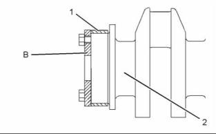
g01401603 |
|
Illustration 99 |
|
Sectional view of the crankshaft, the wear sleeve and the installation tool |
|
1. Support the rear of the engine. |
|
3. Align crankshaft wear sleeve (1) with crankshaft (2). Install Tooling (B) to crankshaft (2). Evenly tighten the bolts of Tooling (B) in order to install the crankshaft wear sleeve. |
|
4. Remove Tooling (B). |
|
End By: |
|
a. Install a new crankshaft rear seal. Refer to Disassembly and Assembly, “Crankshaft Rear Seal - Install”. |
|
i02754806 Flywheel Housing - Remove and Install |
|
g01383281 |
|
Illustration 100 |
|
Removal Procedure |
|
2. Attach a suitable lifting device to flywheel housing (2). The weight of the flywheel housing is approximately 25 kg (55 lb). |
|
Table 26 |
|
Required Tools |
|
Tool |
|
Part Number |
|
Part Description |
|
Qty |
|
3. Remove bolts (1) from positions (X). Install Tooling |
|
(A) to positions (X). |
|
Guide Stud (M14 by 100mm) |
|
A |
|
- |
|
2 |
|
4. Remove the remaining bolts (1). Use the lifting device to remove flywheel housing (2) from the cylinder block. |
|
This document has been printed from SPI². Not for Resale |
![]()
![]()

![]()
![]()
![]()
![]()
![]()
|
46 |
|
KENR6906 |
|
Disassembly and Assembly Section |
|
Note: It is not necessary to remove the dowels in the cylinder block that locate the flywheel housing. |
|
g01389649 |
|
Illustration 101 |
|
5. Remove O-ring seal (3) from housing (4). |
|
Installation Procedure |
|
g01383281 |
|
Illustration 103 |
|
Table 27 |
|
3. Apply Tooling (B) to the rear face of the cylinder |
|
block. |
|
Required Tools Part |
|
Note: The flywheel housing must be installed within ten minutes of applying Tooling (B). |
|
Tool |
|
Part Description |
|
Qty |
|
Number |
|
Guide Stud (M14 by 100mm) |
|
A B |
|
- |
|
2 1 |
|
4. Install Tooling (A) to positions (X) in the cylinder block. |
|
CH10879 |
|
Sealant |
|
5. Attach a suitable lifting device to flywheel housing (2). The weight of the flywheel housing is approximately 25 kg (55 lb). |
|
1. Ensure that the mating surfaces of the flywheel housing and the cylinder block are clean and free from damage. |
|
6. Use the lifting device to align flywheel housing (2) |
|
with Tooling (A). |
|
7. Install flywheel housing (2) to the cylinder block. |
|
8. Install bolts (1). Remove Tooling (A). Install the remaining bolts. Tighten the bolts to a torque of 160 N·m (118 lb ft). |
|
End By: |
|
a. Install the flywheel. Refer to Disassembly and Assembly, “Flywheel - Install”. |
|
b. Install the electric starting motor. Refer to Disassembly and Assembly, “Electric Starting Motor - Remove and Install”. |
|
g01389649 |
|
Illustration 102 |
|
2. Install a new O-ring seal (3) to housing (4). |
|
This document has been printed from SPI². Not for Resale |