 English
 Espaol
 Franais
 阿拉伯
阿拉伯 中文
中文 Deutsch
 Italiano
 Português
 日本
日本 韩国
韩国 български
 hrvatski
 esky
esky Dansk
Dansk Nederlands
 suomi
suomi Ελληνικ
 印度
印度 norsk
norsk Polski
 Roman
Roman русский
 Svenska
Perkins珀金斯900 3.152柴油发动机曲柄轴总成U983574C供应商,Perkins珀金斯900 3.152柴油发动机曲柄轴总成U983574C技术价格规格咨询服务,Perkins珀金斯900 3.152柴油发动机曲柄轴总成U983574C零配件供应,Perkins珀金斯900 3.152柴油发动机曲柄轴总成U983574C售后服务中心,Perkins珀金斯900 3.152柴油发动机曲柄轴总成U983574C,Perkins珀金斯900 3.152柴油发动机曲柄轴总成U983574C详细的技术参数,

产品中心
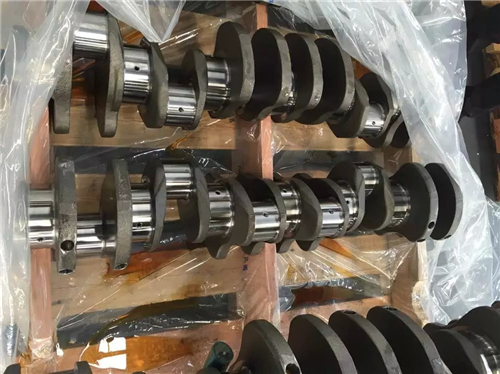
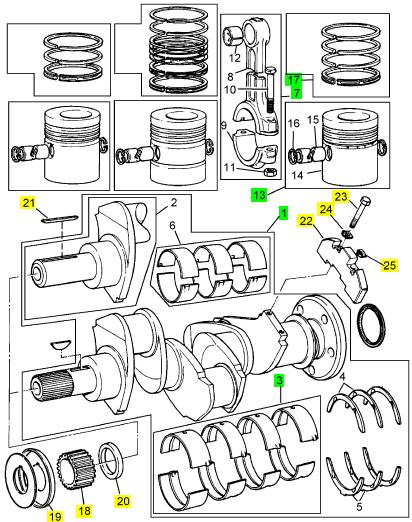
Perkins珀金斯900 3.152柴油发动机曲柄轴总成U983574C
详细描述
项目 零配件号码 最新件号 描述
1 ZZ90150 1 ZZ90150 曲柄轴总成 U983574C
1 ZZ90150 1 ZZ90150 曲柄轴总成 U983574C
(1) ZZ90150P 1 ZZ90150 曲柄轴总成 -交换
3 U5MB0014 1 U5MB0035 曲轴瓦总成 U983574C
7 ZZ90010 3 ZZ90010 连杆总成
13 U5LH0008 3 U5LH0008 活塞总成
13 68302 3 U5LH0008 活塞总成
13 89214 3 89214 活塞总成
(13) U5LL0040 3 U5LL0040 活塞总成
17 41158065 3 41158065 活塞环总成
18 31163493 1 31163495 曲柄轴传动机构
19 33176308 1 33176308 凸缘
20 33125151 1 33125151 间隔器
21 36271704 1 36271704 半圆键
22 31328242 2 31328242 重量
23 2185189 4 2185189 螺旋
24 31731515 2 21826055 垫圈 30/11/94
25 31731516 2 31731516 垫圈 30/11/94
|
Vibration Damper and Pulley - Remove and Install |
|
Removal Procedure |
|
Table 28 |
|
Required Tools |
|
Tool |
|
Part Number |
|
Part Description |
|
Qty |
|
Guide Stud (M16 by 120mm) |
|
A |
|
- |
|
2 |
|
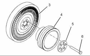
g01380897 |
|
Illustration 105 |
|
2. Remove the V-belts from crankshaft pulley (4). Temporarily secure the V-belts in a position that is clear of vibration damper (3). |
|
Start By: |
|
a. Remove the fan. Refer to Disassembly and |
|
Assembly, “Fan - Remove and Install”. |
|
3. Remove two bolts (6). Install Tooling (A). 4. Remove the remaining bolts (6) and spacer (5). 5. Remove crankshaft pulley (4). |
|
NOTICE Keep all parts clean from contaminants. |
|
Contaminants may cause rapid wear and shortened component life. |
|
6. Install a suitable lifting device to vibration damper (3). The weight of the vibration damper is approximately 36 kg (79 lb). Make a temporary mark in order to show the front of the vibration damper for installation. |
|
7. Use the lifting device to remove vibration damper (3) from the crankshaft. |
|
8. Remove Tooling (A) from the crankshaft. |
|
Installation Procedure |
|
Table 29 |
|
Required Tools |
|
Tool |
|
Part Number |
|
Part Description |
|
Qty |
|
Guide Stud |
|
A |
|
- |
|
2 |
|
(M16 by 120mm) NOTICE |
|
Keep all parts clean from contaminants. |
|
Contaminants may cause rapid wear and shortened component life. |
|
NOTICE |
|
Thoroughly inspect the viscous damper for signs of leakage or for signs of a dented (damaged) case. Either of these conditions can cause the weight to make contact with the case. This can affect the vis- cous damper’s operation. |
|
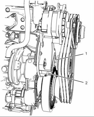
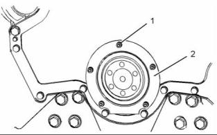
g01417120 |
|
Illustration 104 |
|
1. Loosen nut (1) that locks the position of the belt tightener. Rotate bolt (2) in order to release the tension on the V-belts. |
|
This document has been printed from SPI². Not for Resale |
![]()

![]()
![]()
![]()
![]()

![]()
![]()
![]()
![]()
|
48 |
|
KENR6906 |
|
Disassembly and Assembly Section |
|
1. Inspect the components for damage. Replace any components that are damaged. |
|
2. Inspect the crankshaft front seal for leaks. If necessary, replace the crankshaft front seal. Refer to Disassembly and Assembly, “Crankshaft Front Seal - Remove”. |
|
3. Install Tooling (A) to the crankshaft. |
|
g01380897 |
|
Illustration 106 |
|
4. Install a suitable lifting device to vibration damper (3). The weight of the vibration damper is approximately 36 kg (79 lb). |
|
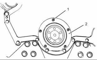
g01417120 |
|
Illustration 107 |
|
5. Use the lifting device to align vibration damper (3) with Tooling (A). Install the vibration damper to the crankshaft. |
|
9. Position the V-belts on the crankshaft pulley and the pulley of the belt tightener. |
|
10. Rotate bolt (2) in order to adjust the tension of the V-belts. Refer to Operation and Maintenance Manual, “Belts - Inspect/Adjust/Replace”. |
|
Note: Ensure correct orientation of the vibration damper. |
|
6. Remove the lifting device. |
|
11. Tighten nut (1) in order to lock the position of the belt tightener. |
|
7. Install crankshaft pulley (4) and spacer (5). |
|
End By: |
|
8. Install bolts (6). Remove Tooling (A) and install the remaining bolts (6). Tighten the bolts to a torque of 240 N·m (177 lb ft). |
|
a. Install the fan. Refer to Disassembly and Assembly, “Fan - Remove and Install”. |
|
i02754808 Crankshaft Front Seal - Remove |
|
Removal Procedure |
|
Start By: |
|
a. Remove the vibration damper and the crankshaft pulley. Refer to Disassembly and Assembly, “Vibration Damper and Pulley - Remove and Install”. |
|
This document has been printed from SPI². Not for Resale |
![]()
![]()

![]()

|
KENR6906 |
|
49 Disassembly and Assembly Section |
|
NOTICE Keep all parts clean from contaminants. |
|
Contaminants may cause rapid wear and shortened component life. |
|
g01383288 |
|
Illustration 109 |
|
g01383288 |
|
Illustration 108 |
|
1. Remove nuts (1). |
|
2. Remove crankshaft front seal (2). |
|
3. Remove the O-ring seal from crankshaft front seal (2). |
|
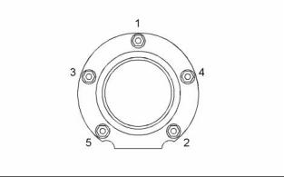
g01132632 |
|
Illustration 110 |
|
i02754809 |
|
Tightening sequence for the crankshaft front seal |
|
Crankshaft Front Seal - Install |
|
2. Install a new O-ring seal to crankshaft front seal (2). A new crankshaft front seal is supplied with a plastic sleeve. Ensure that the plastic sleeve is squarely installed within the crankshaft front seal. |
|
Installation Procedure |
|
Note: The plastic sleeve is included in order to protect the lip of the seal as the seal is pushed over the crankshaft flange. |
|
NOTICE Keep all parts clean from contaminants. |
|
Contaminants may cause rapid wear and shortened component life. |
|
Note: Do not lubricate the crankshaft front seal or the crankshaft flange. The crankshaft front seal must be installed dry. |
|
1. Ensure that the crankshaft flange and the front cover are clean, dry and free from damage. |
|
3. Align the plastic sleeve with the crankshaft flange. Ensure that the plastic sleeve is engaged onto the crankshaft flange. Push new crankshaft front seal (2) squarely onto the crankshaft flange. |
|
During this process, the plastic sleeve will be forced out of the crankshaft front seal. Discard the plastic sleeve. |
|
4. Install nuts (1). Tighten the nuts to a torque of 12 N·m (105 lb in) in the numerical sequence that is shown in Illustration 110. |
|
This document has been printed from SPI². Not for Resale |
![]()
![]()
![]()
![]()
![]()
![]()
![]()
![]()
|
50 |
|
KENR6906 |
|
Disassembly and Assembly Section |
|
End By: |
|
Installation Procedure |
|
a. Install the vibration damper and the crankshaft pulley. Refer to Disassembly and Assembly, “Vibration Damper and Pulley - Remove and Install”. |
|
Table 31 |
|
Required Tools |
|
Tool |
|
Part Number 21820518 CVT0018 - |
|
Part Description |
|
Qty 1 |
|
POWERPART Liquid Gasket |
|
A |
|
i02810672 |
|
Installer |
|
1 |
|
Crankshaft Wear Sleeve (Front) - Remove and Install |
|
B |
|
Bolt (M16 by 30 mm) |
|
3 |
|
NOTICE |
|
Keep all parts clean from contaminants. |
|
Removal Procedure |
|
Contaminants may cause rapid wear and shortened component life. |
|
Table 30 |
|
Required Tools Part |
|
Note: Wear sleeves are used to reclaim worn seal surfaces or damaged seal surfaces. Wear sleeves are not original equipment. |
|
Tool |
|
Number |
|
Part Description |
|
Qty |
|
A |
|
- |
|
Puller |
|
1 |
|
1. Ensure that the crankshaft is thoroughly clean and dry. Remove any areas of raised damage. |
|
Start By: |
|
a. Remove the crankshaft front seal. Refer to Disassembly and Assembly, “Crankshaft Front Seal - Remove”. |
|
2. Apply a small continuous bead of Tooling (A) to the inner surface of the crankshaft wear sleeve. Apply the bead of Tooling (A) 5.00 mm (0.2 inch) from the chamfered end of the crankshaft wear sleeve. |
|
NOTICE |
|
Keep all parts clean from contaminants. |
|
Contaminants may cause rapid wear and shortened component life. |
|
Note: Wear sleeves are used to reclaim worn seal surfaces or damaged seal surfaces. Wear sleeves are not original equipment. |
|
1. Use a sharp tool to score a deep line across the crankshaft wear sleeve. |
|
Note: Take care to avoid damaging the crankshaft. |
|
g01402019 |
|
Illustration 111 |
|
2. Insert a thin blade between the crankshaft wear sleeve and the crankshaft below the scored line. The crankshaft wear sleeve will separate along the line. |
|
Sectional view of the crankshaft, the wear sleeve and the installation tool |
|
3. Align crankshaft wear sleeve (1) with crankshaft (2). Install Tooling (B) to crankshaft (2). Evenly tighten the bolts of Tooling (B) in order to install the crankshaft wear sleeve. |
|
3. Remove the crankshaft wear sleeve from the crankshaft. |
|
4. Remove Tooling (B). |
|
This document has been printed from SPI². Not for Resale |