 English
 Espaol
 Franais
 阿拉伯
阿拉伯 中文
中文 Deutsch
 Italiano
 Português
 日本
日本 韩国
韩国 български
 hrvatski
 esky
esky Dansk
Dansk Nederlands
 suomi
suomi Ελληνικ
 印度
印度 norsk
norsk Polski
 Roman
Roman русский
 Svenska
Perkins柴油发动机2674227涡轮增压器供应商,Perkins柴油发动机2674227涡轮增压器技术价格规格咨询服务,Perkins柴油发动机2674227涡轮增压器零配件供应,Perkins柴油发动机2674227涡轮增压器售后服务中心,Perkins柴油发动机2674227涡轮增压器,Perkins柴油发动机2674227涡轮增压器详细的技术参数,

产品中心
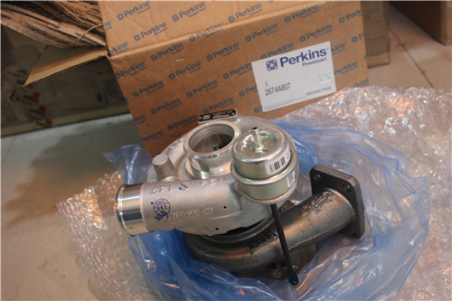
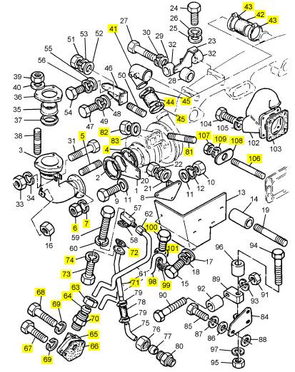
Perkins柴油发动机2674227涡轮增压器
详细描述
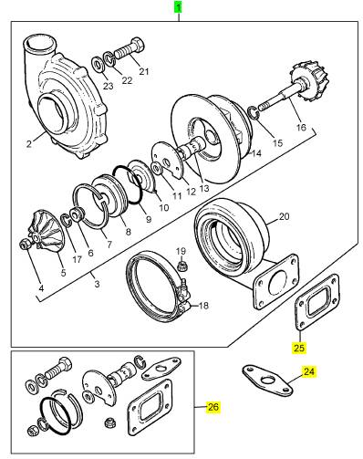
项目 零配件号码 最新件号 描述
1 2674227 1 2674227 涡轮增压器
24 2 密合垫
25 36885008 1 36885008 密合垫 -涡轮增压器
26 26740561 1 26740561 修补总成 -涡轮增压器
26 26740688 1 26740688 修补总成 -涡轮增压器
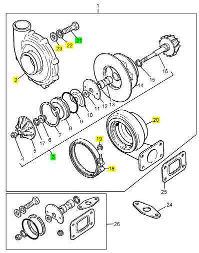
项目 零配件号码 最新件号 描述
2 1 盖
3 26740599 1 26740599 心
3 28730822 1 28730822 心
18 26740541 1 26740541 砂箱夹
18 28730843 1 28730843 砂箱夹
19 26740712 1 26740712 螺帽
19 28730844 1 28730844 锁紧螺母
20 1 壳
21 26740538 8 26740538 螺旋
21 28730845 8 28730845 螺旋
22 26740713 8 26740713 垫圈
23 8 垫圈
23 26740537 8 26740537 垫圈
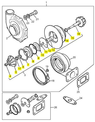
项目 零配件号码 最新件号 描述
4 1 螺帽
5 26740553 1 26740553 轮
5 28730824 1 28730824 轮
6 1 活塞
7 1 CIRCLIP
7 1 CIRCLIP
8 1 轮
9 1 O 圈
10 1 推力垫圈
11 1 垫圈
12 1 推力板
13 1 轴承
14 26740559 1 26740559 壳
14 28730823 2 28730823 壳
15 2 圈
16 26740558 1 26740558 轴
16 28730819 1 28730819 轮
17 1 圈
项目 零配件号码 最新件号 描述
4 33415508 1 33415508 密合垫
5 0827607 6 0827607 图钉
6 2188134 6 2188134 螺帽
7 0920053 6 0920053 垫圈
41 37741321 1 37741321 构件
42 0200033 1 0200033 水管
43 21825201 2 21825201 夹
44 33823411 1 33823411 连接
45 21825200 2 21825194 夹
63 0576116 1 0576116 螺帽
64 0566007 1 0566007 橄榄
65 37735101 1 检查历史 承接器
66 36861448 1 36862206 密合垫 - 滤油器的冒口
67 0746610 1 0746610 螺旋
68 0096634 1 0096634 螺旋
69 0920055 2 0920055 垫圈
70 0206008 1 0206008 管套节
71 35712151 1 35712151 管
72 36832151 1 3683 D006 密合垫
73 0748523 2 0748523 螺旋
74 0920054 2 0920054 垫圈
81 0827809 4 0827809 图钉
82 2188135 4 2188135 螺帽
83 0920004 4 0920004 垫圈
98 41243041 1 41243041 管
99 36832138 1 36832138 密合垫
100 0748414 2 0748414 固定螺钉
101 0920053 2 0920053 垫圈
106 0826244 1 0826244 图钉
107 0576002 1 0576002 螺帽
108 36151505 1 36151505 垫圈
109 0920053 1 0920053 垫圈
110 0826242 2 0826242 图钉
111 0576002 2 0576002 螺帽
112 36151505 2 36151505 垫圈
113 0920053 2 0920053 垫圈
项目 零配件号码 最新件号 描述
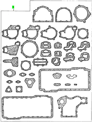
1 U5LB1224 1 U5LB1224 密合垫总成 -底
项目 零配件号码 最新件号 描述
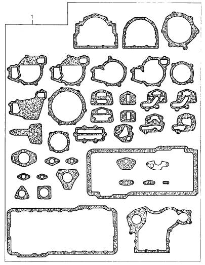
5 3681 P032 1 3681 P032 密合垫 - 正时齿轮箱
6 36826124 1 36826124 密合垫
7 36817166 1 36817166 密合垫 - 再操作系统壳
8 3681 T018 1 3681 T018 密合垫 - 油的密封壳
9 36862206 1 36862206 密合垫 - 滤油器的冒口
11 36822143 1 36822143 密合垫
12 36846424 1 36846424 密合垫
13 3685 R007 1 3685 R007 密合垫 - 提升泵
14 36862226 1 36862226 密合垫 - 提升泵
15 36866474 1 36866474 密合垫
19 3687 M024 1 3687 M024 密合垫 - 水的泵
20 36867227 1 36867227 密合垫 - 水的连接
21 3684 C002 1 3684 C002 密合垫
23 36832153 1 36832153 密合垫
28 3687 H017 1 3687 H017 密合垫 - 燃料的 INJ 泵
29 2415813 1 2415813 密封 - O 的圈
30 2415715 3 2415715 密封 - O 的圈
31 36816731 1 U5MK0398 密合垫 -油底壳
32 21826373 1 21826373 密合垫 -油底壳
33 36866426 1 36866426 密合垫
项目 零配件号码 最新件号 描述
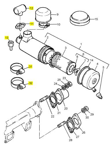
11 2651854 1 2651854 凸缘
12 2651852 1 2651852 指压计
13 33531326 1 33531326 承接器
31 2481905 2 2481905 夹
32 2481909 2 2481909 水管夹
|
End By: |
|
a. Install a new crankshaft front seal. Refer to Disassembly and Assembly, “Crankshaft Front Seal - Install”. |
|
i02754810 |
|
Front Cover - Remove |
|
Removal Procedure |
|
g01392333 |
|
Start By: |
|
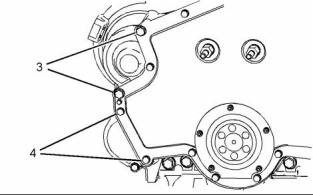
Illustration 113 |
|
Typical example |
|
a. Remove the front plate. Refer to Disassembly and |
|
Assembly, “Front Plate - Remove”. |
|
2. Remove bolts (3) and (4). |
|
b. Remove the crankshaft front seal. Refer to Disassembly and Assembly, “Crankshaft Front Seal - Remove”. |
|
NOTICE Keep all parts clean from contaminants. |
|
Contaminants may cause rapid wear and shortened component life. |
|
NOTICE |
|
Care must be taken to ensure that fluids are contained during performance of inspection, maintenance, test- ing, adjusting and repair of the product. Be prepared to collect the fluid with suitable containers before open- ing any compartment or disassembling any compo- nent containing fluids. |
|
Dispose of all fluids according to local regulations and |
|
mandates. |
|
g01395833 |
|
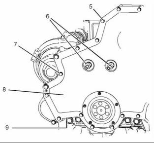
Illustration 114 |
|
3. Remove bolts (5), fasteners (6) and bolt (7). |
|
4. Remove front cover (8) and joint (9) (not shown). |
|
i02754811 |
|
Front Cover - Install |
|
Installation Procedure |
|
Table 32 |
|
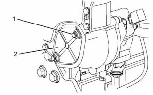
g01395819 |
|
Illustration 112 |
|
Required Tools Part |
|
1. Remove bolts (1) and plate (2). Remove the O-ring seal from the front housing. |
|
Tool |
|
Number |
|
Part Description |
|
Qty |
|
POWERPART Threadlock and Nutlock |
|
A |
|
21820117 |
|
1 |
|
This document has been printed from SPI². Not for Resale |
![]()
![]()
![]()
![]()
![]()
![]()

![]()
![]()


|
52 |
|
KENR6906 |
|
Disassembly and Assembly Section |
|
5. Install bolts (3). Tighten the bolts to a torque of |
|
55 N·m (41 lb ft). |
|
NOTICE |
|
Keep all parts clean from contaminants. |
|
6. Apply Tooling (A) to bolt (7). 7. Install bolts (4), (5) and (7). |
|
Contaminants may cause rapid wear and shortened component life. |
|
8. Tighten bolts (4), (5) and (7) to a torque of 28 N·m (21 lb ft). |
|
1. Ensure that the front cover and the mating surface of the front housing are clean and free from damage. |
|
g01395819 |
|
Illustration 117 |
|
9. Install a new O-ring seal to the front housing. Position plate (2) and install bolts (1). Tighten the bolts to a torque of 55 N·m (41 lb ft). |
|
End By: |
|
a. Install a new crankshaft front seal. Refer to Disassembly and Assembly, “Crankshaft Front Seal - Install”. |
|
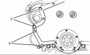
g01395833 |
|
Illustration 115 |
|
b. Install the front plate. Refer to Disassembly and Assembly, “Front Plate - Install”. |
|
i02754812 |
|
Gear Group (Front) - Remove |
|
Removal Procedure |
|
Table 33 |
|
g01392333 |
|
Illustration 116 |
|
Required Tools Part |
|
Typical example |
|
2. Align a new joint (9) (not shown) with the dowels in the front housing. Install the joint. |
|
Tool |
|
Number CH11148 27610286 CVT0015 |
|
Part Description Crankshaft Turning Tool Timing Pin (Crankshaft) Adapter |
|
Qty 1 |
|
A |
|
3. Align front cover (8) with the dowels in the front housing. Install the front cover. |
|
1 |
|
B |
|
1 |
|
4. Install fasteners (6). Tighten the fasteners to a torque of 100 N·m (74 lb ft). |
|
This document has been printed from SPI². Not for Resale |
![]()
![]()
![]()
![]()
![]()
![]()

|
KENR6906 |
|
53 Disassembly and Assembly Section |
|
Start By: |
|
a. Remove the front cover. Refer to Disassembly and Assembly, “Front Cover - Remove”. |
|
b. Remove the valve mechanism cover. Refer to Disassembly and Assembly, “Valve Mechanism Cover - Remove and Install”. |
|
NOTICE Keep all parts clean from contaminants. |
|
Contaminants may cause rapid wear and shortened component life. |
|
1. Use Tooling (A) in order to rotate the crankshaft so that number one piston is at the top center position on the compression stroke. Refer to Systems Operation, Testing and Adjusting, “Finding Top Centre Position for No.1 Piston”. |
|
g01400788 |
|
Illustration 119 |
|
2. Install Tooling (B) to the flywheel housing. Use Tooling (B) in order to align the flywheel in the correct position. Refer to Systems Operation, Testing and Adjusting, “Finding Top Centre Position for No.1 Piston”. |
|
4. Ensure that the timing marks on gears (3), (4) and |
|
(5) are aligned. |
|
g01400786 |
|
Illustration 120 |
|
g01393906 |
|
Illustration 118 |
|
5. Follow Step 5.a through Step 5.c in order to |
|
remove idler gear (4). |
|
3. Loosen nuts (1) on all rocker arms . Unscrew adjusters (2) on all rocker arms until all valves are fully closed. |
|
a. Remove bolt (8). |
|
b. Carefully use a pry bar in order to remove gear (4) and hub (10). |
|
Note: Failure to ensure that ALL adjusters are fully unscrewed can result in contact between the valves and pistons. |
|
c. Remove hub (10) from gear (4). |
|
6. Follow Step 6.a through Step 6.c in order to remove idler gear (6). |
|
a. Remove bolt (7). |
|
b. Carefully use a pry bar in order to remove gear (6) and hub (9). |
|
c. Remove hub (9) from gear (6). |
|
This document has been printed from SPI². Not for Resale |