English
 Espaol
 Franais
 阿拉伯
阿拉伯 中文
中文 Deutsch
 Italiano
 Português
 日本
日本 韩国
韩国 български
 hrvatski
 esky
esky Dansk
Dansk Nederlands
 suomi
suomi Ελληνικ
 印度
印度 norsk
norsk Polski
 Roman
Roman русский
 Svenska
珀金斯3012发动机维修技术供应商,珀金斯3012发动机维修技术技术价格规格咨询服务,珀金斯3012发动机维修技术零配件供应,珀金斯3012发动机维修技术售后服务中心,珀金斯3012发动机维修技术,珀金斯3012发动机维修技术详细的技术参数,

产品中心
珀金斯3012发动机维修技术
详细描述
|
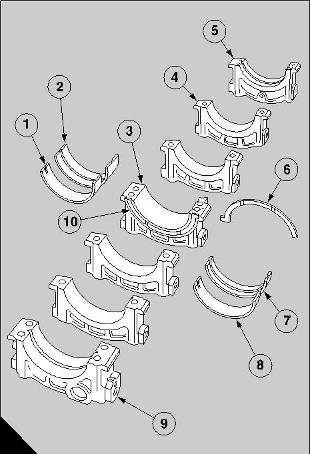
Piston and connecting rod assembly |
|
To remove and to fit |
|
13-3 |
|
Special tools: |
|
Guide pin, 21825 843 Retainers, 21825 844 |
|
To remove |
|
1 Disconnect the batteries, stop the supply of the fuel and drain the engine lubricating oil from the sump |
|
2 Drain the cooling system. |
|
3 Remove the relevant cylinder head, operation 12-9. |
|
4 Remove the lubricating oil sump, operation 19-1 or, for new engines, operation 19-5. |
|
5 For early engines, remove the sump adaptor, operation 19-3. |
|
6 If necessary, release the bolts which retain the lubricating oil pump and remove the lubricating oil pump, operation 19-7. |
|
7 Hold the relevant cylinder liner with the retainers, 21825 844, as necessary. |
|
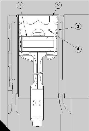
8 Turn the crankshaft until the selected assembly of the piston and connecting rod is at the bottom of its stroke and remove the nuts of the big end bolts. Remove the bearing cap and fit the guide pin, 21825 843, on to one of the big end bolts. Push carefully the assembly out through the top of the cylinder. |
|
Caution: There is a danger that the connecting rod could fall against the cylinder liner and break it. The use of the guide pin, 21825 843, ensures that this damage cannot occur. |
|
Perkins Engines Company Limited |
|
65 |
|
This document has been printed from SPI². Not for Resale |
![]()
![]()
![]()
![]()
![]()
|
13 To fit |
|
Special tools: |
|
Height gauge, 21825 782 Guide pin, 21825 843 |
|
Retainer, 21825 844 |
|
Piston ring compressor, 21825 845 |
|
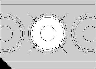
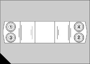
1 Turn the crankshaft until the relevant crank pin is at BDC. Check that the upper half bearing of the big end is in its position on the connecting rod. Set the gaps of the piston rings in the positions shown (A) if the pistons have four rings. If the pistons have three rings, set the gaps as shown (B). Apply oil to the crank pin, the upper half bearing and the piston, and slide the piston ring compressor, 21825 845, over the lower end of the piston with the tapered section against the piston rings. Fit the guide pin, 21825 843, onto one of the bolts of the big end bearing (C). It is recommended that new bolts and nuts are used. When the bolts are fitted, press carefully each bolt into the connecting rod until the bolt head is fully against the machined face of the connecting rod. |
|
A |
|
12 |
|
Caution: There is a danger that the connecting rod could fall against the cylinder liner and break it. The use of the guide pin, 21825 843, ensures that this damage cannot occur. |
|
B |
|
13 |
|
Caution: If the old bolts and nuts have been used for the connecting rod, they must first be inspected, for signs of distortion of the threads, for stress, or for indications of stretch, etc. Renew all bolts and nuts that could be defective. |
|
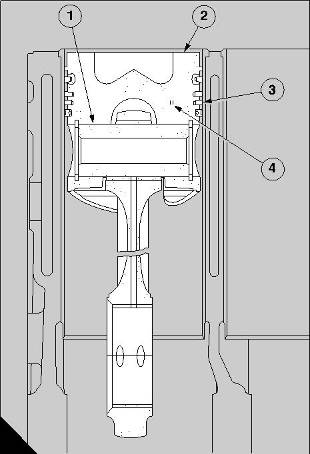
2 Fit carefully the assembly of the piston and the connecting rod into its liner. Ensure that the cutout in the lower wall of the piston is in the correct |
|
relationship to the piston cooling jet assembly. Use the guide pin to pull the assembly through the piston ring compressor and into the cylinder liner. Ensure that the piston ring compressor is held, and does not fall when it becomes free. Continue to pull the assembly until the big end bearing is fitted on the crank pin. If the piston and the connecting rod are assembled correctly, the chamfer on the edge of the bore in the big end is toward the crankshaft web. Ensure that there is clearance between the piston and the cooling jet. |
|
Caution: During this operation, do not damage the bearing surfaces of the crank pin and the half bearings of the big end. |
|
A |
|
194 |
|
66 |
|
Perkins Engines Company Limited |
|
This document has been printed from SPI². Not for Resale |
![]()
![]()
![]()
![]()

|
13 |
|
Caution: If a retainer, 21825 844, is removed to give a clearance for the piston ring compressor, it must be fitted again for each operation before the crankshaft is turned. |
|
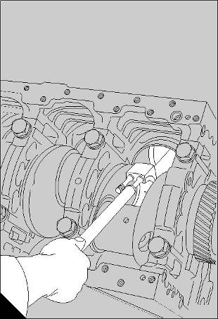
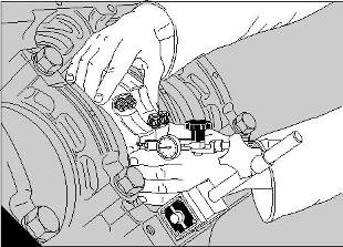
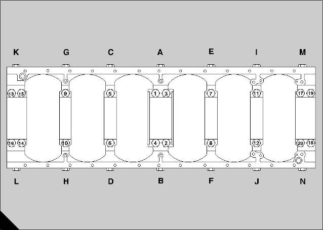
3 Fit and tighten the four nuts of the connecting rod, in the sequence shown (A) to 20 Nm (15 lbf ft) and then to 40 Nm (30 lbf ft). The final operation is to tighten them to 60 Nm (44 lbf ft). It is recommended that the new bolts and nuts are used. Lubricate lightly the threads and the contact faces before they are fitted to the connecting rods. |
|
Caution: The nuts of the connecting rod should be tightened gradually and evenly. During this operation avoid rapid or sudden movements of the torque wrench. |
|
A |
|
114 |
|
4 Ensure that the crankshaft turns freely. |
|
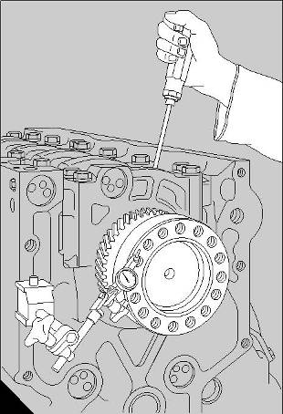
5 Check the end-float of the connecting rods with a dial test indicator, as shown (B). The clearance for each set of two connecting rods, between the big ends and their relevant crankshaft webs, must be 0,20 mm to 0,40 mm (0.008 to 0.016 in). |
|
6 Repeat the procedure for each assembly of a piston and a connecting rod. |
|
Check the clearance between the top face of the piston and the top face of the cylinder bank as follows: |
|
7 Put the setting plate of the height gauge, 21825 782, on a clean surface which is machined and put the base of the tool over the setting plate. Align the button of the dial gauge to make contact with the centre of the plate. Set the dial gauge to zero and tighten the locking screw. |
|
B |
|
197 |
|
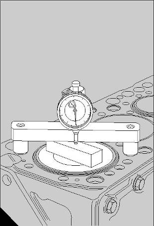
8 Turn the crankshaft until one of the pistons is almost at the top of its cylinder and move the setting plate to the top face of the piston. Put the base of the tool on the top face of the cylinder block, as shown (C). |
|
9 Continue to turn slowly the crankshaft, to allow the piston to pass TDC. As the piston passes TDC, make a note of the reading on the dial gauge; the maximum deflection of the pointer gives a minimum reading to indicate the clearance between the top face of the piston and the top face of the cylinder bank. The permissible clearance is from 0,31 to 0,38 mm (0.012 to 0.015 in). For engines manufactured from July 1998, fitted with piston number CV66887, the permissible clearance is from 0,31 to 0,75 mm (0.012 to 0.029 in). |
|
B |
|
198 |
|
Perkins Engines Company Limited |
|
67 |
|
This document has been printed from SPI². Not for Resale |
![]()
![]()
|
13 10 Check the clearance of each piston in the cylinders of ’A’ bank, then turn the crankcase until the cylinders of ’B’ bank are vertical. Repeat the procedure to check the clearance of each piston in the cylinders of ’B’ bank. |
|
Caution: If not enough clearance is shown on the dial gauge, the top face of the piston must be machined to remove the minimum amount of material which is necessary to give the correct clearance. This will not be necessary for engines manufactured after July 1998 fitted with the piston XCV66887. |
|
11 Fit the cylinder head, operation 12-9. |
|
12 Fit the lubricating oil pump if relevant, operation 19-7. |
|
13 For early engines, fit the sump adaptor, operation 19-3. |
|
14 Fit the lubricating oil sump, operation 19-1 or, for new engines, operation 19-5. |
|
15 Fill the sump to the correct level with engine lubricating oil and connect the supply of the fuel. |
|
16 Fill the cooling system. 17 Connect the batteries. |
|
To dismantle and to assemble |
|
13-4 |
|
To dismantle |
|
1 Remove the circlips which retain the gudgeon pin. |
|
2 Push the gudgeon pin out by hand to release the connecting rod. If the gudgeon pin is tight, heat the piston in a tank of warm water. Keep together each assembly. |
|
To assemble |
|
Before the connecting rod is assembled, check for dirt and debris in the passage for the lubricating oil |
|
and clean the passage with compressed air. 1 The gudgeon pin should be a push fit at 20°C (68°F). If it is tight in its bore in the piston, heat the piston in a tank of warm water. Remove the piston from the water and use a clean and suitable rag to dry the bore for the gudgeon pin. Fit one of the circlips into its groove in the bore. |
|
2 Give an application of clean engine lubricating oil to the small end bush, the gudgeon pin and the bore for the gudgeon pin. |
|
68 |
|
Perkins Engines Company Limited |
|
This document has been printed from SPI². Not for Resale |
![]()
![]()
![]()
![]()
|
13 |
|
3 Insert the small end of the connecting rod into the piston, and ensure that the cut-out in the lower wall of the piston is on the opposite side to the larger chamfer in the bore of the big end. |
|
4 Slide the gudgeon pin into the piston through the small end bush and fit the second circlip into its groove. |
|
Caution: When the big-end bolts are to be fitted, the flat surface, which is machined on the shoulder at the centre of each bolt, must be away from the bore of the big end. The half bearings will then engage correctly in the bore of the connecting rod. The shoulders of new bolts do not have the flat surfaces and special fitting instructions are not needed for them. |
|
Perkins Engines Company Limited |
|
69 |
|
This document has been printed from SPI². Not for Resale |
![]()
![]()
|
13 Piston rings |
|
To remove and to fit |
|
13-5 |
|
Special tools: |
|
Ring expander, 21825 793 |
|
To remove |
|
1 Put the top face of the piston on the bench and use the ring expander, 21825 793, with the location ring, 21825 874, to remove carefully each piston ring. Only increase the ring gaps enough to ensure that the ends of the rings do not damage the piston. Lift out the coil spring from the groove for the oil control ring. Keep the rings with their relevant piston. |
|
To fit |
|
1 Put the top face of the piston on the bench and lubricate the grooves for the piston rings. Use the ring expander, 21825 793, to fit carefully each piston ring in the sequence given below. Only increase the ring gaps enough to ensure that the ends of the rings do not damage the piston. |
|
2 Remove the coil spring from its oil control ring and fit it around the bottom piston ring groove, with the latch pin inside both ends of the spring, before the oil control ring is fitted to the piston. Ensure that the piston ring gap is at 180° to the latch pin. |
|
The sequence of the assembly of the rings is: |
|
Top |
|
- |
|
Barrel faced molybdenum surface |
|
Second |
|
- |
|
Chromium plated surface, counterbore toward top of piston |
|
Third |
|
- - |
|
'Ferrox' treated surface, counterbore toward top of piston |
|
Bottom |
|
Composite chromium plated oil control ring |
|
70 |
|
Perkins Engines Company Limited |
|
This document has been printed from SPI². Not for Resale |
![]()
![]()
![]()
![]()
![]()
|
13 |
|
Piston and rings |
|
Connecting rod |
|
To inspect |
|
13-6 To inspect |
|
13-7 |
|
1 Soak the components in a solvent, such as ’Maxan’ 1 Clean the assembly of each connecting rod in |
|
or ’Ardrox 667’, to remove the carbon. Wash the components in clean water and dry them with compressed air. |
|
kerosene or a degreasing solution, and then check for cracks in the rod, the big end cap and the big end bolts. |
|
2 Inspect the piston for wear, deep scratches, cracks Caution: It is recommended that the old bolts and |
|
and further damage. Check that the wear in each piston ring groove does not exceed the permissible limits. If necessary, check the grooves by the use of new piston rings. |
|
the old nuts of the assemblies of the connecting rods should be discarded. Fit always new nuts to new bolts and lubricate lightly the threads and the contact faces before they are fitted to the connecting rods. |
|
3 Inspect the piston rings for wear, deep scratches and signs of leakage. Discard the top ring if the surface has large holes or cavities, or if there are signs that the surface finish has started to break. Compare the surface with the surface of a new ring if necessary. |
|
2 The bolts and the nuts of the assemblies of the connecting rods must be inspected for signs of distortion of the threads, for stress or for stretch, etc. Renew all bolts which could be defective. |
|
3 Check the small end bush for wear, for roughness and for deep scratches. If a bush is damaged, it must be renewed. |
|
4 Inspect the spring which is behind the oil control ring. If the circumference of the spring is excessively decreased, the spring and the oil control ring must be renewed as a complete unit. |
|
4 Inspect the half bearings of the big end for cracks, for scratches and for contamination in the bearing surfaces. |
|
5 Check the gap of each piston ring in a new cylinder liner, or in a portion of the original cylinder liner which is not worn. Discard a piston ring with a gap which exceeds the limits given on page 73 or page 75. |
|
5 Check the alignment of the big end and of the small end of the connecting rod. Do not try to correct a connecting rod which is bent or twisted. |
|
Caution: When a new cylinder liner has been fitted, the piston rings must also be renewed. When a new piston ring is fitted into an original cylinder liner, the bore of the cylinder liner must be honed or lapped to break the glazed surface. |
|
6 Check for cracks in the gudgeon pin and check also its fit in the piston. The gudgeon pin should be a push fit at 20°C (68°F). If the gudgeon pin is loose in its bore, the assembly must be renewed. |
|
Caution: An assembly of a piston and its gudgeon pin must be renewed if the components do not conform to the limits given in Fits and clearances at the end of this section. If it is necessary to renew a piston, it is also necessary to ensure that the clearance is correct between the top of the new piston and the top face of the cylinder bank by the use of the height gauge, 21825 782, operation 13-3. |
|
Perkins Engines Company Limited |
|
71 |
|
This document has been printed from SPI². Not for Resale |
![]()
![]()
![]()
![]()
![]()
![]()
,
|
13 Fits and clearances - Pistons and connecting rods |
|
Pistons - 4 rings |
|
Gudgeon pin in piston (A1) |
|
(Gudgeon pin to be push fit at 20°C) |
|
Bore in piston (new). . . . . . . . . . . . . . . . . . . . . . . . . . . . . . . . . . . . 54,999 to 55,004 mm (2.1653 to 2.1655 in) Gudgeon pin diameter (new) . . . . . . . . . . . . . . . . . . . . . . . . . . . . . 54,995 to 55,000 mm (2.1652 to 2.1654 in) Gudgeon pin in piston - clearance (new) . . . . . . . . . . . . . . . . .-0,001 to +0,009 mm (-0.00004 to +0.00036 in) |
|
Top groove in piston |
|
(wedge shaped for top ring CV 5907) |
|
Diameter over 3,302 mm (0.1300 in) dia. Rollers . . . . . . . . . . . 136,073 to 135,855 mm (5.3572 to 5.3486 in) |
|
Piston clearance at TDC (A2) |
|
Top of piston below top face of crankcase. . . . . . . . . . . . . . . . . . . . . . . 0,310 to 0,380 mm (0.012 to 0.015 in) (Machine top face of piston to obtain correct clearance) |
|
Piston rings |
|
Clearances of piston rings in grooves (A3) |
|
Top ring CV 5907 (wedge shaped - new) . . . . . . . . . . . . . . . . . . . . . . . . . . . . . . Refer to ring gap dimensions Second ring OE41689 (new) . . . . . . . . . . . . . . . . . . . . . . . . . . . . . 0,0635 to 0,1016 mm (0.0025 to 0.0040 in) Maximum permissible worn clearance. . . . . . . . . . . . . . . . . . . . . . . . . . . . . . . . . . . . . . . . 0,152 mm (0.006 in) |
|
A |
|
121 |
|
72 |
|
Perkins Engines Company Limited |
|
This document has been printed from SPI². Not for Resale |
![]()
![]()
|
13 |
|
Clearances of piston rings in grooves (continued) |
|
Refer to the illustration (A) on page 72. |
|
Third ring OE 42641 (new) . . . . . . . . . . . . . . . . . . . . . . . . . . . . . . 0,0635 to 0,1143 mm (0.0025 to 0.0045 in) Maximum permissible worn clearance . . . . . . . . . . . . . . . . . . . . . . . . . . . . . . . . . . . . . . . 0,152 mm (0.006 in) |
|
Oil control ring CV 5908 (new) . . . . . . . . . . . . . . . . . . . . . . . . . . . . . 0,049 to 0,086 mm (0.0019 to 0.0034 in) Maximum permissible worn clearance . . . . . . . . . . . . . . . . . . . . . . . . . . . . . . . . . . . . . . . 0,152 mm (0.006 in) Free length of coil spring (new) . . . . . . . . . . . . . . . . . . . . . . . . . . . 423,96 to 426,34 mm (16.691 to 16.785 in) |
|
Piston ring gaps measured with ring in new liner (A4) |
|
Top ring CV 5907 (new) . . . . . . . . . . . . . . . . . . . . . . . . . . . . . . . . . . . . 0,50 to 0,70 mm (0.0196 to 0.0275 in) Maximum permissible worn gap . . . . . . . . . . . . . . . . . . . . . . . . . . . . . . . . . . . . . . . . . . . . 1,397 mm (0.055 in) |
|
Second ring OE 41689 (new) . . . . . . . . . . . . . . . . . . . . . . . . . . . . . . . . 0,432 to 0,686 mm (0.017 to 0.027 in) Maximum permissible worn gap . . . . . . . . . . . . . . . . . . . . . . . . . . . . . . . . . . . . . . . . . . . . 1,524 mm (0.060 in) |
|
Third ring OE 42641 (new) . . . . . . . . . . . . . . . . . . . . . . . . . . . . . . . . . . 0,432 to 0,686 mm (0.017 to 0.027 in) Maximum permissible worn gap . . . . . . . . . . . . . . . . . . . . . . . . . . . . . . . . . . . . . . . . . . . . 1,524 mm (0.060 in) |
|
Oil control ring CV 5908 (new) . . . . . . . . . . . . . . . . . . . . . . . . . . . . . 0,430 to 0,810 mm (0.0169 to 0.0319 in) Maximum permissible worn gap . . . . . . . . . . . . . . . . . . . . . . . . . . . . . . . . . . . . . . . . . . . . 1,016 mm (0.040 in) |
|
Perkins Engines Company Limited |
|
73 |
|
This document has been printed from SPI². Not for Resale |
![]()
![]()
|
13 Pistons - 3 rings |
|
Gudgeon pin in piston (A1) |
|
(Gudgeon pin to be push fit at 20°C) |
|
Bore in piston (new). . . . . . . . . . . . . . . . . . . . . . . . . . . . . . . . . . . . 54,999 to 55,009 mm (2.1653 to 2.1657 in) Gudgeon pin diameter (new) . . . . . . . . . . . . . . . . . . . . . . . . . . . . . 54,995 to 55,000 mm (2.1652 to 2.1654 in) Gudgeon pin in piston - clearance (new) . . . . . . . . . . . . . . . . .-0,001 to +0,014 mm (-0.00004 to +0.00055 in) |
|
Top groove in piston |
|
(wedge shaped for top ring CV 19329) |
|
Diameter over 3,666 mm (0.1443 in) dia. rollers . . . . . . . . . . . . 135,155 to 135,405 mm (5.3211 to 5.3309 in) |
|
Piston clearance at TDC (A2) |
|
Top of piston below top face of crankcase. . . . . . . . . . . . . . . . . . . . . . . 0,310 to 0,380 mm (0.012 to 0.015 in) (Machine top face of piston to obtain correct clearance) |
|
Piston rings |
|
Clearances of piston rings in grooves (A3) |
|
Top ring CV 19329 (wedge shaped) . . . . . . . . . . . . . . . . . . . . . . . . . . . . . . . . . . Refer to ring gap dimensions |
|
Second ring CV 18638 (new). . . . . . . . . . . . . . . . . . . . . . . . . . . . . . . 0,067 to 0,090 mm (0.0026 to 0.0035 in) Maximum permissible worn clearance. . . . . . . . . . . . . . . . . . . . . . . . . . . . . . . . . . . . . . . . 0,152 mm (0.006 in) |
|
A |
|
127 |
|
74 |
|
Perkins Engines Company Limited |
|
This document has been printed from SPI². Not for Resale |
![]()
![]()
|
13 |
|
Clearances of piston rings in grooves (continued) |
|
Refer to the illustration (A) on page 74. |
|
Oil control ring CV 18639 (new) . . . . . . . . . . . . . . . . . . . . . . . . . . . . 0,048 to 0,085 mm (0.0019 to 0.0034 in) Maximum permissible worn clearance . . . . . . . . . . . . . . . . . . . . . . . . . . . . . . . . . . . . . . . 0,152 mm (0.006 in) Free length of coil spring (new) . . . . . . . . . . . . . . . . . . . . . . . . . . . 423,96 to 426,34 mm (16.691 to 16.785 in) |
|
Piston ring gaps measured with ring in new liner (A4) |
|
Top ring CV 18637 (wedge shaped - new) . . . . . . . . . . . . . . . . . . . . . . 0,35 to 0,55 mm (0.0138 to 0.0217 in) Maximum permissible worn gap . . . . . . . . . . . . . . . . . . . . . . . . . . . . . . . . . . . . . . . . . . . . 1,397 mm (0.055 in) |
|
Second ring CV 18638 (new) . . . . . . . . . . . . . . . . . . . . . . . . . . . . . . . . . . 0,43 to 0,68 mm (0.017 to 0.027 in) Maximum permissible worn gap . . . . . . . . . . . . . . . . . . . . . . . . . . . . . . . . . . . . . . . . . . . . 1,524 mm (0.060 in) |
|
Oil control ring CV 18639 (new) . . . . . . . . . . . . . . . . . . . . . . . . . . . . . . . . 0,40 to 0,78 mm (0.016 to 0.031 in) Maximum permissible worn gap . . . . . . . . . . . . . . . . . . . . . . . . . . . . . . . . . . . . . . . . . . . . 1,016 mm (0.040 in) |
|
Perkins Engines Company Limited |
|
75 |
|
This document has been printed from SPI². Not for Resale |
![]()
![]()
|
13 Connecting rods |
|
Gudgeon pin in bush (A1) |
|
Bore of bush. . . . . . . . . . . . . . . . . . . . . . . . . . . . . . . . . . . . . . . . . . 55,035 to 55,050 mm (2.1667 to 2.1673 in) (Bush pressed into position and bored to size) Diameter of gudgeon pin . . . . . . . . . . . . . . . . . . . . . . . . . . . . . . . . 54,995 to 55,000 mm (2.1652 to 2.1653 in) Clearance (new). . . . . . . . . . . . . . . . . . . . . . . . . . . . . . . . . . . . . . . . . 0,035 to 0,055 mm (0.0014 to 0.0022 in) Permissible worn clearance. . . . . . . . . . . . . . . . . . . . . . . . . . . . . . . . . . . . . . . . . . . . . . . 0,067 mm (0.0026 in) |
|
Bush in small end (A2) |
|
Bore in connecting rod. . . . . . . . . . . . . . . . . . . . . . . . . . . . . . . . . . . . 60,00 to 60,03 mm (2.3622 to 2.3633 in) Diameter of bush . . . . . . . . . . . . . . . . . . . . . . . . . . . . . . . . . . . . . . . . 60,072 to 60,097 mm (2.365 to 2.366 in) Interference fit . . . . . . . . . . . . . . . . . . . . . . . . . . . . . . . . . . . . . . . . . . 0,042 to 0,097 mm (0.0017 to 0.0038 in) |
|
Alignment of connecting rod (A3) |
|
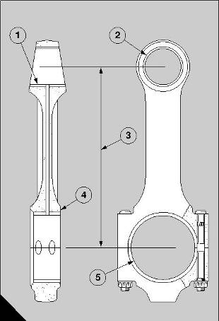
Parallel alignment . . . . . . . . . . . . . . . . . . . . . . . . . . . . . . . . . . . . . . . . . . . . . . . . . . . . . . . 0,025 mm (0.001 in) (Measured between big end and small end, for each 25,40 mm (1.000 in) of test mandrel) Distance between centres . . . . . . . . . . . . . . . . . . . . . . . . . . . . . . . 273,05 to 272,95 mm (10.750 to 10.746 in) |
|
End-float of big end (A4) |
|
End-float. . . . . . . . . . . . . . . . . . . . . . . . . . . . . . . . . . . . . . . . . . . . . . . . . . . 0,20 to 0,40 mm (0.008 to 0.016 in) Permissible worn end-float. . . . . . . . . . . . . . . . . . . . . . . . . . . . . . . . . . . . . . . . . . . . . . . . . 0,558 mm (0.022 in) (End-float of each set of two big ends on common crank pin) |
|
Clearance on diameter of big end (A5) |
|
Clearance. . . . . . . . . . . . . . . . . . . . . . . . . . . . . . . . . . . . . . . . . . . . . . . . 0,026 to 0,086 mm (0.001 to 0.003 in) (Check that crank pin is within limits of ovality) |
|
A |
|
119 |
|
76 |
|
Perkins Engines Company Limited |
|
This document has been printed from SPI². Not for Resale |
![]()
![]()
|
14 |
|
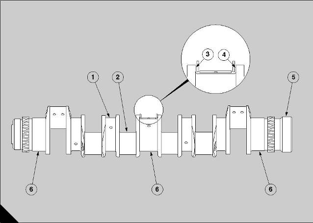
Holes are drilled through the diameter of the main journals. The holes are connected with holes in each crank pin to supply lubricating oil to the big end bearings of the connecting rods. The seventh main journal at the rear of the crankshaft is not drilled. |
|
Crankshaft assembly |
|
14 |
|
For engines built up to build number 970208 the holes are connected through each crankshaft web to the reservoirs in the crank pins (A2). The oil flows to the bearing surfaces of the crank pins from the reservoirs through two holes (A6) which are drilled in each crank pin. |
|
General description |
|
The crankshaft is made from a forging of chromium molybdenum steel. It is nitrided on all surfaces except the tapped holes, the hole for the dowel and the end faces at the front and the rear. The correct balance is obtained when the crankshaft is machined, and there is no requirement for further compensation when assembled. |
|
The small holes in the crankshaft webs are sealed with special blanking plugs (A5). |
|
The crank pin arrangement is 1 and 6, 2 and 5, 3 and 4. Each set of two crank pins is aligned 120 degrees from the other two sets. This gives a firing order of A6, B1, A3, B4, A5, B2, A1, B6, A4, B3, A2 and B5. |
|
The 13 bearing surfaces consist of seven main journals and six crank pins. Each crank pin holds two connecting rods. |
|
A helical gear (A4) with 45 teeth is machined around the rear end of the crankshaft and is the primary drive for the timing gears. The face at the rear of the crankshaft has 16 equally spaced tapped holes to receive the cap screws which retain the flywheel. A dowel of the spring type is fitted in a hole in the face to ensure an accurate alignment of the timing mark on the flywheel. |
|
The crankshafts of engines manufactured up to build number 970209 have an oil reservoir in each crank pin. Access to clean each reservoir is provided by a steel plug (A8) which is retained by a spring clip (A9). The crankshafts of engines from build number 970209 have an arrangement of passages which removes the requirement for oil reservoirs. |
|
A |
|
199 |
|
Perkins Engines Company Limited |
|
77 |
|
This document has been printed from SPI². Not for Resale |
![]()
![]()

|
14 A helical gear (A1) with 45 teeth is machined around Crankshaft pulley, damper and |
|
the front end of the crankshaft. The gear drives the lubricating oil pump through an idler gear. The face at the front end is drilled and tapped for 12 equally spaced bolts, which retain the viscous damper and the multiple groove pulley for the fan drive belts. |
|
alternator pulley |
|
To remove and to fit |
|
14-1 |
|
The main bearings have steel backs with bearing surfaces of lead bronze. The bearing surfaces have a fine top layer of lead indium. |
|
To remove |
|
1 Release the large lock nut on the tensioner of the fan belts and turn the adjustment screw to loosen the fan belts. Remove the fan belts. |
|
The upper half of each bearing has a central groove for oil around the inner surface. A hole is drilled in the centre of the groove and is aligned with a hole in the crankcase which supplies the oil. |
|
2 Remove two horizontally opposite bolts from the crankshaft pulley. Make locally two suitable guide studs and fit them into the bolt holes. |
|
The lower halves of the bearings do not have grooves. |
|
3 Remove the remainder of the twelve bolts from the crankshaft pulley. Lift away the pulley for the fan belts, followed by the damper and then the alternator pulley from the guide studs. |
|
One end of each half bearing has a location tag which is pressed away from one edge. The tags fit in recesses which are machined in the crankcase and in the bearing caps. |
|
Caution: The damper is a heavy component and must not be allowed to fall during removal, because distortion of the casing can prevent its correct operation. |
|
The thrust washers have steel backs with faces of lead bronze. They are made in two halves which are interchangeable. Each half has a location tag at one end. The upper halves are fitted in recesses which are machined in the crankcase on each side of the central main journal; the lower halves are fitted in recesses which are machined in the bearing cap. |
|
To fit |
|
1 Fit the guide studs into the horizontally opposite bolt holes in the end face at the front of the crankshaft. Fit the alternator pulley on the guide studs, followed by the damper and then the pulley for the fan belts. |
|
Lubricating oil is supplied from the central main bearing across the face of each washer, in which grooves are machined to assist the flow of oil. |
|
2 Insert ten bolts, with their spring washers, through the bolt holes and tighten securely the assembly to the crankshaft. Remove the guide studs and fit the two remaining bolts and their spring washers. |
|
3 Tighten each bolt to 80 Nm (59 lbf ft). |
|
78 |
|
Perkins Engines Company Limited |
|
This document has been printed from SPI². Not for Resale |
![]()
![]()
![]()
![]()
|
14 |
|
Front oil seal |
|
To renew |
|
14-2 |
|
Special tools: |
|
Remover/replacer, 21825 905 |
|
To remove |
|
1 Remove the crankshaft pulley, the damper and the alternator pulley, operation 14-1. |
|
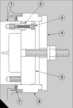
2 Use the kit of the remover/replacer, 21825 905, to remove and to replace the oil seal. Use the two short setscrews in the kit to fit the top plate (A4) to the front end of the crankshaft. Ensure that the counterbores of the holes around the edge of the top plate are away from the engine. |
|
3 Use the centre punch in the kit, through the holes around the edge, to either make three holes in the oil seal, or to mark the centres in order to drill three holes of a size which is suitable to receive the three 40 mm (1.5 in) long self-tapping screws in the kit.’ |
|
Caution: Three holes around the edge of the top plate are marked ’A’ and three holes are marked ’B’. Use the relevant group of holes which align centrally with the metal of the seal. |
|
A |
|
129 |
|
4 Fit the three self-tapping screws through the holes in the top plate into the holes in the seal. Do not overtighten. Remove the setscrews which retain the top plate and fit the three long screws of the kit. Tighten evenly the screws against the end of the crankshaft to pull out the seal. Remove the self- tapping screws when the seal is withdrawn. |
|
Perkins Engines Company Limited |
|
79 |
|
This document has been printed from SPI². Not for Resale |
![]()
![]()
![]()
![]()
![]()

|
14 |
|
To fit |
|
46 |
|
1 Ensure that the crankshaft, the fan adaptor and the oil seal are clean. Use the kit of the remover/replacer, 21825 905, to fit the new oil seal at the front end of the crankshaft. Fit the four special studs (A2) into four equally spaced bolt holes in the end face of the crankshaft (A1). Tighten lightly each special stud and hold the guide (A5) against the end face of the crankshaft. |
|
2 Insert the four cap screws (A3), through the four small holes in the guide, into the special studs. DO NOT tighten the cap screws. |
|
3 Slide the collar (A6) over the guide and the crankshaft to ensure the concentricity of the guide on the crankshaft. Tighten the four cap screws and remove the collar. |
|
4 Before the new oil seal (A7) is fitted, check the guide and the crankshaft for dirt or a rough surface finish which could damage the lip of the oil seal. |
|
5 Apply a small amount of clean engine lubricating oil to the guide and the flange of the crankshaft, remove and discard the yellow inner sleeve, and slide the seal onto the parallel section of the guide. The lip of the seal is toward the crankcase. |
|
6 Slide the collar onto the guide until the face of the |
|
collar presses against the outer face of the oil seal. |
|
A |
|
Caution: This tool is used for both CV8/3008 and CV12/3012 engines and the collar is marked to show the correct assembly for each engine. It is important that the collar is fitted correctly. For CV12/3012 engines, the edge of the shorter of the two shoulders which are machined on the collar must be against the oil seal. |
|
129 |
|
7 Fit the top plate (A4) onto the central stud and engage its shoulder in the collar. Lightly lubricate the thread of the stud and also the thrust washer. Fit the nut and the thrust washer to retain the top plate. Use the correct spanner to tighten the nut until the larger diameter of the collar is in contact with the face of the housing. Remove the complete tool. |
|
8 Fit the crankshaft pulley, the damper and the alternator pulley, operation 14-1. |
|
80 |
|
Perkins Engines Company Limited |
|
This document has been printed from SPI². Not for Resale |
![]()
![]()
|
14 |
|
Rear oil seal |
|
To renew |
|
14-3 |
|
Special tools: |
|
Remover/replacer, 21825 810 |
|
To remove |
|
1 Remove the flywheel, operation 22-1. |
|
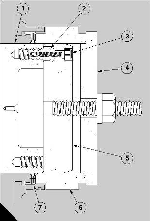
2 Use the kit of the remover/replacer, 21825 810, to remove and to replace the oil seal. Use the two short setscrews in the kit to fit the top plate (A4) to the rear end of the crankshaft. Ensure that the counterbores of the holes around the edge of the top plate are away from the engine. |
|
3 Use the centre punch in the kit, through the holes around the edge, to either make three holes in the oil seal, or to mark the centres in order to drill three holes of a size which is suitable to receive the three self- tapping screws in the kit. |
|
Caution: Three holes around the edge of the top plate are marked ’A’ and three holes are marked ’B’. Use the relevant group of holes which align centrally with the metal of the seal. |
|
A |
|
129 |
|
4 Fit the three self-tapping screws through the holes in the top plate into the holes in the seal. Do not overtighten. |
|
5 Remove the setscrews which retain the top plate and fit the three long screws of the kit. Tighten evenly the screws against the end of the crankshaft to pull out the seal. Remove the self-tapping screws when the seal is withdrawn. |
|
To fit |
|
1 Ensure that the crankshaft, the flywheel housing and the oil seal are clean. Use the kit of the remover/ replacer, 21825 810, to fit the new oil seal at the rear end of the crankshaft as follows: |
|
Perkins Engines Company Limited |
|
81 |
|
This document has been printed from SPI². Not for Resale |
![]()
![]()
![]()
![]()
![]()
|
14 |
|
2 Fit the dowel, which provides the location for the flywheel, into its hole in the end face of the crankshaft and align the guide (A5) for the seal, to ensure that the dowel enters a hole in the guide. The hole is a clearance fit on the dowel. Make a temporary mark on the flange of the crankshaft to show the alignment of the three bolt holes in the guide. |
|
3 Lift away the guide and fit the three special studs (A2) of the kit into the three relevant bolt holes in the end face of the crankshaft (A1). Tighten lightly each special stud, engage correctly the dowel in the hole and hold the guide against the end face of the crankshaft. |
|
4 Insert the three cap screws (A3) of the kit through the guide into the special studs and tighten lightly the cap screws. |
|
5 Before the oil seal (A7) is fitted, check again the guide and the crankshaft for dirt or for a rough surface finish which could damage the lip of the oil seal. |
|
6 Apply a small amount of clean engine lubricating oil to the guide and the flange of the crankshaft, remove and discard the yellow inner sleeve, and fit the seal onto the guide. The lip of the seal is toward the crankcase. |
|
7 Slide the collar (A6) onto the guide until the face of the collar presses against the outer face of the oil seal. |
|
A |
|
129 |
|
Caution: This tool is used for both CV8/3008 and CV12/3012 engines and the collar is marked to show the correct assembly for each engine. It is important that the collar is fitted correctly. For CV12/3012 engines, the edge of the shorter of the two shoulders which are machined on the collar must be against the oil seal. |
|
8 Fit the top plate (A4) onto the central stud and engage its shoulder in the collar. Lightly lubricate the thread of the stud and also the thrust washer. Fit the nut and the thrust washer to retain the top plate. Use the correct spanner to tighten the nut until the larger diameter of the collar is in contact with the face of the housing. Remove the complete tool. |
|
9 Fit the flywheel, operation 22-1. |
|
82 |
|
Perkins Engines Company Limited |
|
This document has been printed from SPI². Not for Resale |
![]()
![]()
|
14 |
|
Crankshaft |
|
To remove and to fit |
|
14-4 |
|
Special tools: |
|
Lift adaptor, crankshaft VP 666 Slide hammer, 21825 849 Remover tool, 21825 858 Guide pin, 21825 843 |
|
To remove |
|
1 Fit the engine in the build stand, operation 16-1. |
|
2 Remove the fan adaptor and the front mountings, operation 21-10. |
|
3 Remove the flywheel and the flywheel housing, operation 22-4. |
|
4 Remove the timing case and the timing gears, operation 15-5. |
|
5 Remove the lubricating oil sump, operation 19-1 or, for new engines, operation 19-5. |
|
6 For early engines, remove the sump adaptor, operation 19-3. |
|
7 Remove the lubricating oil pump, operation 19-7. |
|
8 Turn the crankshaft until one of the pistons of ’A’ bank is at the bottom of its stroke and remove the four nuts of the big end bearing. Withdraw the bearing cap with the bearing. Fit the guide pin, 21825 843, on to one of the bolts of the big end. |
|
9 Push the assembly of the piston and the connecting rod into its bore to the end of its stroke. Push carefully to prevent damage to the top of the piston and the valves. |
|
10 Similarly, repeat the operation for the remainder of the assemblies. Move the guide pin as necessary. |
|
11 Turn the crankcase for access to the big end bearings of ’B’ bank. Repeat the operation for the assemblies of pistons and connecting rods, as for ’A’ bank.Loosen all the bolts that retain the main bearing caps. Release and remove the side bolts. |
|
Perkins Engines Company Limited |
|
83 |
|
This document has been printed from SPI². Not for Resale |
![]()
![]()
![]()
![]()
![]()
|
14 |
|
12 Remove the bolts from each main bearing cap and remove the caps. If necessary use the slide hammer, 21825 849, with the remover tool, 21825 858, to withdraw each main bearing cap (A3,4,5,9) and its lower half bearing (A1,8). When the central main bearing cap (A3) is removed, remove also the lower halves of the thrust washers (A10). |
|
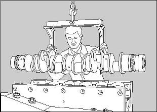
13 Slide the upper halves of the thrust washers (A6) from their recesses around the central main journal. Use the lift adaptor VP 666 to lift the crankshaft from the crankcase and put it on wooden vee blocks. Remove the upper halves of the main bearings (A2,7) from the crankcase and also the upper halves of the thrust washers. |
|
To fit |
|
1 Check for dirt and debris in the passages for the engine lubricating oil of the crankcase, and also of the front and the rear main bearing caps (A5,9). Clean thoroughly the bearing housings and the bearing caps, and also the main journals and the crank pins of the crankshaft. |
|
2 Check also for dirt and debris in the passages of the connecting rods and clean thoroughly the bearing surfaces of the big ends. |
|
3 Ensure that the half bearings and the thrust washers for the main journals of the crankshaft are absolutely clean, and fit the upper half bearings into their housings in the crankcase. Give a full application of clean engine lubricating oil to all of the bearing surfaces. |
|
A |
|
206 |
|
4 Also, apply clean engine lubricating oil to lubricate fully the main journals of the crankshaft. Use the lifting beam VP 666 to lower the crankshaft into the crankcase (B). Ensure that the 16 tapped holes in the end face of the crankshaft are furthest from the build stand, and are at the end of the crankcase to which the timing case is fitted. |
|
5 Apply engine lubricating oil to the upper halves of the thrust washers and insert them into their recesses on each side of the central main bearing. Ensure that the face of lead bronze on each washer is toward the crankshaft web. |
|
B |
|
201 |
|
84 |
|
Perkins Engines Company Limited |
|
This document has been printed from SPI². Not for Resale |
![]()
![]()
|
14 |
|
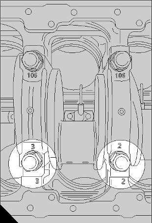
6 Fit the lower halves of the main bearings into the bearing caps and give a full application of clean engine lubricating oil to all of the bearing surfaces. Fit all the assemblies of the bearing caps except the bearing cap for the central main bearing. Ensure that the numbers which are stamped on each bearing cap, to give its relationship, match the numbers which are stamped on the crankcase, as shown (A). |
|
7 Apply a minimum amount of grease to the recesses at the sides of the bearing cap for the central main bearing and insert the lower halves of the thrust washers into the recesses. Ensure that the face of lead bronze on each washer is away from the bearing cap. |
|
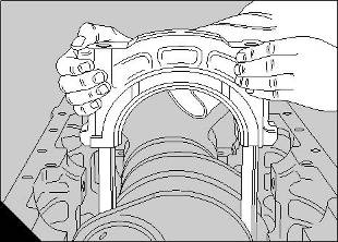
8 Fit carefully the assembly of the bearing cap for the central main bearing. Ensure that the halves of the thrust washers remain in their positions during the operation. |
|
9 Apply engine lubricating oil to the threads, and under the heads, of the main bolts which retain the main bearing caps. Fit carefully each bolt into its location. Do NOT allow the bolts to fall into the holes because the threads could be damaged. Insert fully each main bolt by hand only. |
|
Caution: On new engines, the bolts fitted to the front, centre and rear bearing caps, are different and are fitted with hardened washers. Ensure that the special washers are fitted to the bolts before the bolts are fitted to the engine. Do NOT fit any other type of washer. |
|
A |
|
203 |
|
Caution: If a new front, centre or rear bearing cap is fitted, do NOT fit the old type of bolts. The new bolts and special washers MUST be used. |
|
10 Apply engine lubricating oil to the threads, and under the heads, of the side bolts which hold rigidly the main bearing caps. Fit the plain washers on the M16 bolts and the ’Dowty’ sealing washers on the M14 bolts. Insert fully each bolt, by hand, through the side walls of the crankcase. |
|
11 Check that the faces which are machined on the front and the rear of each main bearing cap are aligned with the faces in the crankcase. Tighten lightly all of the main bolts and then all of the side bolts. |
|
B |
|
202 |
|
12 Tighten, in the sequence shown in page 86/B, all the main bolts of the bearing caps by increments of 50 Nm (37 lbf ft) until the maximum torque of 177 Nm (130 lbf ft) is applied. At the end of this phase of the operation, the main bolts of the main bearing caps at the front, at the centre and at the rear are tightened fully. |
|
Caution: Check frequently that the crankshaft can rotate freely while the bolts are tightened. |
|
Perkins Engines Company Limited |
|
85 |
|
This document has been printed from SPI². Not for Resale |
![]()
![]()
|
14 13 Continue to tighten the bolts - numbers 5 to 12 (B) - for the remainder of the main bearing caps, until the maximum torque of 488 Nm (360 lbf ft) is applied. |
|
14 Tighten all the side bolts, in alphabetical sequence, until a maximum torque of 114 Nm (85 lbf ft) is applied. At the end of this phase of the operation, the side bolts of the front, central and rear main bearings are tightened fully. |
|
15 Continue to tighten the remainder of the side bolts - letters C to J (B) - in alphabetical sequence, until a maximum torque of 177 Nm (130 lbf ft) is applied. |
|
16 Put a dial test indicator with a magnetic base on the end face of the crankcase. Set the button of the dial test indicator on the end of the crankshaft (A). Use a lever to move the crankshaft backward and forward against the thrust washers and check the readings on the dial test indicator. Permissible end- float is 0,10 to 0,30 mm (0.004 to 0.012 in). |
|
Turn the crankcase in the build stand so that the ’A’ bank cylinders are horizontal. Fit each of the connecting rods, of the ’A’ bank cylinders, to their respective crank pins, operation 13-3. |
|
A |
|
205 |
|
A |
|
192 |
|
86 |
|
Perkins Engines Company Limited |
|
This document has been printed from SPI². Not for Resale |
![]()
![]()
|
14 |
|
17 When all of the ’A’ bank connecting rods have been fitted, turn the build stand until the ’B’ bank cylinders are horizontal and use the same procedure to fit the connecting rods of the ’B’ bank. |
|
18 Set a dial test indicator as shown (page 67/B) and check the end float of each big end. The permissible end float is 0,2 to 0,4 mm (0.008 to 0.016 in). |
|
19 Ensure that the crankshaft turns freely. 20 Fit the lubricating oil pump, operation 19-7. |
|
21 For early engines, fit the sump adaptor, operation 19-3. |
|
22 Fit the lubricating oil sump, operation 19-1 or, for new engines, operation 19-5. |
|
23 Fit the timing case and the timing gears, operation 15-5. |
|
24 Fit the flywheel and the flywheel housing, operation 22-4. |
|
25 Fit the fan adaptor, operation 21-10. |
|
26 Remove the engine from the build stand, operation 16-1. |
|
Perkins Engines Company Limited |
|
87 |
|
This document has been printed from SPI². Not for Resale |
![]()
![]()
|
14 To dismantle and to assemble |
|
14-5 |
|
Special tools: |
|
Lift adaptor, crankshaft VP 666 Remover/replacer, 27610005 |
|
To dismantle |
|
1 Press down each plug (A1) of the reservoirs and release the circlips. Fit the remover/replacer, 27610005 (A2), on the spigot of the plug and withdraw the plug. Early engines are fitted with a different type of plug which has a threaded hole, for these engines use remove/replacer, 21825 859, together with the slide hammer, 21825 849. Clean all the components with a degreasing solution. |
|
A |
|
01 |
|
4 Check for damage on the front and rear faces at the ends of the crankshaft. Also check for small marks on the circumferences which are the location faces for the flywheel and the pulley. |
|
To assemble |
|
5 If the crankshaft is usable, small marks can be removed from the journals, the crank pins, the thrust faces and the locations on the ends by the use of a very fine grade of oil stone. |
|
1 Fit new ’O’ ring seals to the blanking plugs of the reservoirs. In sequence, apply a small amount of ’Stantyte’ lubricant or ’Morris’s liner lubricant’ around the complete circumference of each housing in the crankshaft. Press fully each plug into its housing and fit the circlip into its recess in the housing. Use the relevant remover/replacer to pull backward the plug against the circlip. |
|
Main bearings and thrust washers |
|
To inspect 14-6 |
|
14-7 |
|
To clean and inspect |
|
1 Remove the crankshaft, operation 14-4. |
|
To clean |
|
2 Check for wear, cracks and contamination in the surfaces of the bearings. Renew bearings as a set if it is possible that a bearing will not complete a further full period of service. |
|
1 Wash thoroughly the oil holes and reservoirs of the crankshaft with kerosene and dry with compressed air. Ensure that all surfaces of the crankshaft are cleaned thoroughly. |
|
3 Check the thickness of the thrust washers. |
|
Nominal dimensions for new thrust washers are: |
|
To inspect |
|
2,93 to 3,0 mm (0.116 to 0.118 inch) |
|
1 Hold the shaft in suitable wooden blocks under main journals nos. 1 and 7. Check for cracks in the crankshaft, by the electro-magnetic method if possible. |
|
New thrust washers must be fitted if there is wear on the thrust faces and also if the crankshaft has excessive end-float. |
|
2 Check for damage and small marks on the main journals, crank pins and thrust faces; check for ovality the journals and crank pins. Refer to Perkins Engines Company Limited, Shrewsbury, for the instructions S.R.S. 121 Issue 2 for the repair of worn or damaged journals and crank pins. |
|
3 Hold the crankshaft in ’V’ blocks under the main journals nos. 1 and 7 and check the amount of deflection at the central main journal. The permissible amount of the deflection, which is given on page 89, must be gradual along the length of the crankshaft. |
|
88 |
|
Perkins Engines Company Limited |
|
This document has been printed from SPI². Not for Resale |
![]()
![]()
![]()
![]()
![]()
![]()
![]()
![]()
|
14 Width of central bearing (A4) across thrust washers |
|
Fits and clearances |
|
81,15 to 81,30 mm (3.1949 to 3.2008 in) |
|
Crankshaft journals |
|
Clearance (new)0,13 to 0,33 mm (0.005 to 0.013 in) Permissible worn clearance0,483 mm (0.019 in) |
|
Diameter (A1)145,975 to 146,000 mm (5.7470 to 5.7480 in) |
|
Flywheel on crankshaft |
|
Permissible worn dimensions145,910 mm (5.7445 in) Ovality - permissible worn dimensions0,076 mm (0.0030 in) Journals in main bearings – clearance0,076 to 0,145 mm (0.0030 to 0.0057 in) |
|
Bore of flywheel160,000 to 160,025 mm (6.2992 to 6.3002 in) Diameter of crankshaft (A5)159,961 to 159,986 mm (6.2976 to 6.2986 in) |
|
Clearance (new)0,014 to 0,064 (0.0006 to 0.0026) |
|
Crank pins |
|
Diameter (A2)97,978 to 98,000 mm (3.8574 to 3.8583 in) Diameter - permissible worn dimensions97,914 mm (3.8548 in) Ovality - permissible worn dimensions0,076 mm (0.0030 in) |
|
Deflection of crankshaft |
|
Deflection of crankshaft (A6) when it is held in 'V' blocks under nos. 1 and 7 main journals0,1000 mm (0.0039 in) (Deflection must be gradual from outer main journals to central main journal) |
|
End float of crankshaft |
|
Width between crankshaft webs of central journal (A3)81,43 to 81,48 mm (3.2059 to 3.2079 in) |
|
A |
|
131 |
|
Perkins Engines Company Limited |
|
89 |
|
This document has been printed from SPI². Not for Resale |
![]()
![]()
|
14 |
|
90 |
|
Perkins Engines Company Limited |
|
This document has been printed from SPI². Not for Resale |
![]()
![]()
|
15 |
|
Timing gears and timing case |
|
15 |
|
General description |
|
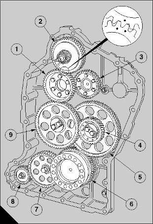
The timing gears (A) of the engine are protected by a housing at the rear of the engine which has two components, the timing case and the flywheel housing. |
|
The timing case is made from heavy-duty cast iron and is bolted to the rear end of the crankcase. It has mountings for the connection block for the spill fuel, the starter motor and the coolant pump. It holds the inner bearing, and the housing for the oil seal, of the auxiliary drive shaft. |
|
For early engines, the oil seal of the auxiliary drive shaft is separate and is pressed into its housing. The current engine has a housing with an integral oil seal. The housing also has an ’O’ ring in a groove around its spigot to seal the bore in the timing case. |
|
The flywheel housing is also made from heavy-duty cast iron and is bolted to the timing case. It holds the outer bearing for the end of the auxiliary drive shaft and has a mounting for the fuel lift pump. The correct location of the assembly is ensured by a large dowel and the axles of the idler gears in the timing case. |
|
The arrangement of the timing gears consists of the drive gear on the crankshaft (A6), the idler gear (A7) for the drive to the gear of the coolant pump (A8), the double idler gear (A4,5), the main idler gear (A9), the drive gear for the fuel injection pump/camshafts (A1), the two camshaft gears (A3) and the auxiliary drive gear (A2). The drive gear for the fuel injection pump/ camshafts is bolted to the outer face of the camshaft gear of ’B’ bank. |
|
A |
|
132 |
|
The axles of the idler gears are bolted to the rear end of the crankcase and the end float of each gear is limited by the thrust washers. |
|
There are timing marks on the drive gear of the crankshaft, the double idler gear, the main idler gear, the drive gear for the fuel injection pump/camshafts, the two camshaft gears and the auxiliary drive gear. The use of the timing marks ensures that the mesh of each gear is correct, before the timing of the fuel injection pump is checked and before the tappet clearances are set. The teeth of the timing gears are engaged correctly when the mark on the side of the tooth of a gear is between the marks on the sides of two teeth of another gear (A). |
|
Perkins Engines Company Limited |
|
91 |
|
This document has been printed from SPI². Not for Resale |
![]()
![]()