 English
 Espaol
 Franais
 阿拉伯
阿拉伯 中文
中文 Deutsch
 Italiano
 Português
 日本
日本 韩国
韩国 български
 hrvatski
 esky
esky Dansk
Dansk Nederlands
 suomi
suomi Ελληνικ
 印度
印度 norsk
norsk Polski
 Roman
Roman русский
 Svenska
Perkins珀金斯2806C-E18发动机维修检测技术供应商,Perkins珀金斯2806C-E18发动机维修检测技术技术价格规格咨询服务,Perkins珀金斯2806C-E18发动机维修检测技术零配件供应,Perkins珀金斯2806C-E18发动机维修检测技术售后服务中心,Perkins珀金斯2806C-E18发动机维修检测技术,Perkins珀金斯2806C-E18发动机维修检测技术详细的技术参数,

产品中心
Perkins珀金斯2806C-E18发动机维修检测技术
详细描述
|
Perkins 2800 Series |
|
Mode ls 2806C-E16 and 2806C-E18 |
|
DIAGNOSTIC MANUAL |
|
6 cylinder turbocharged diesel engine |
|
Publica tion TS D 3453E, Is sue 3. © Proprie tary informa tion of P erkins Engine s Compa ny Limited, a ll rights reserved. The informa tion is corre ct a t the time of print. Publishe d in J une 2004 by Te chnica l Publica tions , Perkins Engine s Compa ny Limited, Tixa ll Road, S tafford, S T16 3UB, Engla nd |
|
Diagnos tic Manua l, TSD 3453E, Is sue 3 |
|
i |
|
This document has been printed from SPI². Not for Resale |
![]()
![]()
|
To remove |
|
Warning! The electrical circuit for the fuel injector units operates on 110 volts. Do NOT work on the fuel injector units unless the power supply to the ECM has been disconnected. |
|
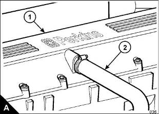
1 Disconnect the wiring harness at the socket on the rocker cover (A1). 2 Disconnect and remove the engine breather pipe (A2). |
|
3 Loosen fully the bolts which retain the rocker cover, but do not remove the bolts from the assembly; allow them to be retained by the seal. |
|
4 Remove the rocker cover. |
|
To fit |
|
1 Inspect the seal of the rocker cover and renew if worn of damaged. |
|
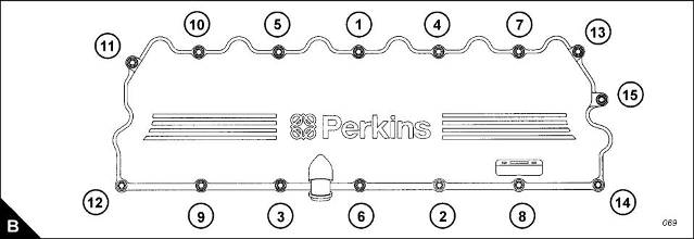
2 Fit the rocker cover, complete with seal and bolts. Tighten the bolts to a torque of 20 Nm (15 lbf ft); use the sequence shown (B). |
|
3 Fit the engine breather pipe (A2). |
|
4 Connect the wiring harness. Ensure that the wiring harness is fully engaged with the connector. |
|
28 |
|
Workshop Manual, TSD3450E, Issue 2 |
|
This document has been printed from SPI². Not for Resale |
![]()
![]()
![]()
![]()
|
3 |
|
2800 |
|
Rocker lever and rocker shaft assemblies |
|
To remove and to fit |
|
Operation 3-2 |
|
To remove |
|
1 Remove the rocker cover, Operation 3-1. |
|
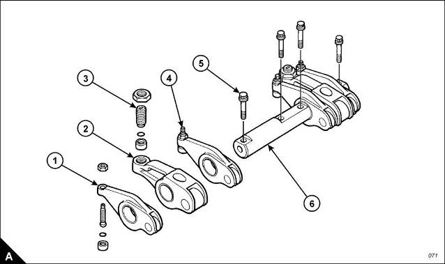
2 The valve rocker levers (A1) and the unit injector rocker levers (A2) can move on the shaft (A6) after the four bolts (A5) have been removed. The shaft (A6) should be kept level when removed from the cylinder head. To avoid possible personal injury, keep fingers clear of the rocker levers (A1 and A2) during removal of the assembly from the cylinder head. |
|
3 Remove the four bolts (A5). |
|
4 Remove the shaft (A6), valve rocker levers (A1) and unit injector rocker levers (A2) as a unit. 5 Repeat steps 1 and 2 for the rocker shaft assemblies which remain. |
|
To fit |
|
1 Loosen the adjustment screws (A3 and A4) of each of the rocker levers which have been removed. Install the rocker shaft assembly in the reverse order to removal. |
|
2 Set the tappet clearances, Operation 3-4. 3 Check/adjust the unit injectors, Operation 3-13. 4 Fit the rocker cover, Operation 3-1. |
|
Workshop Manual, TSD3450E, Issue 2 |
|
29 |
|
This document has been printed from SPI². Not for Resale |
![]()
![]()
![]()
![]()
|
3 |
|
2800 |
|
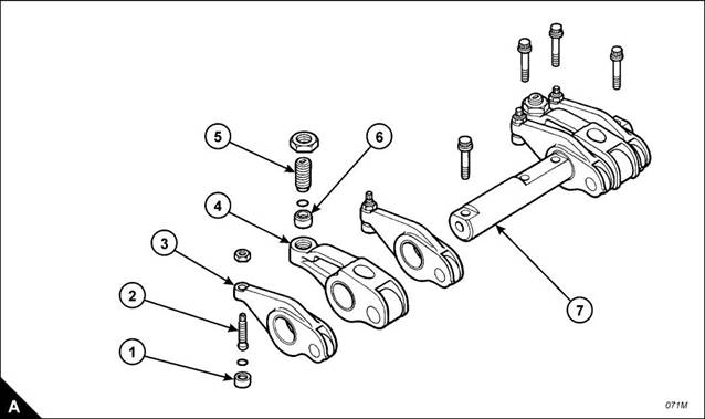
To dismantle and to assemble |
|
Operation 3-3 |
|
To dismantle |
|
Note: Check the condition of all components and renew any which are worn or damaged. |
|
1 Slide the valve rocker levers (A3) and the unit injector rocker levers (A4) from the shaft (A7). |
|
Note: Fit a new ‘O’ ring seal to any rocker lever adjuster if its button (A1) has been removed from the adjustment screw (A2). |
|
2 Remove the button (A1) from the adjustment screw (A2) in the valve rocker lever (A3). 3 Remove the button (A6) from the adjustment screw (A5) in the unit injector rocker lever (A4). 4 Repeat steps 1 to 3 for the rocker lever assemblies which remain. |
|
30 |
|
Workshop Manual, TSD3450E, Issue 2 |
|
This document has been printed from SPI². Not for Resale |
![]()
![]()
![]()
![]()
|
3 |
|
2800 |
|
To assemble |
|
1 Install new ‘O’ ring seals in the buttons (A1). |
|
2 Install new ‘O’ ring seals in the buttons (A6). |
|
3 To fit the ‘O’ ring seals and buttons to the valve rocker levers, proceed as follows: a. Support the valve rocker lever (A3) in a vice which has soft jaws. |
|
b. Put the ‘O’ ring seal and button (A1) on the round end of the adjustment screw (A2). c. Use a soft hammer to seat the button on the adjustment screw. |
|
4 To fit the ‘O’ ring seals and buttons to the unit injector rocker levers, proceed as follows: a. Support the unit injector rocker lever (A4) in a vice which has soft jaws. |
|
b. Put the ‘O’ ring seal and button (A6) over the end of adjustment screw (A5). c. Use a soft hammer to seat the button on the adjustment screw. |
|
5 Repeat steps 3 and 4 for the rocker levers which remain. |
|
6 Fit the assembled rocker levers to the shafts (A7). Ensure that they are fitted to their original positions. |
|
Workshop Manual, TSD3450E, Issue 2 |
|
31 |
|
This document has been printed from SPI². Not for Resale |
![]()
![]()

|
3 |
|
2800 |
|
How to check/adjust the tappet clearances |
|
Operation 3-4 |
|
Special requirements Special tools |
|
Tappet clearances |
|
Description |
|
Part number |
|
Inlet |
|
Exhaust |
|
Engine turning tool |
|
CH11148 |
|
0,38 mm (0.015 in) |
|
0,76 mm (0.030 in) |
|
The tappet clearance is measured between the rocker levers and the top of the valve bridge pieces. The operation must be done with the engine cold and stopped. Refer also to Operation 3-13, How to check/adjust the electronic unit injectors. |
|
1 Remove the rocker cover, Operation 3-1. |
|
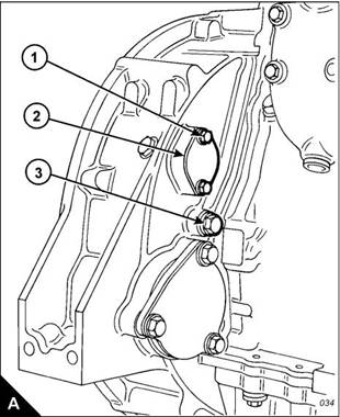
2 Remove the cover (A2) from the flywheel housing. The top bolt (A1) is the timing bolt. |
|
Caution: If a customer-fitted speed sensor is fitted to the flywheel housing, it must be removed before the engine turning tool can be inserted. |
|
3 Remove the plug (A3) from the timing bolt location in the flywheel housing and fit the timing bolt. |
|
Note: There are two locations for the timing bolt, one at each side of the flywheel housing. Use the location that is the most convenient. |
|
4 Insert the engine turning tool, CH11148, into the flywheel housing through the aperture behind the cover |
|
1 |
|
(A2). Use a / inch drive ratchet with the turning tool to rotate the engine flywheel in the normal direction of |
|
2 |
|
rotation (anti-clockwise when viewed on the flywheel) until the timing bolt engages with the threaded hole in the flywheel. The piston of number 1 cylinder is now at TDC (top dead centre). |
|
Caution: If the flywheel is turned past the threaded hole, the flywheel must be turned in the opposite direction for approximately 45 degrees and then back in the normal direction of rotation until the timing bolt engages with the threaded hole. This is to eliminate backlash. |
|
Continued |
|
32 |
|
Workshop Manual, TSD3450E, Issue 2 |
|
This document has been printed from SPI². Not for Resale |
![]()
![]()
![]()
![]()

|
3 |
|
2800 |
|
5 Check the inlet and exhaust valves of the number 1 cylinder. If they are fully closed the piston is on its compression stroke and the rocker levers can be moved by hand. If the rocker levers can not be moved because the valves are slightly open, the piston is on its exhaust stroke. If it is on its exhaust stroke, withdraw the timing bolt and turn the flywheel a further 360 degrees in the normal direction of rotation so that the number 1 cylinder is set to TDC on its compression stroke, then insert again the timing bolt. |
|
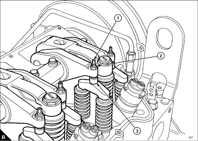
6 Before each set of tappet clearances is adjusted, ensure that the roller of the rocker lever is fully against the camshaft lobe. |
|
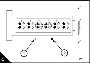
7 Use a set of feeler gauges, inserted at the position shown (B3) between the valve bridge piece and the rocker lever button, to check the tappet clearances for the inlet valves (C1) on cylinders 1, 2 and 4. Adjust the clearances if necessary. Check the tappet clearance for the exhaust valves (C2) on cylinders 1, 3 and 5, and adjust the clearances if necessary. |
|
Continued |
|
Workshop Manual, TSD3450E, Issue 2 |
|
33 |
|
This document has been printed from SPI². Not for Resale |
![]()
![]()
|
3 |
|
2800 |
|
Notes: |
|
l Move each valve bridge piece before the feeler gauge is inserted to reduce the effect of the oil film. l During the procedure, ensure that the feeler gauge is fully inserted |
|
8 After each unit has been adjusted, tighten the lock nut (B2) of the adjustment screw (B1) to a torque of 30 +/ - 4 Nm (22 +/- 3 lbf ft). |
|
9 Withdraw the timing bolt and rotate the flywheel by 360 degrees so that the number 6 piston is at TDC on its compression stroke. Insert again the timing bolt into the threaded hole. |
|
10 Check the tappet clearances for the inlet valves (C1) on cylinders 3, 5 and 6. Adjust the clearances if necessary. Check the tappet clearances for the exhaust valves (C2) on cylinders 2, 4 and 6, and adjust the clearances if necessary. |
|
11 After each unit has been adjusted, tighten the lock nut of the adjustment screw to a torque of 30 +/- 4 Nm (22 +/- 3 lbf ft). |
|
12 Check again the tappet clearances for all six cylinders. |
|
13 Fit the rocker cover. Remove the engine turning tool and the timing bolt and fit the cover to the flywheel housing. Fit the plug to the timing bolt location. |
|
34 |
|
Workshop Manual, TSD3450E, Issue 2 |
|
This document has been printed from SPI². Not for Resale |
![]()
![]()
![]()
|
3 |
|
2800 |
|
Cylinder head assembly |
|
To remove and to fit |
|
Operation 3-5 |
|
Special requirements |
|
Special tools Description |
|
Consumable products |
|
Part number GE50019 GE50020 VP12712 |
|
Description |
|
Part number |
|
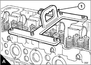
Guide bolt, camshaft gear Socket, cylinder head bolt Lifting bracket |
|
Special lubricant |
|
CV60895 |
|
Retaining compound |
|
21820 638 |
|
To remove |
|
1 Remove the thermostat housing, Operation 12-10. 2 Remove the exhaust manifold, Operation 9-1. |
|
3 Remove the rocker lever and rocker shaft assemblies, Operation 3-2. 4 Remove the electronic unit injectors, Operation 3-12. |
|
5 Remove the gear case cover, Operation 6-1. |
|
6 Disconnect the cable and remove the timing sensor from the cylinder head. 7 Remove the support bracket which is fitted between the gear case and the cylinder head. |
|
8 Remove one bolt from the camshaft gear and install the guide stud, GE50019. Remove the five bolts which remain and withdraw carefully the camshaft gear. Remove the guide stud. |
|
9 Disconnect the fuel lines from the front and rear of the cylinder head. Fit temporary covers to the fuel lines and also to the ports on the cylinder head. |
|
10 Remove the cylinder head bolts; use the special socket, GE50020. |
|
11 Fit the lifting bracket (A1), VP12712, to the cylinder head and attach a suitable hoist. Remove the cylinder head. The cylinder head weighs approximately 148 kg (325 lb). |
|
Continued |
|
Workshop Manual, TSD3450E, Issue 2 |
|
35 |
|
This document has been printed from SPI². Not for Resale |
![]()
![]()
![]()
![]()

|
3 |
|
2800 |
|
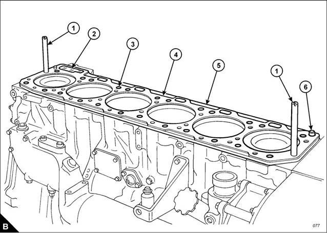
12 Remove the cylinder head gasket (B4). |
|
13 Remove the ‘O’ ring seal from the oil transfer tube (B6) and remove the 24 coolant seals (B3). 14 Remove the seal (B2). |
|
15 Remove the spacer plate (B5) and discard the spacer plate gasket. 16 Remove the second ‘O’ ring seal from the oil transfer tube (B6). |
|
36 |
|
Workshop Manual, TSD3450E, Issue 2 |
|
This document has been printed from SPI². Not for Resale |
![]()
![]()
|
3 |
|
2800 |
|
To fit |
|
1 If the oil transfer tube (B6) has been removed, apply retaining compound, 21820 638, and insert it in the crankcase. It must protrude from the top face of the crankcase by 20,0 +/- 0,5 mm , (0.79 +/- 0.02 in). Remove any excess compound and ensure that the bore of the oil transfer tube is clean. |
|
2 If the rear dowel has been removed, apply retaining compound, 21820 638, and insert it in the crankcase. It must protrude from the top face of the crankcase by 18,5 +/- 0,5 mm (0.73 +/- 0.02 in). |
|
3 If the front dowel, close to the oil transfer tube, has been removed, it must be fitted in a dry condition. It must protrude from the top face of the crankcase by 16,0 +/- 0,5 mm (0.63 +/- 0.02 in). |
|
Note: Ensure that the spacer plate and the machined surface of the cylinder block are clean and free from dirt and gasket material. Both surfaces of the spacer plate gasket and the top of the cylinder block must be clean. Do NOT use a gasket adhesive on the surfaces. |
|
4 Fit suitable guide studs (B1) to the cylinder block. Fit a new spacer plate gasket over the dowels in the cylinder block. |
|
Note: Apply a small amount of clean engine oil to the seals and ‘O’ ring seals before installation. 5 Fit a new ‘O’ ring seal to the oil transfer tube (B6). |
|
6 Fit the spacer plate (B5) and fit the second ‘O’ ring seal to the oil transfer tube (B6). Fit the 24 coolant seals (B3) and a new seal (B2) to the oil drain passage. |
|
7 Check, and if necessary adjust, the protrusion of the cylinder liners, Operation 7-3. 8 Fit a new cylinder head gasket (B4) to the spacer plate. |
|
Continued |
|
Workshop Manual, TSD3450E, Issue 2 |
|
37 |
|
This document has been printed from SPI². Not for Resale |
![]()
![]()
|
3 |
|
2800 |
|
9 Fasten a hoist to the cylinder head, use the lifting bracket VP12712, and lower the cylinder head onto the spacer plate. |
|
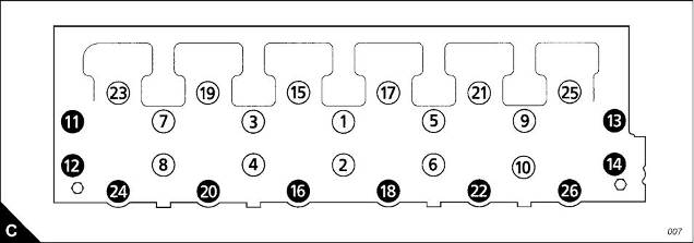
10 Apply special lubricant, CV60895, to the washers, the threads and under the heads of the bolts and fit the cylinder head bolts and washers. The long bolts must be fitted at the positions shown in the black circles (C). Use the special socket, GE50020, and the procedure which follows to tighten the bolts correctly: |
|
a. Tighten the cylinder head bolts in the sequence given (C) to a torque of 270 +/- 15 Nm (200 +/- 11 lbf ft). b. Tighten the cylinder head bolts in the sequence given (C) to a torque of 450 +/- 20 Nm (333 +/- 15 lbf ft). |
|
c. Again, tighten the cylinder head bolts in the sequence given (C) to a torque of 450 +/- 20 Nm (333 +/- 15 lbf ft). |
|
Caution: After the cylinder head assembly has been removed and fitted, it is necessary to check the backlash between the camshaft and the idler gears. Incorrect adjustment can cause damage to components. |
|
11 Fit the camshaft gear. Check and, if necessary, adjust the backlash between the camshaft gear and the idler gear, Operation 3-11. |
|
12 Fit the gear case cover, Operation 6-1. |
|
13 Fit the support bracket between the cylinder head and the gear case. 14 Fit the electronic unit injectors, Operation 3-12. 15 Fit the rocker lever and shaft assemblies, Operation 3-2. 16 Fit the exhaust manifold, Operation 9-1. |
|
17 Fit the thermostat housing, Operation 12-10. |
|
18 Remove the covers from the fuel lines and from the fuel line ports on the cylinder head. Connect the fuel lines to the cylinder head and attach any relevant clamps. |
|
19 Fit the timing sensor and connect the cable. |
|
38 |
|
Workshop Manual, TSD3450E, Issue 2 |
|
This document has been printed from SPI². Not for Resale |
![]()
![]()
|
3 |
|
2800 |
|
Valve springs |
|
To remove and to fit |
|
Operation 3-6 |
|
Special requirements |
|
Special tools |
|
Description |
|
Part number |
|
Valve spring compressor |
|
GE50026 |
|
To remove |
|
Note: The valve springs can be removed with the cylinder head either fitted to or removed from the engine. The procedure given here is for use when the cylinder head is fitted to the engine. Before any components are removed, ensure that the relevant piston is set to the top of its compression stroke. If the piston is not at this position, the valves can fall into the cylinder liner. |
|
Caution: If a valve falls into the cylinder liner, the cylinder head must be removed. |
|
1 Remove the rocker lever and rocker shaft assemblies, Operation 3-2. 2 Remove the electronic unit injectors, Operation 3-12. |
|
3 Set the piston for the relevant valve spring assembly to the top of its compression stroke. |
|
4 Use the hold-down clamp from the electronic unit injector to secure the valve spring compressor, GE50026, to the cylinder head. |
|
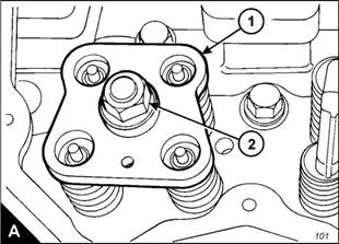
5 Insert the stud and base of the valve spring compressor into the bore of the injector sleeve. Use the bolt and clamp from the electronic unit injector to secure the stud and base to the cylinder head. Fit the compressor plate (A1) over the stud and fit the thrust bearing, the washer and the nut (A2) |
|
6 Tighten the nut until the collets are loose on the valves. |
|
7 Remove two collets from each valve. |
|
8 Loosen slowly, then remove the nut, washer, thrust bearing and plate. 9 Remove the rotocoils, valve springs and washers from each valve. 10 Inspect the valve springs, refer to Chapter 2, Specifications for the correct dimensions and spring force. 11 Repeat steps 3 to 10 for the other valve spring assemblies which are to be removed. |
|
Workshop Manual, TSD3450E, Issue 2 |
|
39 |
|
This document has been printed from SPI². Not for Resale |
![]()
![]()
![]()
![]()


|
3 |
|
2800 |
|
To fit |
|
1 Apply clean engine oil to the relevant valve stems. |
|
2 Fit the washer, valve spring and rotocoil to each valve. |
|
3 Use the valve spring compressor, GE50026, to compress the valve springs. Note: The collets are tapered. When fitted, the large (thick) diameter must be uppermost. |
|
4 Fit two collets to each valve. |
|
Caution: The collets can be dislodged from the valve stem during the removal of the valve spring compressor. Ensure that the collets are seated correctly during this procedure. |
|
5 Loosen slowly and then remove the nut (A2) and plate (A1) of the valve spring compressor. Remove the other parts of the valve spring compressor tool and ensure that the collets are fitted correctly to the valve stems. |
|
6 Tap lightly each valve with a soft hammer to ensure that the collets are seated correctly. 7 Fit the electronic unit injectors, Operation 3-12. |
|
8 Fit the rocker lever and rocker shaft assemblies, Operation 3-2. |
|
40 |
|
Workshop Manual, TSD3450E, Issue 2 |
|
This document has been printed from SPI². Not for Resale |
![]()
![]()
|
3 |
|
2800 |
|
Valves |
|
To remove and to fit |
|
Operation 3-7 |
|
Special requirements |
|
Special tools |
|
Description |
|
Part number |
|
Valve spring compressor |
|
GE50026 |
|
To remove |
|
1 Remove the cylinder head, Operation 3-5. |
|
Note: If more than one valve is to be removed, make a note of the position of the valves as they are removed from the cylinder head. |
|
2 Put the cylinder head, flame face down, on a bench with a soft surface and release the valves by use of the valve spring compressor, GE50026. Use the procedure given in Operation 3-6. |
|
3 Withdraw the valves from the cylinder head. |
|
4 Repeat the procedure for all valves which are to be removed. |
|
To fit |
|
1 Apply clean engine oil to the stems of the valves. Fit the valves to their original positions in the cylinder head. 2 Use the special tool, GE50026, and the procedure given in Operation 3-6, to install the valve springs. 3 Fit the cylinder head, Operation 3-5. |