 English
 Espaol
 Franais
 阿拉伯
阿拉伯 中文
中文 Deutsch
 Italiano
 Português
 日本
日本 韩国
韩国 български
 hrvatski
 esky
esky Dansk
Dansk Nederlands
 suomi
suomi Ελληνικ
 印度
印度 norsk
norsk Polski
 Roman
Roman русский
 Svenska
产品中心
John Deere柴油机难启动的原因为曲轴位置/凸轮位置传感器不同步的维修技术资料约翰迪尔机油冷却器RE59296
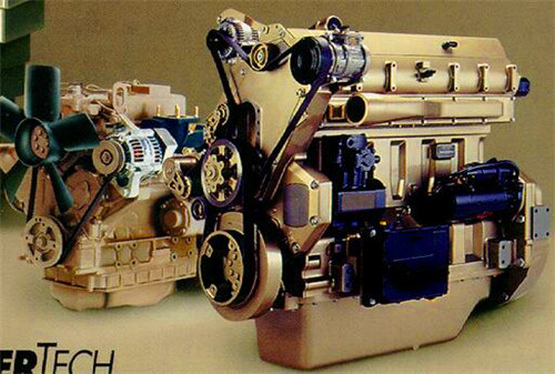
John Deere柴油机难启动的原因为曲轴位置/凸轮位置传感器不同步的维修技术资料约翰迪尔机油冷却器RE59296
重要事项:不要将探头强行插入接头计算正确的喷射开始时间和喷射量
否则会导致端子损坏。使用燃油喷射,然后命令EUIs
JT07328连接器适配器测试套件。测量约翰迪尔位置传感器信号的凸轮和曲轴位置传感器接头之间的已知关系。这将确保信号允许约翰迪尔ECU识别何时一个信号端子没有损坏。与另一个不同步。
如果出现以下情况,将设置DTC SPN 637 FMI 7:
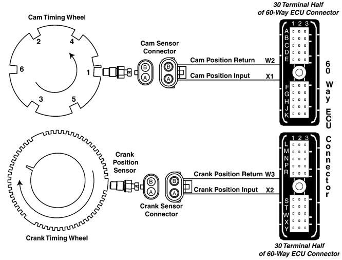
约翰迪尔凸轮轴和曲轴位置传感器
•ECU检测到凸轮和曲柄输入
•约翰迪尔凸轮和曲柄位置传感器均不同步。感应式拾波传感器,用于检测
凸轮和曲柄正时轮。如果设置了DTC SPN 637 FMI 7,ECU将使用
确定发动机转速和发生的曲柄位置输入:
相对于TDC的精确活塞位置。使用
凸轮位置输入,ECU能够确定•根据故障代码的原因,气缸在压缩发动机末端时可能会死亡,然后可能会重新启动,也可能不会重新启动。(打、击等的)一下根据此信息,ECU
IMPORTANT: Do not force probes into connector calculates the correct start of injection and amount
terminals or damage will result. Use of fuel to inject, then commands the EUIs
JT07328 Connector Adapter Test Kit accordingly. A known relationship between the cam to make measurements in position sensor signal and the crank position sensor connectors. This will ensure that signal allows the ECU to recognize when one signal terminal damage does not occur. is not in sync with the other.
DTC SPN 637 FMI 7 will set if:
Camshaft and Crankshaft Position Sensors
• The ECU detects that the cam and crank inputs are
• The cam and crank position sensors are both not in sync with each other. inductive type pickup sensors that detect notches on
the cam and crank timing wheels. The ECU uses the If DTC SPN 637 FMI 7 sets, the following will
crank position input to determine engine speed and occur:
precise piston position in relation to TDC. Using the
cam position input, the ECU is able to determine • Depending on the cause of the trouble code, the when a cylinder is at the end of the compression engine may die, and then it may or may not restart. stroke. Based on this information, the ECU
Level 6 ECU - DTC SPN 637 FMI 7 Crank Position/Cam Position Out of Sync Diagnostic Procedure
NOTE: Before using this diagnostic procedure, perform a preliminary inspection of the 60-way ECU connector and the cam and crank position sensors connectors looking for dirty, damaged, or poorly positioned terminals.
|
1 Intermittent Fault Test |
NOTE: For wiring and theory of operation information, see DTC SPN 637 FMI 7 CRANK POSITION/CAM POSITION OUT OF SYNC supporting information. 1. Ignition ON, engine OFF 2. Using the DST, monitor DTCs on the active code display parameter 3. Make notes of any DTCs, then clear all DTCs 4. Ignition ON, engine running 5. Using the DST, monitor DTCs on the active code display parameter |
SPN 637 FMI 7 reoccurs: GO TO 2 SPN 637 FMI 7 doesn’t reoccur: Problem is intermittent. If no other codes are present, see INTERMITTENT FAULT DIAGNOSTICS, earlier in this Group. – – –1/1 |
|
2 Cam to Crank Timing Test |
NOTE: For wiring and theory of operation information, see DTC SPN 637 FMI 7 CRANK POSITION/CAM POSITION OUT OF SYNC supporting information. 1. Ignition OFF 2. Remove rocker arm cover NOTE: Rocker arm cover gasket is reusable if no visible damage is detected. Do not store cover resting on gasket surface. 3. Check cam to crank timing. See CHECK AND ADJUST CAMSHAFT-TO-CRANKSHAFT TIMING in CTM100, Section 02, Group 050. |
Crank timing pin engages in slot: GO TO 3 Crank timing pin won’t engage in slot: Adjust timing between cam and crank. See CHECK AND ADJUST CAMSHAFT-TO- CRANKSHAFT TIMING in CTM100, Section 02, Group 050. – – –1/1 |
|
3 Crank and Cam Timing Wheel and Sensor Test |
NOTE: For wiring and theory of operation information, see DTC SPN 637 FMI 7 CRANK POSITION/CAM POSITION OUT OF SYNC supporting information. 1. Ignition OFF 2. Remove cam and crank timing pins 3. Inspect crank timing wheel and cam timing wheel for broken teeth, nicks burrs, or other damage 4. Remove cam and crank sensors from cylinder head and timing gear cover 5. Inspect cam and crank position sensors for cracks, debris, or other damage. |
All components OK: GO TO 4 Faulty component found: Replace faulty component and retest. – – –1/1 |
|
4 Crankshaft Position Sensor Test |
NOTE: For wiring and theory of operation information, see DTC SPN 637 FMI 7 CRANK POSITION/CAM POSITION OUT OF SYNC supporting information. 1. Ignition OFF 2. Disconnect crank position sensor connector 3. Using a multimeter, measure resistance between both terminal of the crank position sensor |
Measurement between 2500 and 3500 ohms: GO TO 5 Measurement below 2500 ohms or above 3500 ohms: Faulty crankshaft position sensor – – –1/1 |
|
5 Camshaft Position Sensor Test |
NOTE: For wiring and theory of operation information, see DTC SPN 637 FMI 7 CRANK POSITION/CAM POSITION OUT OF SYNC supporting information. 1. Ignition OFF 2. Disconnect cam position sensor connector 3. Using a multimeter, measure resistance between both terminals of the cam position sensor |
Measurement between 2500 and 3500 ohms: GO TO 6 Measurement below 2500 ohms or above 3500 ohms: Faulty camshaft position sensor – – –1/1 |
|
6 Open in Crank Position Sensor Input and Return Wire Test |
NOTE: For wiring and theory of operation information, see DTC SPN 637 FMI 7 CRANK POSITION/CAM POSITION OUT OF SYNC supporting information. 1. Ignition OFF 2. Disconnect crank position sensor connector 3. Disconnect 60-way ECU connector 4. Using a multimeter, measure resistance between: · Terminal A of the crank position sensor harness connector and terminal X2 in the harness end of the 60-way ECU connector. · Terminal B of the crank position sensor harness connector and terminal W3 in the harness end of the 60-way ECU connector. |
Both measurements 5 ohms or less: GO TO 7 Either measurement greater than 5 ohms: Open in crank position sensor input wire OR Open in crank position sensor return wire OR Terminals A and B in the crank position sensor harness connector possibly inverted – – –1/1 |
|
7 Crank Position Sensor Input Wiring Harness Test |
NOTE: For wiring and theory of operation information, see DTC SPN 637 FMI 7 CRANK POSITION/CAM POSITION OUT OF SYNC supporting information. 1. Ignition OFF 2. Crank position sensor connector and 60-way ECU connector still disconnected 3. Using a multimeter measure resistance between terminal X2 in the harness end of the 60-way ECU connector and: · A good ground · All other terminals in both ECU connectors |
All measurements greater than 2000 ohms: GO TO 8 Any measurement less than 2000 ohms: Faulty crank position sensor input wiring harness – – –1/1 |
|
8 Crank Position Sensor Return Wiring Harness Test |
NOTE: For wiring and theory of operation information, see DTC SPN 637 FMI 7 CRANK POSITION/CAM POSITION OUT OF SYNC supporting information. 1. Ignition OFF 2. Crank position sensor connector and 60-way ECU connector still disconnected 3. Using a multimeter measure resistance between terminal W3 in the harness end of the 60-way ECU connector and: · A good ground · All other terminals in both ECU connectors |
All measurements greater than 2000 ohms: GO TO 9 Any measurement less than 2000 ohms: Faulty crank position sensor return wiring harness – – –1/1 |
|
9 Open in Cam Position Input and Return Wire Test |
NOTE: For wiring and theory of operation information, see DTC SPN 637 FMI 7 CRANK POSITION/CAM POSITION OUT OF SYNC supporting information. 1. Ignition OFF 2. Disconnect cam position sensor connector 3. Disconnect 60-way ECU connector 4. Using a multimeter, measure resistance between: · Terminal A of the cam position sensor harness connector and terminal X1 in the harness end of the 60-way ECU connector · Terminal B of the cam position sensor harness connector and terminal W2 in the harness end of the 60-way ECU connector |
Both measurements 5 ohms or less: GO TO 10 Either measurement greater than 5 ohms: Open in cam position sensor input wire OR Open in cam position sensor return wire OR Terminals A and B in the cam position sensor harness connector possibly inverted – – –1/1 |
|
10 Cam Position Sensor Input Wiring Harness Test |
NOTE: For wiring and theory of operation information, see DTC SPN 637 FMI 7 CRANK POSITION/CAM POSITION OUT OF SYNC supporting information. 1. Ignition OFF 2. Cam position sensor connector and 60-way ECU connector still disconnected 3. Using a multimeter measure resistance between terminal X1 in the harness end of the 60-way ECU connector and: · A good ground · All other terminals in both ECU connectors |
All measurements greater than 2000 ohms: GO TO 11 Any measurement less than 2000 ohms: Faulty cam position sensor input wiring harness – – –1/1 |
|
11 Cam Position Sensor Return Wiring Harness Test |
NOTE: For wiring and theory of operation information, see DTC SPN 637 FMI 7 CRANK POSITION/CAM POSITION OUT OF SYNC supporting information. 1. Ignition OFF 2. Cam position sensor connector and 60-way ECU connector still disconnected 3. Using a multimeter measure resistance between terminal W2 in the harness end of the 60-way ECU connector and: · A good ground · All other terminals in both ECU connectors |
All measurements greater than 2000 ohms: Faulty crank sensor connector OR Faulty cam sensor connector OR Faulty ECU connector OR Faulty ECU Any measurement less than 2000 ohms: Faulty cam position sensor return wiring harness – – –1/1 |