English
 Espaol
 Franais
 阿拉伯
阿拉伯 中文
中文 Deutsch
 Italiano
 Português
 日本
日本 韩国
韩国 български
 hrvatski
 esky
esky Dansk
Dansk Nederlands
 suomi
suomi Ελληνικ
 印度
印度 norsk
norsk Polski
 Roman
Roman русский
 Svenska
产品中心
约翰迪尔发动机大修时的凸轮轴位置传感器和凸轮轴正时齿轮位置的确定技术方法参数资料

约翰迪尔发动机大修时的凸轮轴位置传感器和凸轮轴正时齿轮位置的确定技术方法参数资料,
Measuring Throttle Position
The 10.5 and 12.5 L engines have the option of operating with a pulse-width-modulated (PWM) throttle signal, an analog throttle position sensor output signal, multi-state throttle, or CAN throttle. In some applications, a backup throttle is used.
Pulse-Width-Modulated (PWM) Throttle
voltage returning from the potentiometer into a percent of full throttle signal.
Multi-State Throttle
The multi-state throttle is used when a few fixed engine speeds are desired.
The PWM throttle signal is sent to the ECU by another CAN Throttle
controller. The PWM signal is a square wave signal with a constant frequency. The pulse width of the signal varies and indicates the desired throttle opening.
Analog Throttle
An analog throttle signal comes from a potentiometer-type sensor. The ECU converts the
CAN throttle is information sent to the ECU by another controller over CAN of the desired throttle position.
RG,RG34710,1534 –19–30SEP97–1/1
Determining Engine Speed and Piston Position
Engine speed and precise piston position in relation to Top-Dead-Center (TDC) is determined by the ECU using the crankshaft position sensor and the crankshaft timing wheel. Cylinder identification in relation to the engine firing order is determined by the ECU using the camshaft position sensor, and the camshaft timing wheel. Both sensors operate by detecting notches on a timing wheel. When a notch on the timing wheel is directly under the sensor, a voltage is induced. The ECU monitors this voltage to determine timing wheel position.
Crankshaft Position
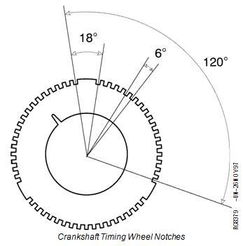
The crank timing wheel (A) is located on the front of the crankshaft, behind the pressed-on crank gear (B). The timing wheel is composed of 54 notches, divided into 3 groups of 18 notches. Before the first notch in each group is a flat area equal to 18 of crankshaft rotation, the following 17 notches are separated by 6 of crankshaft rotation. Each group of 18 notches and a flat area is equal to 120, or a third of a full turn.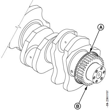
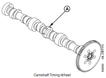
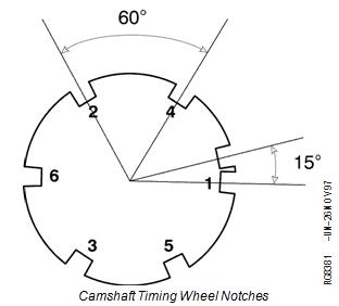
Camshaft Position
The camshaft timing wheel (A) consists of 7 notches cut into the center journal of the camshaft. Six of the 7 notches are evenly spaced at 60 center-to-center. Each of the 6 notches correspond to a cylinder; the 7th notch is located 15 center-to-center before the notch that identifies cylinder number 1. The ECU has the engine firing order stored in memory, therefore it knows that following the notch identifying cylinder 1 will be the notch identifying cylinder 5 etc. The camshaft timing wheel turns at one half the speed of the crankshaft timing wheel.
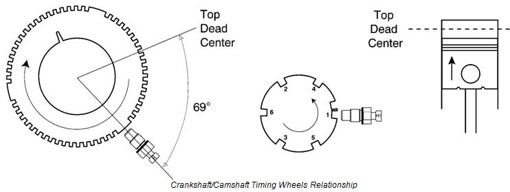
Crankshaft/Camshaft Position Relationship It then monitors each crank timing notch until the time
to start injection occurs, at which time it energizes the When the cam position sensor detects the extra notch Electronic Unit Injector (EUI) solenoid to start fuel
on the cam timing wheel, the ECU is informed that the delivery. notch identifying cylinder 1 is 15 of crank rotation
away from the cam position sensor, and the center of It continues to monitor each crank timing notch until the flat area on the crank timing wheel is 30 of crank the time to end injection occurs, at which time it will rotation away from the crank position sensor. One deenergize the EUI solenoid to stop fuel delivery. timing cycle will then begin when the cam position
sensor is directly in the center of a notch on the cam In the event of a crank or cam position sensor failure, timing wheel. At this time, the crank position sensor is a “limp-home” mode will allow the ECU to operate with directly in the center of a flat area on the crank timing only one position sensor input. If the crank position wheel, and piston number 1 is 69 of crankshaft sensor fails, engine power will be low. If the cam rotation away from TDC on the compression stroke. position sensor fails, long cranking times will be During the previous 120, the ECU calculated engine required to start the engine. If both sensors fail, the speed and determined the optimum time to start engine will die and won’t restart.
injecting fuel and the optimum time to stop injecting (determines fuel amount).
John Deere Qianglu engine parts supply re65168 bearing kit, John Deere Qianglu engine parts supply re64292 O-ring kit, DEUTZ 0413201404132001, Bosch 0445110603 injector, Bosch 0445110603 injector, Mitsubishi 0445110603, Bosch 0445110661 injector, Bosch 0445110661 injector, Mitsubishi 0445110661, Mitsubishi excavator injector 32r61-10010, Mitsubishi 32r6110010 injector, Mitsubishi excavator injector 32r61-00020, Mitsubishi 32r6100020 injector, Bosch 0445120235 injector, Bosch 0445120235 injector, SISU 837073713, Bosch 0445120282 injector, Iveco 50438792950438799295043879290, high pressure relief valve, Bosch 1110010025 relief valve, Hongyan Jess 1110010025 relief valve, johndier Qianglu engine parts supply re31617 sealing ring, johndier Qianglu engine parts supply r545880 gasket, John Deere Qianglu engine parts supply r96935 gasket, John Deere Qianglu engine parts supply r533867 O-ring, John Deere Qianglu engine parts supply r539535 sealing ring, John Deere Qianglu engine parts supply r500374 gasket, Bosch Bosch 0445120608y10005941 injector, Bosch Bosch common rail 0445226092044522619052544845254666cp4n1 oil pump metering unit, Bosch Bosch 09284008001462c00983 metering unit, At493895 engine power wire harness, John Deere engine accessories, dlla133p814 oil nozzle supporting Deere re516540, re519730re507860, se501924, dlla148p82009500-5160re524362, re518725re504181, se501937,