 English
 Espaol
 Franais
 阿拉伯
阿拉伯 中文
中文 Deutsch
 Italiano
 Português
 日本
日本 韩国
韩国 български
 hrvatski
 esky
esky Dansk
Dansk Nederlands
 suomi
suomi Ελληνικ
 印度
印度 norsk
norsk Polski
 Roman
Roman русский
 Svenska
约翰迪尔电子单体喷油器EUI的组成与工作原理强鹿高压共轨喷油器分解图
约翰迪尔电子单体喷油器EUI的组成与工作原理强鹿高压共轨喷油器分解图
Electronic Unit Injector (EUI) Operation on the Dual Rail Fuel System
The electronic unit injector pumping action is created by the up and down movement of the plunger. The plunger movement is caused by the rotation of the camshaft and the rocking action of the rocker arms. The larger return spring will move the plunger up as the camshaft rotates and relaxes the force on the rocker arm.
EUI Fill Cycle - Dual Rail Fuel System
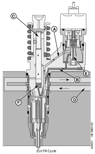
The electronic unit injector will fill with fuel when the plunger (C) is moving up. Fuel from the fuel supply rail (D) enters fuel passage (A) of the unit injector. Fuel flows past the open spill valve (E) into fuel passage (B). Passage B routes fuel into the plunger cylinder (F), which fills as the plunger moves up.
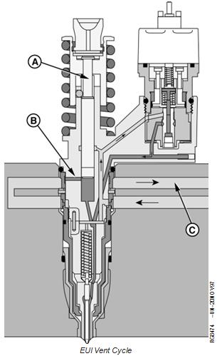
EUI Vent Cycle - Dual Rail Fuel System
The vent cycle begins when the plunger (A) nears the top of the fill cycle stroke. At this point a vent port (B) will be uncovered and fuel and any trapped air can flow to the return fuel rail (C).
EUI Pumping Cycle - Dual Rail Fuel System
The pumping cycle begins when the camshaft lobe pushes on the rocker arm to cause the plunger (F) to start moving down. During the first downward movement of the plunger, the vent port (C) will close.
Further downward movement of the plunger will force fuel from the plunger cylinder (D). Fuel will flow out fuel passage (B), through the open spill valve (E), into fuel passage (A) and back to the fuel supply rail (G). This flow will continue until the injection cycle begins.

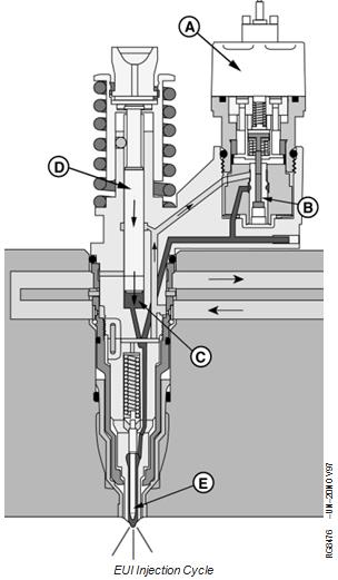
The injection cycle will start when the Engine Control Unit (ECU) energizes the EUI solenoid (A). This will occur during the downward stoke of the plunger.
The energized solenoid will close the spill valve (B). With the spill valve closed, fuel can not escape from the plunger cylinder (C). The downward movement of the plunger (D) will cause the fuel pressure to rise. When the pressure reaches 30,000 kPa (300 bar) (4350 psi), the injector needle (E) will start to move up and injection will begin. As the plunger continues to move down, pressure will rapidly rise to approximately 160,000 kPa (1600 bar) (23,200 psi). Injection will continue until the ECU
de-energizes the solenoid. The spill valve will then open allowing fuel pressure to drop rapidly. The injector needle will close and injection will stop.
Electronic Control System Glossary of Terms
Actuator A device controlled by the (ECU) to perform a certain function.
Analog Signal which has a continuous range of possible voltages. Usually 0 to 5 volt or 0 to 12 volt signals.
Boost Air pressure in the intake manifold.
CAN Controller Area Network. The network on vehicles that allows communication between controllers.
DTC Diagnostic Trouble Code. A code which is stored in the ECU’s memory when the ECU detects a problem in the electronic control system.
DST Diagnostic Scan Tool. The tool used to read and clear DTCs, read sensor and actuator data, and perform engine tests. The DST consists of an Windows (’95 or ’98) or NT compatible computer and 2 kits available from John Deere Distribution Service Center (DSC): JDIS121 - ECU Communication Hardware Kit, and JDIS122 - ECU Communication Software Kit.
Digital A signal which consists of only two-volt levels — usually 0 volts and +5 volts.
ECT Engine Coolant Temperature (sensor). Measures the temperature of the engine coolant. See MEASURING TEMPERATURE later in this Group for details.
ECU Engine Control Unit. The computer which controls the fuel, air, and ignition systems on the engine. See ENGINE CONTROL UNIT (ECU) later in this Group for details.
EUI Electronic Unit Injector. An EUI is an electronically controlled injection pump and injector combined. The ECU controls the start of injection and the amount of fuel injected by energizing and de-energizing the solenoid in the EUI valve housing. See ELECTRONIC UNIT INJECTOR (EUI) OPERATION ON THE DUAL RAIL FUEL SYSTEM or ELECTRONIC UNIT INJECTOR (EUI) OPERATION ON THE SINGLE RAIL FUEL SYSTEM in
Group 130 for details.
FMI Failure Mode Identifier. The second part of a two-part code that identifies control system fault codes according to the J1939 standard. The FMI identifies the type of failure that has occurred. The first half of the code is the Suspect Parameter Number (SPN).
J1587/J1708 The Society of Automotive Engineers (SAE) standard for the electronic components of heavy duty vehicles. J1587 is the software standard. J1708 is the hardware standard.
MAT Manifold Air Temperature (sensor). Measures the temperature of the air in the intake manifold. See MEASURING TEMPERATURE later in this Group for details.
Multi-State A type of throttle that allows the engine to run between 1-3 set engine speeds.
PDM Parallel Data Module. Device used as part of the DST that allows communication with the ECU.
PROM Programmable, Read-Only Memory. The computer chip which contains the calibration information for the engine control system. See ENGINE CONTROL UNIT (ECU) later in this Group for details.
PWM Pulse Width Modulation. A digital signal (not analog) which consists of a pulse generated at a fixed frequency.
When an actuator is controlled by a PWM signal, the on time of the signal is increased or decreased (modulated) to increase or decrease the output of the actuator.
RAM Random Access Memory. The portion of computer memory within the ECU which changes as the engine is running and is stored while the engine is off. See ENGINE CONTROL UNIT (ECU) later in this Group for details.
Sensor Device used by the ECU to monitor various engine parameters.
SPN Suspect Parameter Number. The first half of a two-part code that identifies control system fault codes according to the J1939 Standard. The SPN identifies the system or component that has the failure. The second half of the code is the Failure Mode Identifier (FMI).
TPS Throttle Position Sensor. The TPS measures the position of the throttle, which is controlled by the machine operator. See MEASURING THROTTLE POSITION later in this Group for details.
WIF Water In Fuel Sensor. The WIF detects water in fuel in the water separator bowl on the fuel filter housing.
RG,RG34710,1528 –19–20NOV00–1/1John Deere Qianglu engine parts supply r106829 valve seat insert ring, John Deere Qianglu engine parts supply r106831 valve seat insert ring, John Deere Qianglu engine parts supply r532599 fuel filler pipe, John Deere dz100372 r131575 r360276 piston GASKET KIT, Bosch 044502054 fuel injection pump, Bosch 044502054 oil pump, Finnish SISU 044502054, Finnish SISU 837069146 fuel injection pump, SISU 837069146 common rail oil pump, Bosch 0445020127 fuel injection pump, Bosch0445020127 common rail oil pump, Doosan 044502012733702 repair kit, sdanai 33702 repair kit, Qianglu 33702 repair kit, 33814 repair kit, sdanai 33814 repair kit, Qianglu 33814 repair kit, 32127 nozzle, sdanai 321273920546 nozzle, Qianglu 321273920546 nozzle, sdlla150m31542, sdanai sdlla150m31542, Qianglu sdlla150m31542, sdlla150p42321, sdanai sdlla150p42321, Qianglu sdlla150p42321, John Deere re505052 fuel injection pump, star db4629-5702 fuel injection pump, John Deere re506879 fuel injection pump, star db4327-5736 fuel injection pump, John Deere re503740 fuel injection pump, star db4629-5656 fuel injection pump, John Deere fuel injection pump, re568070re218087re515464re518166, star de2435-5820de2435-5805de2435-5961de2435-5960, star de2435-6255de2435-6247de2435-6322,