配件详情
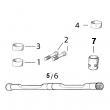
约翰迪尔 4045 4.5T/H 活塞(米)RE515037 排放 2 & 3 (2)
|
|
|
发动机和设备型号
|
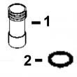
孔径:
4.19 in 106.5 mm
销径 Ø:
1.6250 in (+/- .0002) = 41mm
|
|
|
强鹿JOHN DEERE柴油机配件、发动机配件、发电机组:
T19044、RE62418、RE62419、RE521248、RE520842、C085004、RE509672、RE196945、RE191915、RE522688、RE522687、RE519774、RE532628、RE507980、RE531703、RE24619、RE187966、RE205726、RE507264、RE504836、RE509036、RE533910、RE532952、RE530107、RE508971/
强鹿JOHN DEERE柴油机配件、发动机配件、发电机组:
RE523502、RE518520、RE68345、RE53307、RE62240、RE533095、RE502513、RE38009、R30402、RE521538、RE521540、RE62240、P524837、RE60021、RE507236、RE59588、RE549153、RE530870、SE501610、SE501609、RE70960t77613 9 9900 - 9909 t11370 14 4600 - 4603 t20217 12 2300 - 2333b t77857 44 3500 - 3503 t122075 16 5100 - 5103 t20217 7 2300 - 2333d t77857 8 3700 - 3701 t12275 2 3500 - 3503 t20217 8 2300 - 2335 t77857 10 9900 - 9909 t12275 3 3500 - 3503 t20217 7 2300 - 2335b t78612 7 5900 - 5905 9995-20 powertech 12.5l 6125hf070 engine (waterloo) (esn 030000- ) pc2875 (17-dec-02) pn=676 p r o o f p r o o f powertech 12.5l 6125hf070 engine (waterloo) (esn 030000- ) numerical index - continued part no. grid key page part no. grid key page part no. grid key page t78612 11 5900 - 5907 t78612 13 5900 - 5907 t80622 3 9700 - 9730 t80622 7 9700 - 9732 t80622 1 9700 - 9739 u13639 6 5900 - 5905 u13639 9 5900 - 5907 u13639 15 5900 - 5907 u13639 16 5900 - 5907 u17409 16 5900 - 5903 u17409 12 5900 - 5905 u17409 20 5900 - 5907 u17409 30 9900 - 9909 u40750 20 5900 - 5903 u4662 9 9900 - 9922 u46662 13 9700 - 9724 u46753 44 5900 - 5905 yz101113 3 9700 - 9728 yz101113 3 9700 - 9729 yz102370 2 9700 - 9736 yz102370 2 9700 - 9737 yz104301 2 9700 - 9730 yz104301 6 9700 - 9732 yz104302 3 9700 - 9731 yz104308 7 9700 - 9728 yz104308 7 9700 - 9729 yz104317 13 9700 - 9728 yz104318 3 9700 - 9733 yz104328 1 9700 - 9731 yz104329 1 9700 - 9733 yz104332 4 9700 - 9736 yz104333 4 9700 - 9737 yz104335 6 9700 - 9736 yz104336 6 9700 - 9737 yz104337 3 9700 - 9738 yz104379 6 9700 - 9731 yz104379 6 9700 - 9733 yz104383 3 9700 - 9739 yz110021 2 9700 - 9734 yz110029 2 9700 - 9735 yz110030 4 9700 - 9730 yz110030 8 9700 - 9732 yz110035 2 9700 - 9739 yz110040 6 9700 - 9728 yz110040 6 9700 - 9729 yz110041 4 9700 - 9732 yz110042 4 9700 - 9731 yz110043 4 9700 - 9733 yz110044 3 9700 - 9735 yz250022 1 9700 - 9730 yz250022 5 9700 - 9732 yz250086 4 9700 - 9728 yz250086 4 9700 - 9729 4004247b 9700 - 9731 4004247b 9700 - 9733 4028020 1 9700 - 9740 4028070 2 9700 - 9740 4028145 2 9700 - 9738 powertech 12.5l 6125hf070 engine (waterloo) (esn 030000- ) pc2875 (17-dec-02) 9995-21 pn=677宜宾强鹿JohndeereTO4039皮带涨紧轮供应商,西安约翰迪尔柴油发电机组缸体批发价,上海JohnDeere强鹿柴油机气门导管供应商,吉林约翰迪尔水泵修理包代理商,高雄JohnDeere机油冷却器AR55394信息,新疆约翰迪尔活塞RE529264代理,KEY PART NO. PART NAME QTY SERIAL NO. F F F REMARKS
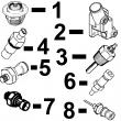
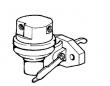
1 R126207 BRACKET 1 X
2 14M7165 LOCK NUT 2 X M6
3 RE504223 SOLENOID 1 X (A) (24 V) (SUB FOR RE54747)
4 19H1914 CAP SCREW 1 X 1/4" X 1"
5 24H1287 WASHER 1 X 9/32" X 5/8" X 0.065"
6 RE54741 LEVER 1 X
7 03M7068 BOLT 1 X M6 X 20
8 19H1900 CAP SCREW 2 X 5/16" X 3/4"
9 24H1136 WASHER 2 X 11/32" X 11/16" X 0.065"
10 R104592 PIPE PLUG 1 X
11 R128694 BASE 1 X (SUB FOR R127415) (ALSO ORDER (2)
R104592)
(A) ENERGIZE TO RUN
METTRE SOUS TENSION POUR FAIRE MARCHER
FUER BETRIEB AKTIVIEREN
ATTIVARE PER IL FUNZIONAMENTO
ACTIVAR PARA MARCHA
MAGNETISERA FOER ATT SAETTA IGAANG
KEY PART NO. PART NAME QTY SERIAL NO. F F F REMARKS
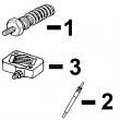
1 21H1319 SCREW 1 X 0.164" X 7/8"
2 12H315 LOCK WASHER 1 X 0.164"
3 24H1136 WASHER 2 X 11/32" X 11/16" X 0.065"
4 19H1900 CAP SCREW 2 X 5/16" X 3/4"
5 R99930 BRACKET 1 X (A)
6 R104675 CLIP 1 X
7 14H605 NUT 1 X 0.164"
8 R104592 PIPE PLUG 1 X
9 R128694 BASE 1 X (SUB FOR R127415) (ALSO ORDER (2)
R104592)
(A) SHUT-OFF
ROBINET D’ARRET
ABSCHALTUNG
RUBINETTO D’ARRESTO
GRIFO DECIERRE
AVSTAENGING
bearing caps—torque . 230 n?m (170 lb-ft) 4. remove cap&compare width of plastigage? with scale provided on wrapper to determine oil clearance. specification crankshaft main bearing-to-journal—oil clearance 0.030—0.107 mm (0.0012—0.0042 in.) plastigage is a registered trademark of dana corp. ctm86 (20mar01) 02-040-22 powertech? 8.1 l diesel engines — base engine 032001 pn=218 crankshaft, main bearings&flywheel repair&adjustment 02 040 23 rg,rg34710,1170 –19–10jun99–1/1 remove connecting rod caps&remove crankshaft rg10209 –un–18jun99 removing connecting rod caps rg10222 –un–18jun99 removing crankshaft a—connecting rod caps b—bearing 1. rotate crankshaft using jdg820/jde81-1 flywheel turning tool until connecting rod caps can be removed easily. you will be able to remove rod caps at each position. 2. remove all connecting rod caps (a) with bearings (b), then remove no. 1&7 main bearing caps and bearings. see remove pistons and connecting rod assemblies in group 030. caution: crankshaft is very heavy. plan a proper handling procedure to avoid injury. note: install a screw on each end of crankshaft to aid in lifting crankshaft. 3. install a cap screw in each end of crankshaft and attach a lifting strap to crankshaft as shown. using proper lifting equipment, carefully raise crankshaft out of cylinder block. 4. clean crankshaft, especially oil passages, using solvent&compressed sir. 5. put crankshaft on clean v-blocks. 6. remove rear wear sleeve from crankshaft flange, if not previously done, using one of the following methods: ? use jdg790 wear sleeve puller to remove wear sleeve from crankshaft, as described earlier in this group. position crankshaft rod journals in v-blocks so that crankshaft does not rotate while removing wear sleeve. ? use the ball side of a ballpeen hammer&tap wear sleeve across its width in a straight line (to deform&stretch sleeve). ? score (but do not cut) the wear sleeve in several places around o.d. with a blunt chisel. ctm86 (20mar01) 02-040-23 powertech? 8.1 l diesel engines — base engine 032001 pn=219 crankshaft, main bearings&flywheel repair&adjustment 02 040 24 rg,rg34710,1171 –19–23oct97–1/2 inspect crankshaft rg5093 –un–05dec97 inspecting crankshaft a—rod journal holes b—journal fillets note: if crankshaft damper damage was discovered during teardown, the crankshaft should be magna-fluxed. this will verify whether of not it has microscopic cracks/fissures. see inspect vibration damper, in this group. 1. thoroughly clean crankshaft. clear restrictions from all oil passages. 2. inspect crankshaft for signs of load stress, cracks, scratches on journals. also check each journal for evidence of excessive overheating/discoloration. if either condition exists, replace crankshaft since heat treatment has probably been destroyed. 3. inspect (front) crankshaft gear&(rear) oil pump drive gear for cracks, chipped teeth,/excessive wear. replace gear(s) as required. see replace crankshaft gear&replace (crankshaft) oil pump drive gear, later in this group. 4. inspect the keyway for evidence of cracks/wear. replace crankshaft as necessary. 5. carefully inspect rear hub of crankshaft in area of wear sleeve contact surface for evidence of rough or grooved condition. any imperfections here will result in oil leaks. slight ridges may be cleaned up with emery or crocus cloths. 6. check each journal for evidence of excessive overheating/discoloration. if either condition exists, replace crankshaft since heat treatment has probably been destroyed. 7. carefully check the crankshaft for cracks in the area of rod journal holes (a)&at journal fillets (b). replace crankshaft if any cracks are found. continued on next page ctm86 (20mar01) 02-040-24 powertech? 8.1 l diesel engines — base engine 032001 pn=220 crankshaft, main bearings&flywheel repair&adjustment 02 040 25 rg,rg34710,1171 –19–23oct97–2/2 important: small cracks may not be visible to the eye. use a method such as the fluorescent magnetic particle method. this method magnetizes the crank, using magnetic particles which are fluorescent&glow under ‘black light’. the crankshaft must be de-magnetized after inspection. rg,rg34710,1172 –19–10jun99–1/2 measure assembled i.d. of bearings and o.d. of crankshaft journals rg10223 –un–18jun99 measuring main bearings note: also inspect&measure assembled i.d. of connecting rod bearings. compare measurements with connecting rod journal o.d. on crankshaft. see inspect&measure connecting rod bearings in group 030. 1. with crankshaft removed from engine, install main bearing caps with bearing inserts. be sure inserts are installed correctly. 2. tighten main bearing cap screws to specifications. specification crankshaft main bearing cap screws—torque 230 n?m (170 lb-ft) 3. measure i.d. of all assembled bearings in four locations 90° apart with an inside micrometer. compare measurements with the following specifications. specification crankshaft main bearing—id with bearing 95.270—95.320 mm (3.7508—3.7528 in.) id without bearing 101.651—101.677 mm (4.0020—4.0030 in.) continued on next page ctm86 (20mar01) 02-040-25 powertech? 8.1 l diesel engines — base engine 032001 pn=221 crankshaft, main bearings&flywheel repair&adjustment 02 040 26 rg,rg34710,1172 –19–10jun99–2/2 rg10224 –un–18jun99 measuring crankshaft main journals 4. measure o.d. of all respective crankshaft main journals in four locations 90° apart. compare measurements with the following specifications. specification crankshaft main journal—od 95.196—95.222 mm (3.7479—3.7490 in.) note: if engine has previously had a major overhaul and undersized bearing inserts were used, i.d. and o.d. dimensions may not be the same as those recorded. however, oil clearance must be 0.030— 0.107 mm (0.0012-0.0042 in.). replace bearings as needed. use crankshaft journal o.d. measurements to determine if journal is out-of-round/tapered. specification crankshaft main journal—taper per 25.4 mm (1.0 in.) length 0.0025 mm (0.0001 in.) out-of-roundness 0.025 mm (0.0010 in.) ctm86 (20mar01) 02-040-26 powertech? 8.1 l diesel engines — base engine 032001 pn=222 crankshaft, main bearings&flywheel repair&adjustment 02 040 27 rg,rg34710,1173 –19–10jun99–1/2 main bearing cap line bore specifications rg10223 –un–18jun99 measuring main bearing cap bores if any main bearing cap assembled i.d. is not within specification, blank (generic) bearing caps are available and must be line bored to specification. replace individual bearing caps as needed. 1. measure main bearing cap surface width. specification crankshaft main bearing cap— surface width 36.28—36.78 mm (1.428—1.448 in.) 2. with crankshaft removed from cylinder block, install main bearing caps without bearing inserts. 3. tighten main bearing cap screws to specifications. specification crankshaft main bearing cap screws—torque 230 n?m (170 lb-ft) 4. measure i.d. of all bearing caps with an inside micrometer. main bearing cap i.d. should be as follows: specification main bearing assembled id—id 95.270—95.320 mm (3.7508—3.7528 in.) if any main bearing cap assembled i.d. is not within specification, blank (generic) bearing caps are available and must be line bored to finished specification. replace individual bearing caps as needed. continued on next page ctm86 (20mar01) 02-040-27 powertech? 8.1 l diesel engines — base engine 032001 pn=223 crankshaft, main bearings&flywheel repair&adjustment 02 040 28 rg,rg34710,1173 –19–10jun99–2/2 important: main bearing cap line boring should be done only by experienced personnel on equipment capable of maintaining bore specifications. specification main bearing cap bore—id without bearings (standard) 101.651—101.677 mm (4.0020—4.0030 in.) . diameter variation 0.013 mm (0.0005 in.) maximum diameter taper . 0.008 mm (0.0003 in.) maximum straightness variation (any bore-to-adjacent bore) . 0.038 mm (0.0015 in.) maximum straightness variation (5 center bore-to-end bore 0.076 mm (0.0030 in.) maximum centerline of bore-to-top deck 352.35—352.50 mm (13.872—13.878 in.) rg,rg34710,1174 –19–10jun99–1/1 thrust bearing new part specifications rg5269 –un–20nov97 thrust bearing measurements a—thrust washer clearance base circle b—thrust surface thickness c—relief angle d—bearing cap overall width important: install thrust bearing in cylinder block and tighten to specification before regrinding/polishing thrust surfaces to assure that all surfaces on bearing and on block web are correctly aligned. specification a—thrust washer clearance1— base circle od 129.286—130.810 mm (5.09—5.15 in.) . b—thrust bearing cap—surface width 37.44—37.54 mm (1.474—1.478 in.) c—thrust washer clearance— relief angle 45° d—thrust bearing cap—overall width ( —1995) 41.81—42.31 mm (1.646—1.666 in.) . overall width (1995—) 39.16—39.66 mm (1.542—1.561 in.) maximum runout for thrust surface is as follows: specification thrust bearing surface— maximum runout .怒江约翰迪尔6068柴油机水泵盖厂家供货,巴中约翰迪尔4045连杆R81410一级代理,齐齐哈尔约翰迪尔活塞RE22678多少钱,邢台强鹿柴油机曲轴RE515785哪家买,宁德约翰迪尔6068柴油机气门弹簧的价格,铁岭约翰迪尔装载机发动机电脑板哪里买,怒江JohnDeere连杆瓦R116081批发商,黑河约翰迪尔滤清器RE504836公司,西宁强鹿柴油机四配套IK526975市场报价,广安强鹿柴油机4045主轴瓦价格行情,海口约翰迪尔6081发动机水泵O型圈找哪家,商丘约翰迪尔进气门异管RE518082一级代理,泰安约翰迪尔CH530甘蔗收获机发动机配件供货商,玉林强鹿柴油机水泵RE530870厂家供货,承德约翰迪尔发动机飞轮壳代理商,鹤壁强鹿4045大修件RE527299厂家批发,湘潭JOHNDEERE强鹿6068TF250配件价格行情,澳门离岛约翰迪尔柴油机连杆衬套TR114082诚信推荐,宝鸡强鹿6068柴油机传感器找哪家,九龙强鹿6068柴油机张紧轮供货商,通化约翰迪尔强鹿4045缸套找哪家,咸阳约翰迪尔强鹿连杆螺丝R501035批发价,衢州约翰迪尔联合收割机发动机喷油嘴哪家买,绍兴强鹿6090柴油机加大止推轴承瓦找哪家,抚州强鹿6081发动机连杆瓦哪家好,漯河强鹿柴油机增压器RE509818的价格,清远JohnDeereRE55343凸轮轴衬套哪里买,苏州强鹿柴油机止推瓦RE65168的价格,三亚美国约翰迪尔输油泵RE68345代理商,福州强鹿6090柴油机大修包信息,宝鸡强鹿6068柴油机传感器厂家价格,昭通JohnDeere传感器RE167207批发价,资阳约翰迪尔柴油发电机组副线束诚信推荐,安阳强鹿燃油泵RE502513供货商,河南强鹿3029TF120发动机配件代理商,吕梁johndeere约翰迪尔强鹿柴油发动机缸垫R116516代理商,台北强鹿柴油机缸套阻水圈AR72351厂家批发,三亚美国约翰迪尔输油泵RE68345价格,丹东强鹿RE27368主轴瓦供货商,庆阳约翰迪尔气门弹簧R518872哪家好,茂名约翰迪尔修理包RE527833供应商,临沧强鹿6068柴油机油泵一级代理,恩施约翰迪尔挖掘机全车线束批发,大理约翰迪尔柴油发电机组凸轮轴厂家价格,运城强鹿6068柴油机连杆铜套代理,澳门离岛强鹿柴油机泵头厂家价格,衢州约翰迪尔6090柴油机主轴瓦哪里买,濮阳约翰迪尔4045柴油机张紧轮RE518097信息, 0.25 mm (0.0010 in.) 1 thrust (washer) surfaces on bearing cap must be flat in respect to mating thrust (washer) surfaces in cylinder block. ctm86 (20mar01) 02-040-28 powertech? 8.1 l diesel engines — base engine 032001 pn=224 crankshaft, main bearings&flywheel repair&adjustment 02 040 29 dpsg,ouo1004,907 –19–16jun99–1/2 crankshaft grinding guidelines important: crankshaft grinding should be done only be experienced personnel on equipment capable of maintaining crankshaft size&finish specifications. crankshaft rod (pin) journals have an undercut fillet radius. do not grind within this undercut area when undersize bearings are used. in addition to the standard size main bearings, 0.292 mm (0.0115 in.)&0.552 mm (0.0217 in.) undersize bearings are available for main bearing journals. specification undersized main bearings available—od 0.292 mm (0.0115 in.) and 0.552 mm (0.0217 in.) rod (pin) journals have only 0.292 mm (0.0115 in.) undersize bearings only. specification undersized rod (pin) journal bearings available—od 0.292 mm (0.0115 in.) if journals are tapered, out-of-round, scored, or damaged, grind the crankshaft&install the proper undersize bearings. important: if undersize bearings are used, check bearing clearance after bearing caps have been tightened to specified torque. if undersize bearings are too tight&clearance is not within specifications, the journal&bearing will be wiped clean of all oil. this would result in premature wear of parts. if the crankshaft is to be reground, use the following recommended guidelines: 1. compare the crankshaft journal measurements taken during inspection&determine the size to which the journals are to be reground. 2. grind all main journals/all connecting rod journals to the same required size. see crankshaft grinding specifications later in this group. important: all main journal (tangential) fillets radii must be free of any sharp grind marks/scratches. the fillet must blend smoothly into the journal and crank cheek. check the radii with a fillet gauge. care must be taken to avoid localized heating which often produces grinding cracks. cool the crankshaft while grinding by using coolant generously. do not crowd the grinding wheel into the work. grind crankshaft with journals turning counterclockwise, as viewed from the front end of the crankshaft. lap/polish journals in opposite direction of grinding. 3. polish/lap the ground surfaces to the specified finish to prevent excessive wear of the journals. continued on next page ctm86 (20mar01) 02-040-29 powertech? 8.1 l diesel engines — base engine 032001 pn=225 crankshaft, main bearings&flywheel repair&adjustment 02 040 30 dpsg,ouo1004,907 –19–16jun99–2/2 note: production crankshafts are induction hardened and shotpeened at the factory. field shotpeening is not recommended due to the equipment required&part geometry. when thrust surfaces are reground&an oversized washer is used, crankshaft end play specification must be maintained to within 0.038—0.380 mm (0.0015—0.0150 in.). see check crankshaft end play earlier in this group. 4. if the thrust surfaces of the crankshaft are worn or grooved excessively, regrind&polish. maintain the specified radius between each thrust surface and the bearing journal. an oversized thrust washer and two 0.18 mm (0.007 in.) oversized washers are available. see thrust bearing new part specifications earlier in this group. specification oversize thrust washer available—od . 0.18 mm (0.007 in.) crankshaft—end play 0.038—0.380 mm (0.0015—0.0150 in.) 5. stone the edge of all oil holes in the journal surfaces smooth to provide a radius of approximately 1.50 mm (0.060 in.). 6. when finished grinding, inspect the crankshaft for cracks with the fluorescent magnetic particle method,/similar method. de-magnetize crankshaft after inspection. 7. thoroughly clean the crankshaft&oil passages with solvent. dry with compressed air. ctm86 (20mar01) 02-040-30 powertech? 8.1 l diesel engines — base engine 032001 pn=226 crankshaft, main bearings&flywheel repair&adjustment 02 040 31 rg,rg34710,1176 –19–23oct97–1/1 crankshaft grinding specifications item measurement specification engine stroke length 128.5 mm (5.059 in.) main&rod journal surface finish lap 0.20 um (8 aa) thrust journal surface finish lap 0.40 um (16 aa) rod journal (undercut) fillet radius 4.10—4.37 mm (0.158—0.172 in.) main journal (tangential) fillet radius 3.94—4.44 mm (0.155—.0175 in.) thrust journal (tangential) fillet radius 3.56—4.06 mm (0.140—0.160 in.) thrust journal width 44.387—44.487 mm (1.7475— 1.7515 in.) crankshaft main journal maximum runout relative to no. 1 0.13 mm (0.0051 in.) and no. 7 journals crankshaft main journal maximum runout between adjacent 0.06 mm (0.0024 in.) cylinders crankshaft main journal (using od 95.201—95.227 mm (3.7480— standard bearings) 3.7491 in.) crankshaft rod journal (using od 76.149—76.175 mm (2.9980— standard bearings) 2.9990 in.)本溪强鹿机滤RE509672找哪家,景德镇约翰迪尔6090柴油机加大主轴瓦批发,六安JohnDeere加大止推轴承瓦RE65168B代理,鹤壁强鹿曲轴齿轮R104587批发,吐鲁番JohnDeere温器座RE64354多少钱,温州约翰迪尔4045柴油机连杆RE500608批发,澳门半岛johndeere约翰迪尔强鹿柴油发动机连杆瓦RE65908代理商,吴忠强鹿柴油滤芯RE521248哪家好,贵港约翰迪尔联合收割机发动机缸盖厂家批发,湖北JohnDeere进气门R520223一级代理,海西约翰迪尔柴油机排气门导管R119132代理商,鄂尔多斯johndeere约翰迪尔强鹿柴油机涡轮增压器厂家批发, crankshaft main journal (using od 94.909—94.935 mm (3.73666— 0.292 mm (0.0115 in.) undersize 3.7376 in.) bearings) crankshaft rod journal (using 0.292 od 75.857—75.883 mm (2.9865— mm (0.0115 in.) undersize bearings) 2.9875 in.) crankshaft main journal (using od 94.649—94.675 mm (3.7263— 0.552 mm (0.0217 in.) undersize 3.7274 in.) bearings)1 10.552 mm (0.0217 in.) undersize bearing sizes are available for crankshaft main journals only. ctm86 (20mar01) 02-040-31 powertech? 8.1 l diesel engines — base engine 032001 pn=227 crankshaft, main bearings&flywheel repair&adjustment 02 040 32 rg,rg34710,1177 –19–23oct97–1/1 replace (crankshaft) oil pump drive gear rg5018 –un–05dec97 removing crankshaft oil pump drive gear a—weld beads b—gear important: protect all machined surfaces of crankshaft from grinding debris and weld spatter when removing old gear and installing new gear. do not use a cutting torch to remove failed gear. 1. using a rotary grinding wheel/parting disc, grind weld beads (a) until flush with crankshaft flange. 2. remove gear (b) by alternately striking gear at each weld location using a brass drift&soft lead mallet. 3. after removal of gear, clean up o.d. of crankshaft flange&remove any burrs/remaining weld bead to eliminate interference when installing new gear. caution: oil fumes/oil can ignite above 193°c (380°f). use a thermometer&do not exceed 182°c (360°f). do not allow a heating element to be in direct contact with the oil. heat the oil in a well-ventilated area. plan a safe handling procedure to avoid burns. important: do not overheat gear. see caution. overheating may also destroy original heat treatment of gear. 4. heat crankshaft gear to 148°c (300°f) using either heated oil/oven heat. 5. drive gear onto crankshaft flange until flush against shoulder. note: when driving oil pump onto crankshaft flange, the beveled edge of gear teeth should face the flywheel end of crankshaft. 6. weld two 25.4 mm (1 in.) beads according to illustration using 1/8 in. diameter 7018 welding rod. grind away excess weld to eliminate the possibility of interference with cylinder block. ctm86 (20mar01) 02-040-32 powertech? 8.1 l diesel engines — base engine 032001 pn=228 crankshaft, main bearings&flywheel repair&adjustment 02 040 33 rg,rg34710,1178 –19–23oct97–1/1 replace crankshaft gear note: remove crankshaft gear for replacement only; it is not necessary to remove gear for crankshaft removal. 1. install jdg787 thread protector in nose of crankshaft. 2. protect crankshaft wear sleeve surface with masking tape. 3. remove crankshaft gear using d01251aa1 puller or an equivalent puller. 4. discard gear after removal. 5. remove woodruff key from crankshaft keyway. 6. remove masking tape. caution: oil fumes/oil can ignite above 193°c (380°f). use a thermometer&do not exceed 182°c (360°f). do not allow a heating element to be in direct contact with the oil. heat the oil in a well-ventilated area. plan a safe handling procedure to avoid burns. important: crankshaft gear must be installed on crankshaft before crankshaft is installed in engine, otherwise damage to thrust bearings could occur. if flame heat is used, be sure gear is heated uniformly around circumference. do not overheat. see caution. overheating may also destroy original heat treatment of gear. 7. heat crankshaft gear (if removed) to 148°c (300°f), using either heated oil/oven heat. 8. install woodruff key in crankshaft. 9. place gear on crankshaft flange. be sure key on crankshaft is properly aligned with keyway in gear. important: when installing gear, do not gouge or nick crankshaft flange. 10. use jdh7 driver to firmly seat gear against crankshaft flange. 11. once gear cools, reseat gear using jdh7 driver. 1part of d01047aa 17-1/2&30-ton puller set. ctm86 (20mar01) 02-040-33 powertech? 8.1 l diesel engines — base engine 032001 pn=229 crankshaft, main bearings&flywheel repair&adjustment 02 040 34 rg,rg34710,1179 –19–23oct97–1/1 inspect thrust bearings r24545n –un–04dec97 crankshaft main thrust bearing assembly a—lower rear thrust washer b—upper rear thrust washer c—lower front thrust washer d—main bearing block thrust bearing e—main bearing cap thrust bearing f—large tang g—small tang check thrust surfaces of the thrust bearing&the thrust bearing journal on crankshaft&replace as necessary. thrust bearing are available in each of the previously mentioned insert undersizes. an oversized thrust washer set containing one regular size washer&two 0.18 mm (0.007 in.) oversized washers is also available. specification crankshaft oversize thrust washers available—od . 0.18 mm (0.007 in.) note: thrust bearing must be installed with slots facing crankshaft flange. two halves (a)&(c) go on cap side, not block. dpsg,ouo1004,893 –19–10jun99–1/1 remove&clean piston cooling orifices rg10211 –un–18jun99 piston cooling orifices in block a—piston cooling orifices 1. remove all six (four shown) piston cooling orifices (a) and inspect each cooling orifice to make sure it is not plugged/damaged. 2. use a soft wire&compressed air to clean orifice. replace if condition is questionable. important: a piston cooling orifice failure could cause damage to pistons, piston pins, rod pin bushings,&liners. if a piston cooling orifice is left out, low/no oil pressure will result. 3. install orifices&tighten to specifications. specification piston cooling orifices into cylinder block—torque 11 n?m (97 lb-in.) ctm86 (20mar01) 02-040-34 powertech? 8.1 l diesel engines — base engine 032001 pn=230 crankshaft, main bearings&flywheel repair&adjustment 02 040 35 rg,rg34710,1181 –19–10jun99–1/3 install main bearings&crankshaft r24545n –un–04dec97 no. 5 main thrust bearing assembly a—lower rear thrust washer b—upper rear thrust washer c—lower front thrust washer d—main bearing block thrust bearing e—main bearing cap thrust bearing f—large tang g—small tang important: if new main/thrust bearing inserts or thrust washers are installed, they must be installed as a matched set. during assembly, apply a liberal coating of clean engine oil to: ? all main bearing webs in block ? both sides of main bearing inserts&thrust bearing inserts ? entire o.d. of crankshaft main bearing journal 1. install six main bearing inserts in block except no. 5 thrust bearing insert. be sure locating tabs on inserts are properly positioned with slot in block web. important: thrust washers (a, c) go on both sides of bearing cap. thrust washer (b) goes on rear side of block web only with the slots facing the crankshaft. 2. install no. 5 main thrust bearing insert (d) in block. install upper thrust washer on bearing insert at rear of block web. be sure tangs on washer are properly positioned on thrust bearing insert. 3. check to make sure that oil holes in main bearing web are properly aligned with oil holes in bearing inserts. continued on next page ctm86 (20mar01) 02-040-35 powertech? 8.1 l diesel engines — base engine 032001 pn=231 crankshaft, main bearings&flywheel repair&adjustment 02 040 36 rg,rg34710,1181 –19–10jun99–2/3 rg10222 –un–18jun99 installing crankshaft rg10226 –un–18jun99 installing main bearing caps rg11640 –un–22dec00 stamped main bearing cap a—cap screw with washer b—bearing cap c—bearing d—stamped cylinder number e—stamped arrow caution: crankshaft is heavy. plan a proper lifting procedure to avoid injuries. 4. carefully position crankshaft onto main bearing inserts using a hoist&lift sling, as shown. 5. dip entire main bearing cap screws in clean engine oil and position them in main bearing caps. apply a liberal amount of oil to bearing inserts in caps. 6. install each bearing cap (b), bearings (c),&cap screws with washer (a) with the recesses&tabs aligned in matching order. make sure bearing tabs also match up before tightening cap screws. note: make sure main bearing caps are installed on the bearing bosses from which they were removed. the numbers (d) stamped on the caps should be on the same side as the numbers on the block. bearing caps on later engines have the numbers 1—7 stamped on top face&block castings have only the no. 1&no. 7 cylinders stamped for reference. if there is an arrow (e) on cap, arrow is normally on the camshaft side of the block&should be pointing towards the front of the engine. on some engines, arrows on caps may be pointing towards the rear of the engine. reinstall these caps with arrows pointing toward rear of engine. if bearing caps have been rebored, make sure bearing caps have numbers stamped on them. important: do not use pneumatic wrench to install main bearing cap screws, as damage may occur to threads. 7. before tightening cap screws on main bearing caps, align upper&lower thrust flanges on main thrust bearings. using a soft-face hammer, tap crankshaft to the rear&then to the front to line up thrust bearing flanges. 8. tighten no.’s 1, 2, 3, 4, 6,&7 main bearing cap screws to initial torque specifications. ctm86 (20mar01) 02-040-36 powertech? 8.1 l diesel engines — base engine 032001 pn=232 continued on next page crankshaft, main bearings&flywheel repair&adjustment 02 040 37 rg,rg34710,1181 –19–10jun99–3/3 specification crankshaft main bearing cap screws—initial torque 68 n?m (50 lb-ft) hand-tighten no. 5 main thrust bearing cap screws. 9. gently pry crankshaft rearward&then forward to align thrust washers on no. 5 main thrust bearing. note: do not pry crankshaft on no. 5 main thrust bearing. 10. tighten no. 5 main thrust bearing cap screws to specification above. 11. tighten all main bearing cap screws (including no. 5) to final torque specification. specification crankshaft main bearing cap screws—final torque . 230 n?m (170 lb-ft) 12. turn crankshaft by hand. if it does not turn easily, disassemble parts&determine the cause. 13. install connecting rod bearings&connecting rods caps. see install piston&connecting rod in group 030. 14. check crankshaft for specified end play. specification crankshaft—end play 0.038—0.380 mm (0.00150—0.0150 in.) . 15. install oil pump&check drive gear-to-crankshaft clearance. see install engine oil pump in group 060. specification oil pump drive gear-to-crankshaft—backlash clearance . 0.38 mm (0.015 in.) ctm86 (20mar01) 02-040-37 powertech? 8.1 l diesel engines — base engine 032001 pn=233 crankshaft, main bearings&flywheel repair&adjustment 02 040 38 rg,rg34710,1182 –19–23oct97–1/2 install crankshaft rear oil seal housing rg4637 –un–05dec97 installing crankshaft rear oil seal housing (engine shown upside down in stand) a—crankshaft flange b—oil seal housing id c—oil seal housing note: on engines with john deere (funk) rear pto, see ctm67, oem engine acces***ies for procedure to install rear oil seal housing. these instructions are for when oil seal housing&oil pan have been removed from cylinder block. 1. make sure the o.d. of crankshaft flange (a)&i.d. of seal housing (b) are free from nicks/burrs. restore damaged surfaces with a fine file/emery cloth. clean with compressed air. 2. install oil seal housing (c) on cylinder block using a new gasket. install all six cap screws with washers, using loctite? 242 on threads. tighten screws finger tight. loctite is a registered trademark of loctite corp. continued on next page ctm86 (20mar01) 02-040-38 powertech? 8.1 l diesel engines — base engine 032001 pn=234 crankshaft, main bearings&flywheel repair&adjustment 02 040 39 rg,rg34710,1182 –19–23oct97–2/2 rg7049 –un–05dec97 centering rear oil seal housing rg6427 –un–05dec97 cap screw tightening sequence for rear oil seal housing a—jdg796 alignment tool important: alignment&installation tools must be clean to hold runout within specification&to assure proper positioning on crankshaft flange so oil seal does not fail prematurely. 3. slip the jdg796 alignment tool (a) over crankshaft flange&into seal housing bore to center oil seal housing. the tool is designed to center the oil seal housing in relation to crankshaft flange. however, measuring the seal housing runout after installation with a magnetic base dial indicator is recommended. runout should not exceed specification. specification crankshaft rear oil seal housing id—maximum runout 0.152 mm (0.006 in.) 4. using a straightedge, position bottom of oil seal housing so it is recessed 0.000—0.050 mm (0.000— 0.002 in.) inside cylinder block-oil pan rail. specification rear oil seal housing-to-oil pan rail—recess 0.000—0.050 mm (0.000—0.002 in.) inside block oil pan rail . tighten seal housing cap screws to specifications using sequence shown in bottom illustration, beginning with cap screw no. 1. specification rear crankshaft oil seal housing—torque . 27 n?m (20 lb-ft) 5. remove alignment tool from end of crankshaft flange. 6. check oil seal housing runout with a magnetic base dial indicator. see check crankshaft rear oil seal housing runout later in this group. 7. trim off excess gasket material extending below bottom of oil seal housing. ctm86 (20mar01) 02-040-39 powertech? 8.1 l diesel engines — base engine 032001 pn=235 crankshaft, main bearings&flywheel repair&adjustment 02 040 40 rg,rg34710,1183 –19–23oct97–1/1 check crankshaft rear oil seal housing runout rg5751 –un–05dec97 checking rear oil housing runout a—magnetic base dial indicator b—oil seal housing bore important: on service “short block” assemblies, rear oil seal housing runout is preset at the factory. do not remove housing from block. 1. position magnetic base dial indicator (a) on end of crankshaft flange as shown. preset dial indicator tip on i.d. of oil seal housing bore (b). 2. zero dial indicator&rotate crankshaft one full revolution, observe full indicator movement. the maximum oil seal housing bore runout is as follows: specification crankshaft rear oil seal housing—maximum runout . 0.152 mm (0.006 in.) if runout exceeds specification, loosen cap screws and adjust housing to obtain an acceptable runout while keeping bottom of seal housing flush with oil pan mating surface. 3. recheck oil seal housing bore runout. if runout still exceeds specification, oil seal housing bore is possibly distorted&should be replaced. see install crankshaft rear oil seal housing, earlier in this group. ctm86