配件详情
麦克福斯约翰迪尔发动机零配件
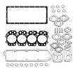
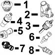
约翰迪尔 4045 4.5T/H 活塞(米)RE515037 排放 2 & 3 (2)
|
|
|
发动机和设备型号
|
孔径:
4.19 in 106.5 mm
销径 Ø:
1.6250 in (+/- .0002) = 41mm
|
|
|
强鹿JOHN DEERE柴油机配件、发动机配件、发电机组:
RE509032、RE59754、RE507284、RE59754、RE519626、RE508202、RE58935、T19044、RE62418、RE62419、RE521248、RE520842、C085004、RE509672、RE196945、RE191915、RE522688、RE522687、RE519774、RE532628、RE507980、RE531703、RE24619/
强鹿JOHN DEERE柴油机配件、发动机配件、发电机组:
RE187966、RE205726、RE507264、RE504836、RE509036、RE533910、RE532952、RE530107、RE508971、RE523502、RE518520、RE68345、RE53307、RE62240、RE533095、RE502513、RE38009、R30402、RE62240、P524837、RE60021、RE507236、RE59588、RE549153、RE530870、SE501610、SE501609、RE70960/
直销美国强鹿JOHN DEERE柴油机配件、发动机配件、发电机组: 3029DF120、3029TF158、3029TFU80、3029HFU70、4045HF280、4045TF002、3029DF128、30294045TF258、4045TF275、4045TF220、4045HF285、4045TF258、4045TFU70、4045HF285V07、4045TF220(waterloo) (esn 030000- ) pc2875 (17-dec-02) i-23 pn=29 p r o o f p r o o f powertech 12.5 l marine engine (waterloo) memoranda memoranda memoranda memoranda memoranda memoranda 000i-24 powertech 12.5l 6125hf070 engine (waterloo) (esn 030000- ) pc2875 (17-dec-02) pn=30 p r o o f p r o o f valve cover sectional index index de section gruppenindex indice della sezione indice de seccion gruppsforteckning rgp5333 -un-31jan01 1101 - powertech 12.5l 6125hf070 engine (waterloo) (esn 030000- ) pc2875 (09-jan-02) 1100-a01 pn=31 p r o o f p r o o f valve cover sectional index index de section gruppenindex indice della sezione indice de seccion gruppsforteckning 1101 - 1100-a02 powertech 12.5l 6125hf070 engine (waterloo) (esn 030000- ) pc2875 (22-dec-00) pn=32 p r o o f p r o o f valve cover 1101 1101 1101 1101 1101 1101 rgp5334 -un-14jul99 engine key part no. part name qty serial no. remarks 1 19m8039 screw 3 m8 x 80 2 re71265 isolator 3 3 r120467 elbow fitting 1 4 ty22467 clamp 1 5 ty22450 bulk hose ar 6 r72328 o-ring 1 (nlr) 7 r116843 valve cover 1 -014582 r505450 valve cover 1 014583- 8 r63185 o-ring 1 9 re66329 deflector 1 10 r130738 gasket 1 -014582 r502124 gasket 1 014583- 11 r130091 screw 2 m6 x 12 12 r501292 bushing 2 (sub for r127451) 13 r132985 medallion 1 powertech 12.5l 6125hf070 engine (waterloo) (esn 030000- ) pc2875 (22-aug-01) 1100-1101 pn=33 p r o o f p r o o f valve cover memoranda memoranda memoranda memoranda memoranda memoranda 1100-1102 powertech 12.5l 6125hf070 engine (waterloo) (esn 030000- ) pc2875 (22-dec-00) pn=34 p r o o f p r o o f oil filler neck sectional index index de section gruppenindex indice della sezione indice de seccion gruppsforteckning rgp7210 -un-31jan01 1201 - 1202 - 1203 - 1204 - 1206 - 1207 - 1208 - 1209 - powertech 12.5l 6125hf070 engine (waterloo) (esn 030000- ) pc2875 (09-jan-02) 1200-a01 pn=35 p r o o f p r o o f oil filler neck sectional index index de section gruppenindex indice della sezione indice de seccion gruppsforteckning 1201 - 1202 - 1203 - 1204 - 1206 - 1207 - 1208 - 1209 - 1200-a02 powertech 12.5l 6125hf070 engine (waterloo) (esn 030000- ) pc2875 (22-dec-00) pn=36 p r o o f p r o o f oil filler neck 1201 1201 1201 1201 1201 1201 rgp5359 -un-13aug99 engine key part no. part name qty serial no. remarks 1 r36636 fitting plug 1 2 r29936 o-ring 1 powertech 12.5l 6125hf070 engine (waterloo) (esn 030000- ) pc2875 (22-aug-01) 1200-1201 pn=37 p r o o f p r o o f oil filler neck 1202 1202 1202 1202 1202 1202 rgp5360 -un-09sep99 engine key part no. part name qty serial no. remarks 1 re500250 filler cap 1 2 19m7804 screw 2 m10 x 40 3 re505718 tube 1 (l.h.) (front) 4 ar44217 clamp 2 5 r133758 hose 1 6 au14063 hose fitting 1 7 r29936 o-ring 3 8 r36636 fitting plug 3 1200-1202 powertech 12.5l 6125hf070 engine (waterloo) (esn 030000- ) pc2875 (22-aug-01) pn=38 p r o o f p r o o f oil filler neck 1203 1203 1203 1203 1203 1203 rgp5360 -un-09sep99 engine key part no. part name qty serial no. remarks 1 re500250 filler cap 1 2 19m7804 screw 2 m10 x 40 3 re505718 tube 1 (l.h.) (rear) 4 ar44217 clamp 2 5 r133758 hose 1 6 au14063 hose fitting 1 7 r29936 o-ring 3 8 r36636 fitting plug 3 powertech 12.5l 6125hf070 engine (waterloo) (esn 030000- ) pc2875 (22-aug-01) 1200-1203 pn=39 p r o o f p r o o f oil filler neck 1204 1204 1204 1204 1204 1204 rgp5360 -un-09sep99 engine key part no. part name qty serial no. remarks 1 re500250 filler cap 1 2 19m7804 screw 2 m10 x 40 3 re505718 tube 1 (r.h.) (front) 4 ar44217 clamp 2 5 r133758 hose 1 6 au14063 hose fitting 1 7 r29936 o-ring 3 8 r36634 spring 3 1200-1204 powertech 12.5l 6125hf070 engine (waterloo) (esn 030000- ) pc2875 (22-aug-01) pn=40 p r o o f p r o o f oil filler neck 1206 1206 1206 1206 1206 1206 rgp5361 -un-13aug99 engine key part no. part name qty serial no. remarks 1 r36636 fitting plug 5 2 r29936 o-ring 5 powertech 12.5l 6125hf070 engine (waterloo) (esn 030000- ) pc2875 (22-aug-01) 1200-1205 pn=41 p r o o f p r o o f oil filler neck 1207 1207 1207 1207 1207 1207 rgp5360 -un-09sep99 engine key part no. part name qty serial no. remarks 1 re500250 filler cap 1 2 19m7804 screw 2 m10 x 40 3 re68818 tube 1 -010816 (l.h.) (front) re505718 tube 1 010817- 4 ar44217 clamp 2 5 r133758 hose 1 6 au14063 hose fitting 1 7 r29936 o-ring na 8 r36636 fitting plug na 1200-1206 powertech 12.5l 6125hf070 engine (waterloo) (esn 030000- ) pc2875 (22-aug-01) pn=42 p r o o f p r o o f oil filler neck 1208 1208 1208 1208 1208 1208 rgp5360 -un-09sep99 engine key part no. part name qty serial no. remarks 1 re500250 filler cap 1 2 19m7804 screw 2 m10 x 40 3 re505718 tube 1 (l.h.) (front) 4 ar44217 clamp 2 5 r133758 hose 1 6 au14063 hose fitting 1 7 r29936 o-ring 2 8 r36636 fitting plug 2 powertech 12.5l 6125hf070 engine (waterloo) (esn 030000- ) pc2875 (22-aug-01) 1200-1207 pn=43 p r o o f p r o o f oil filler neck 1209 1209 1209 1209 1209 1209 rgp5360 -un-09sep99 engine key part no. part name qty serial no. remarks 1 re500250 filler cap 1 2 19m7804 screw 2 m10 x 40 3 re505718 tube 1 (r.h.) (front) 4 ar44217 clamp 2 5 r133758 hose 1 6 au14063 hose fitting 1 7 r29936 o-ring 2 8 r36636 fitting plug 2 1200-1208 powertech 12.5l 6125hf070 engine (waterloo) (esn 030000- ) pc2875 (22-aug-01) pn=44 p r o o f p r o o f crankshaft pulley sectional index index de section gruppenindex indice della sezione indice de seccion gruppsforteckning rgp7211 -un-31jan01 1301 - 1302 - 1303 - 1304 - 1305 - 1306 - 1307 - 1308 - 1309 - 1311 - 1312 - 1313 - 1314 - powertech 12.5l 6125hf070 engine (waterloo) (esn 030000- ) pc2875 (09-jan-02) 1300-a01 pn=45 p r o o f p r o o f crankshaft pulley memoranda memoranda memoranda memoranda memoranda memoranda 1300-a02 powertech 12.5l 6125hf070 engine (waterloo) (esn 030000- ) pc2875 (22-dec-00) pn=46 p r o o f p r o o f crankshaft pulley 1301 1301 1301 1301 1301 1301 rgp5349 -un-13aug99 engine key part no. part name qty serial no. remarks 1 re54073 seal 1 (front) 2 r130091 screw 8 3 re505520 torsional dampener 1 (sub for re505506) 4 r501561 hub 1 5 19m7818 screw 6 m12 x 80 powertech 12.5l 6125hf070 engine (waterloo) (esn 030000- ) pc2875 (22-aug-01) 1300-1301 pn=47 p r o o f p r o o f crankshaft pulley 1302 1302 1302 1302 1302 1302 rgp7106 -un-05dec00 engine key part no. part name qty serial no. remarks 1 re54073 seal 1 (front) 2 r130091 screw 8 3 re65565 torsional dampener 1 4 r501561 hub 1 5 19m7818 screw 6 m12 x 80 6 r133879 pulley 1 7 19m7818 screw 4 m12 x 80 1300-1302 powertech 12.5l 6125hf070 engine (waterloo) (esn 030000- ) pc2875 (22-aug-01) pn=48 p r o o f p r o o f crankshaft pulley 1303 1303 1303 1303 1303 1303 rgp7107 -un-05dec00 engine key part no. part name qty serial no. remarks 1 re54073 seal 1 (front) 2 r130091 screw 8 3 re505520 torsional dampener 1 (sub for re505506) 4 r501561 hub 1 5 19m7818 screw 6 6 r133880 pulley 1 7 19m7818 screw 4 powertech 阳江强鹿R97341机油底壳垫片厂家批发,黑河JohnDeere气门室盖垫片R123542哪家买,漳州强鹿柴油机止推片批发,鸡西美国JohnDeere输油泵RE65265厂家供应,赤峰johndeere约翰迪尔强鹿柴油发动机起动机RE70960厂家供货,滁州约翰迪尔7M-2204拖拉机发动机配件市场报价,自贡JOHNDEERE强鹿4039DF005配件批发,克拉玛依强鹿6090柴油机连杆瓦供货商,曲靖约翰迪尔挖掘机柴油机配件销售处一级代理,石家庄约翰迪尔发动机活塞代理,宜春强鹿柴油滤芯RE509032批发价,衢州强鹿6081柴油发动机修理包一级代理,梧州约翰迪尔机油滤芯P551352厂家供货,张家口强鹿发电机水泵总成AR97708市场报价,忻州约翰迪尔5-850拖拉机发动机配件厂家批发,衢州约翰迪尔联合收割机发动机喷油嘴厂家供应,嘉峪关强鹿喷油器RE543935多少钱,达州强鹿约翰迪尔TR97492排气门厂家供货,汕尾johndeere约翰迪尔强鹿柴油发动机手油泵RE502513批发,岳阳约翰迪尔拖拉机发动机凸轮轴公司,武威强鹿发动机RE55343凸轮轴衬套哪里买,雅安JOHNDEERE强鹿6125HF070C配件代理商,亳州约翰迪尔拖拉机发动机缸套价格,黔东南约翰迪尔RE172178液压油滤芯厂家供货,绥化强鹿JOHNDEERE空滤RE16810批发价,天津约翰迪尔re509672强鹿农机机油滤芯诚信推荐,广安约翰迪尔节温器RE522076代理商,广安约翰迪尔节温器RE522076批发商,辽阳强鹿R80033连杆螺丝批发价,临夏约翰迪尔CD4045水泵RE530870代理商,宿州JohnDeere衬垫套RE528402批发,三明强鹿3029柴油机连杆瓦厂家供应,黔西南约翰迪尔6068柴油机排气门异管市场报价,攀枝花JohnDeereRE62658水泵修理包一级代理,迪庆JohnDeere机油底壳垫片R532464供应商,巴彦淖尔约翰迪尔柴油发电机组主线束公司,常德约翰迪尔6090柴油机水泵供应商,基隆约翰迪尔柴油发电机组飞轮壳信息,揭阳强鹿柴油机R114282曲轴齿轮厂家供货,揭阳强鹿后齿轮R63326批发商,吉安约翰迪尔6090柴油机加大连杆瓦一级代理,白山强鹿发电机RE504836滤芯滤清器代理,保山凸轮轴铜套约翰迪尔4045柴油机批发价,平凉约翰迪尔6068柴油机水泵哪里买,广安约翰迪尔发动机连杆瓦诚信推荐,晋中强鹿6068柴油机加热器厂家供应,徐州强鹿连杆螺丝TR501124价格行情,西宁强鹿气门座圈R501640信息,莱芜JohnDeere曲轴齿环R28811找哪家,绵阳强鹿柴油发动机缸体价格行情,银川强鹿发动机大修包一级代理,六安JohnDeere电热塞多少钱,梧州强鹿6090柴油发动机进气门批发商,益阳约翰迪尔AT21134止推轴承市场报价,宜宾强鹿JohndeereTO4039皮带涨紧轮哪家好,12.5l 6125hf070 engine (waterloo) (esn 030000- ) pc2875 (22-aug-01) 1300-1303 pn=49 p r o o f p r o o f crankshaft pulley 1304 1304 1304 1304 1304 1304 rgp7108 -un-05dec00 engine key part no. part name qty serial no. remarks 1 re54073 seal 1 front 2 r130091 screw 8 3 re505520 torsional dampener 1 (sub for re505506) 4 r133882 hub 1 5 19m8088 cap screw 6 m12 x 75 1300-1304 powertech 12.5l 6125hf070 engine (waterloo) (esn 030000- ) pc2875 (22-aug-01) pn=50 p r o o f p r o o f crankshaft pulley 1305 1305 1305 1305 1305 1305 rgp7109 -un-05dec00 engine key part no. part name qty serial no. remarks 1 re54073 seal 1 (sub for re505506) (front) 2 r130091 screw 8 3 re505520 torsional dampener 1 4 r133882 hub 1 5 19m8088 cap screw 6 m12 x 75 6 r133880 pulley 1 7 19m7818 screw 4 m12 x 80 powertech 12.5l 6125hf070 engine (waterloo) (esn 030000- ) pc2875 (22-aug-01) 1300-1305 pn=51 p r o o f p r o o f crankshaft pulley 1306 1306 1306 1306 1306 1306 rgp7110 -un-05dec00 engine key part no. part name qty serial no. remarks 1 re54073 seal 1 (front) 2 r130091 screw 8 3 re65565 torsional dampener 1 4 r501561 hub 1 5 19m7818 screw 6 m12 x 80 6 r133880 pulley 1 7 r133879 pulley 1 8 19m7838 screw 4 m12 x 130 1300-1306 powertech 12.5l 6125hf070 engine (waterloo) (esn 030000- ) pc2875 (22-aug-01) pn=52 p r o o f p r o o f crankshaft pulley 1307 1307 1307 1307 1307 1307 rgp5744 -un-27mar01 engine key part no. part name qty serial no. remarks 1 re54073 seal 1 (front) 2 r130091 screw 8 3 re65565 torsional dampener 1 4 r133882 hub 1 5 19m8088 cap screw 6 m12 x 75 6 r133879 pulley 1 7 19m7818 screw 4 powertech 12.5l 6125hf070 engine (waterloo) (esn 030000- ) pc2875 (22-aug-01) 1300-1307 pn=53 p r o o f p r o o f crankshaft pulley 1308 1308 1308 1308 1308 1308 rgp7111 -un-05dec00 engine key part no. part name qty serial no. remarks 1 re54073 seal 1 (front) 2 r130091 screw 8 3 re65565 torsional dampener 1 4 r133882 hub 1 5 19m8088 cap screw 6 m12 x 75 6 r133879 pulley 1 7 r133880 pulley 1 8 19m7838 screw 4 1300-1308 powertech 12.5l 6125hf070 engine (waterloo) (esn 030000- ) pc2875 (22-aug-01) pn=54 p r o o f p r o o f crankshaft pulley 1309 1309 1309 1309 1309 1309 rgp6830 -un-10aug00 engine key part no. part name qty serial no. remarks 1 re54073 seal 1 (front) 2 r130091 screw 8 3 re65565 torsional dampener 1 4 r501561 hub 1 5 19m7818 screw 6 m12 x 80 powertech 12.5l 6125hf070 engine (waterloo) (esn 030000- ) pc2875 (22-aug-01) 1300-1309 pn=55 p r o o f p r o o f crankshaft pulley 1311 1311 1311 1311 1311 1311 rgp7108 -un-05dec00 engine key part no. part name qty serial no. remarks 1 re54073 seal 1 (front) 2 r130091 screw 8 3 re505507 torsional dampener 1 -031576 (sub re507214) re507214 torsional dampener 1 031577- 4 r133882 hub 1 5 19m8088 cap screw 6 m12 x 75 1300-1310 powertech 12.5l 6125hf070 engine (waterloo) (esn 030000- ) pc2875 (09-jan-02) pn=56 p r o o f p r o o f crankshaft pulley 1312 1312 1312 1312 1312 1312 rgp5755 -un-21aug00 engine key part no. part name qty serial no. remarks 1 re54073 seal 1 (front) 2 r130091 screw 8 3 re505507 torsional dampener 1 -031576 (sub re507214) re507214 torsional dampener 1 031577- 4 r133882 hub 1 5 19m8088 cap screw 6 m12 x 75 6 r133880 pulley 1 7 19m7818 screw 4 powertech 12.5l 6125hf070 engine (waterloo) (esn 030000- ) pc2875 (09-jan-02) 1300-1311 pn=57 p r o o f p r o o f crankshaft pulley 1313 1313 1313 1313 1313 1313 rgp7113 -un-05dec00 engine key part no. part name qty serial no. remarks 1 re54073 seal 1 (front) 2 r130091 screw 8 3 re505507 torsional dampener 1 -031576 (sub re507214) re507214 torsional dampener 1 031577- 4 r501561 hub 1 5 19m7818 screw 6 m12 x 80 1300-1312 powertech 12.5l 6125hf070 engine (waterloo) (esn 030000- ) pc2875 (09-jan-02) pn=58 p r o o f p r o o f crankshaft pulley 1314 1314 1314 1314 1314 1314 rgp7107 -un-05dec00 engine key part no. part name qty serial no. remarks 1 re54073 seal 1 (front) 2 r130091 screw 8 3 re505507 torsional dampener 1 -031576 (sub re507214) re507214 torsional dampener 1 031577- 4 r501561 hub 1 5 19m7818 screw 6 m12 x 80 6 r133880 pulley 1 7 19m7818 screw 4 powertech 12.5l 6125hf070 engine (waterloo) (esn 030000- ) pc2875 (09-jan-02) 1300-1313 pn=59 p r o o f p r o o f crankshaft pulley memoranda memoranda memoranda memoranda memoranda memoranda 1300-1314 powertech 12.5l 6125hf070 engine (waterloo) (esn 030000- ) pc2875 (22-dec-00) pn=60 p r o o f p r o o f flywheel housing sectional index index de section gruppenindex indice della sezione indice de seccion gruppsforteckning rgp8047 -un-15aug01 1400 - 1401 - 1402 - 1405 - 1406 - 1408 - powertech 12.5l 6125hf070 engine (waterloo) (esn 030000- ) pc2875 (09-jan-02) 1400-a01 pn=61 p r o o f p r o o f flywheel housing sectional index index de section gruppenindex indice della sezione indice de seccion gruppsforteckning 1400 - 1401 - 1402 - 1405 - 1406 - 1408 - 1400-a02 powertech 12.5l 6125hf070 engine (waterloo) (esn 030000- ) pc2875 (22-dec-00) pn=62 p r o o f p r o o f flywheel housing 1400 1400 1400 1400 1400 1400 rgp4685 -un-07aug96 engine key part no. part name qty serial no. remarks 1 r130091 screw 8 2 re53687 seal 1 3 19m7868 screw 7 m8 x 30 4 r116338 housing 1 5 r35043 gasket 1 powertech 12.5l 6125hf070 engine (waterloo) (esn 030000- ) pc2875 (22-aug-01) 1400-1401 pn=63 p r o o f p r o o f flywheel housing 1401 1401 1401 1401 1401 1401 rgp5353 -un-15sep99 engine key part no. part name qty serial no. remarks 1 r27149 o-ring 1 2 ar61533 plug 1 3 19h2369 cap screw 4 3/4" x 1" 4 r133483 cover 1 5 21h1318 screw 2 0.216" x 1/2" 6 r31493 cover 1 7 r67989 gasket 1 8 h79910 dowel pin 2 9 r121689 housing 1 10 19h1862 cap screw 6 3/4" x 2-1/2" .. re57836 pipe plug 1 1400-1402 powertech 12.5l 6125hf070 engine (waterloo) (esn 030000- ) pc2875 (22-aug-01) pn=64 p r o o f p r o o f flywheel housing 1402 1402 1402 1402 1402 1402 rgp5353 -un-15sep99 engine key part no. part name qty serial no. remarks 1 r27149 o-ring 1 2 ar61533 plug 1 3 19h2369 cap screw 4 3/4" x 1" 4 r133483 cover 1 5 21h1318 screw 2 0.216" x 1/2" 6 r31493 cover 1 7 r67989 gasket 1 8 h79910 dowel pin 1 9 r121696 housing 1 10 19h1862 cap screw 6 3/4" x 2-1/2" powertech 12.5l 6125hf070 engine (waterloo) (esn 030000- ) pc2875 (22-aug-01) 1400-1403 pn=65 p r o o f p r o o f flywheel housing 1405 1405 1405 1405 1405 1405 rgp5778 -un-22feb00 engine key part no. part name qty serial no. remarks 1 r27149 o-ring 1 2 ar61533 plug 1 3 19h2021 cap screw 6 3/8" x 5/8" 4 r121972 cover 1 5 h79910 dowel pin 2 6 r501175 housing 1 7 19h1862 cap screw 6 .. re57836 pipe plug 1 1400-1404 powertech 12.5l 6125hf070 engine (waterloo) (esn 030000- ) pc2875 (22-aug-01) pn=66 p r o o f p r o o f flywheel housing 1406 1406 1406 1406 1406 1406 rgp5779 -un-22feb00 engine key part no. part name qty serial no. remarks 1 r27149 o-ring 1 2 ar61533 plug 1 3 a4365r o-ring 1 0.239" x 0.070" 4 ar61589 plug 1 5 19h2021 cap screw 6 6 r121972 cover 1 7 h79910 dowel pin 2 8 r133887 housing 1 9 19h1862 cap screw 6 .. re57836 pipe plug 1 powertech 12.5l 6125hf070 engine (waterloo) (esn 030000- ) pc2875 (22-aug-01) 1400-1405 pn=67 p r o o f p r o o f flywheel housing 1408 1408 1408 1408 1408 1408 rgp7117 -un-15dec00 engine key part no. part name qty serial no. remarks 1 r27149 o-ring 1 2 ar61533 plug 1 3 a4365r o-ring 1 4 ar61589 plug 1 5 19h2021 cap screw 6 3/8" x 5/8" 6 r121972 cover 1 7 h79910 dowel pin 2 8 r131628 housing 1 9 re57836 pipe plug 1 10 19h1862 cap screw 6 3/4" x 2-1/2" 1400-1406 powertech 12.5l 6125hf070 engine (waterloo) (esn 030000- ) pc2875 (22-aug-01) pn=68 p r o o f p r o o f flywheel sectional index index de section gruppenindex indice della sezione indice de seccion gruppsforteckning rgp8048 -un-15aug01 1502 - 1505 - 1506 - 1507 - 1508 - 1509 - 1510 - 1515 - 1516 - 1517 - this parts listing is continued powertech 12.5l 6125hf070 engine (waterloo) (esn 030000- ) pc2875 (09-jan-02) 1500-a01 pn=69 p r o o f p r o o f flywheel sectional index index de section gruppenindex indice della sezione indice de seccion gruppsforteckning 1502 - 1505 - 1506 - 1507 - 1508 - 1509 - 1510 - 1515 - 1516 - 1517 - this parts listing is continued 1500-a02 powertech 12.5l 6125hf070 engine (waterloo) (esn 030000- ) pc2875 (22-dec-00) pn=70 p r o o f p r o o f flywheel 1502 1502 1502 1502 1502 1502 rgp6832 -un-10aug00 engine key part no. part name qty serial no. remarks 1 re65086 flywheel 1 2 r116911 cap screw 12 powertech 12.5l 6125hf070 engine (waterloo) (esn 030000- ) pc2875 (22-aug-01) 1500-1501 pn=71 p r o o f p r o o f flywheel 1505 1505 1505 1505 1505 1505 rgp4667 -un-07aug96 engine key part no. part name qty serial no. remarks 1 .................. gasket na 2 ar103044 kit 1 3 r135049 cap screw 12 4 re68953 flywheel 1 (marked r133951) 1500-1502 powertech 12.5l 6125hf070 engine (waterloo) (esn 030000- ) pc2875 (22-aug-01) pn=72 p r o o f p r o o f flywheel 1506 1506 1506 1506 1506 1506 rgp4667 -un-07aug96 engine key part no. part name qty serial no. remarks 1 .................. gasket na 2 ar103044 kit 1 3 r116911 cap screw 12 4 re53698 flywheel 1 (marked r116828) powertech 12.5l 6125hf070 engine (waterloo) (esn 030000- ) pc2875 (22-aug-01) 1500-1503 pn=73 p r o o f p r o o f flywheel 1507 1507 1507 1507 1507 1507 rgp5356 -un-15sep99 engine key part no. part name qty serial no. remarks 1 .................. gasket na 2 ar103044 kit 1 3 re66977 flywheel 1 (marked r131627) 4 r116911 cap screw 12 r116911 cap screw 4 5 r131629 adapter 1 1500-1504 powertech 12.5l 6125hf070 engine (waterloo) (esn 030000- ) pc2875 (22-aug-01) pn=74 p r o o f p r o o f flywheel 1508 1508 1508 1508 1508 1508 rgp6833 -un-10aug00 engine key part no. part name qty serial no. remarks 1 re68954 flywheel 1 2 r135049 cap screw 12 powertech 12.5l 6125hf070 engine (waterloo) (esn 030000- ) pc2875 (22-aug-01) 1500-1505 pn=75 p r o o f p r o o f flywheel 1509 1509 1509 1509 1509 1509 rgp6834 -un-10aug00 engine key part no. part name qty serial no. remarks 1 re69348 flywheel 1 (marked r131627) 2 r116911 cap screw 12 r116911 cap screw 4 3 r131629 adapter 1 1500-1506 powertech 12.5l 6125hf070 engine (waterloo) (esn 030000- ) pc2875 (22-aug-01) pn=76 p r o o f p r o o f flywheel 1510 1510 1510 1510 1510 1510 rgp6833 -un-10aug00 engine key part no. part name qty serial no. remarks 1 re69349 flywheel 1 2 r135049 cap screw 12 powertech 12.5l 6125hf070 engine (waterloo) (esn 030000- ) pc2875 (22-aug-01) 1500-1507 pn=77 p r o o f p r o o f flywheel 1515 1515 1515 1515 1515 1515 rgp6835 -un-10aug00 engine key part no. part name qty serial no. remarks 1 re502003 flywheel 1 2 r135049 cap screw 12 1500-1508 powertech 12.5l 6125hf070 engine (waterloo) (esn 030000- ) pc2875 (22-aug-01) pn=78 p r o o f p r o o f flywheel 1516 1516 1516 1516 1516 1516 rgp7213 -un-20dec00 engine key part no. part name qty serial no. remarks 1 r501528 adapter 1 (marked r131627) 2 r500672 cap screw 12 powertech 12.5l 6125hf070 engine (waterloo) (esn 030000- ) pc2875 (22-aug-01) 1500-1509 pn=79 p r o o f p r o o f flywheel 1517 1517 1517 1517 1517 1517 rgp7123 -un-05dec00 engine key part no. part name qty serial no. remarks 1 re66977 flywheel 1 (marked r131627) 2 r116911 cap screw 12 r116911 cap screw 4 3 r501618 adapter 1 1500-1510 powertech 12.5l 6125hf070 engine (waterloo) (esn 030000- ) pc2875 (22-aug-01) pn=80 p r o o f p r o o f fuel injection sectional index index de section gruppenindex indice della sezione indice de seccion gruppsforteckning rgp8049 -un-15aug01 16a1 - 16a2 - 16a3 - 16a4 - 16b1 - 16b2 - 16b3 - 16b4 - 16c1 - 16c2 - 16c3 - 16c4 - 16d1 - 16d2 - 16d3 - 16d4 - 16e1 - 16e2 - 16e3 - 16e4 - 16f1 - 16f2 - 16f3 - 16f4 - 16g1 - 16g2 - 16g3 - 16g4 - 16h1 - 16h2 - 16h3 - 16h4 - 16j1 - 16j2 - 16j3 - 16j4 - 16l1 - 16l2 - 16l3 - 16l4 - 163a - 163b - 163c - 163d - 164a - 164b - 164c - 164d - 164j - 164k - 164l - 164m - powertech 12.5l 6125hf070 engine (waterloo) (esn 030000- ) pc2875 (09-jan-02) 1600-a01 pn=81 p r o o f p r o o f fuel injection sectional index index de section gruppenindex indice della sezione indice de seccion gruppsforteckning 16a1 - 16a2 - 16a3 - 16a4 - 16b1 - 16b2 - 16b3 - 16b4 - 16c1 - 16c2 - 16c3 - 16c4 - 16d1 - 16d2 - 16d3 - 16d4 - 16e1 - 16e2 - 16e3 - 16e4 - 16f1 - 16f2 - 16f3 - 16f4 - 16g1 - 16g2 - 16g3 - 16g4 - 16h1 - 16h2 - 16h3 - 16h4 - 16j1 - 16j2 - 16j3 - 16j4 - 16l1 - 16l2 - 16l3 - 16l4 - 163a - 163b - 163c - 163d - 164a - 164b - 164c - 164d - 164j - 164k - 164l - 164m - 1600-a02 powertech 12.5l 6125hf070 engine (waterloo) (esn 030000- ) pc2875 (22-dec-00) pn=82 p r o o f p r o o f fuel injection memoranda memoranda memoranda memoranda memoranda memoranda powertech 12.5l 6125hf070 engine (waterloo) (esn 030000- ) pc2875 (22-aug-01) 1600-1601 pn=83 p r o o f p r o o f fuel injection 16a1 16a1 16a1 16a1 16a1 16a1 rgp7411 -un-15aug01 this parts listing is continued 1600-1601a powertech 12.5l 6125hf070 engine (waterloo) (esn 030000- ) pc2875 (22-aug-01) pn=84 p r o o f p r o o f fuel injection engine key part no. part name qty serial no. remarks 1 re508984 wiring harness 1 2 r56461 o-ring 1 3 19m7864 screw 5 m8 x 12 4 r128315 clamp 5 5 r134920 nut 12 6 r502172 socket 6 7 r502173 clip 6 8 r133655 pad 6 9 r133651 packing 6 10 r502703 packing 6 11 r502171 packing 6 12 rg30742 electronic unit injector 6 (a) (marked re505430) 13 .................. sleeve 6 (option 5100) 14 .................. o-ring 6 (option 5100) 15 r501390 cap screw 6 m8 x 50 16 r505747 clamp 6 17 r124676 bracket 1 18 19m7865 screw 2 19 re508638 engine controller 1 (b) (marked re507980) focus (12v) re508639 engine controller 1 (c) (marked re507982) focus (12v) (a) remanufactured rechange standard generaueburholt rigatto refabricado por renoverad (b) low temperature basse temperature niedrige temperatur bassa temperatura temperatura baja laag temperatur (c) high temperature temperature elevee hohe temperatur alta temperatura temperatura alta hoeg temperatur powertech 12.5l 6125hf070 engine (waterloo) (esn 030000- ) pc2875 (09-jan-02) 1600-1601b pn=85 p r o o f p r o o f fuel injection 16a2 16a2 16a2 16a2 16a2 16a2 rgp7411 -un-15aug01 this parts listing is continued 1600-1601c powertech 12.5l 6125hf070 engine (waterloo) (esn 030000- ) pc2875 (22-aug-01) pn=86 p r o o f p r o o f fuel injection engine key part no. part name qty serial no. remarks 1 re508984 wiring harness 1 2 r56461 o-ring 1 3 19m7864 screw 5 m8 x 12 4 r128315 clamp 5 5 r134920 nut 12 6 r502172 socket 6 7 r502173 clip 6 8 r133655 pad 6 9 r133651 packing 6 10 r502703 packing 6 11 r502171 packing 6 12 rg30742 electronic unit injector 6 (a) (marked re505430) 13 .................. sleeve 6 (option 5100) 14 .................. o-ring 6 (option 5100) 15 r501390 cap screw 6 m8 x 50 16 r505747 clamp 6 17 r124676 bracket 1 18 19m7865 screw 2 19 re508640 engine controller 1 (b) (marked re507980) focus (12v) re508641 engine controller 1 (c) (marked re507982) focus (12v) (a) remanufactured rechange standard generaueburholt rigatto refabricado por renoverad (b) low temperature basse temperature niedrige temperatur bassa temperatura temperatura baja laag temperatur (c) high temperature temperature elevee hohe temperatur alta temperatura temperatura alta hoeg temperatur powertech 12.5l 6125hf070 engine (waterloo) (esn 030000- ) pc2875 (09-jan-02) 1600-1601d pn=87 p r o o f p r o o f fuel injection 16a3 16a3 16a3 16a3 16a3 16a3 rgp7411 -un-15aug01 this parts listing is continued 1600-1601e powertech 12.5l 6125hf070 engine (waterloo) (esn 030000- ) pc2875 (22-aug-01) pn=88 p r o o f p r o o f fuel injection engine key part no. part name qty serial no. remarks 1 re508984 wiring harness 1 2 r56461 o-ring 1 3 19m7864 screw 5 m8 x 12 4 r128315 clamp 5 5 r134920 nut 12 6 r502172 socket 6 7 r502173 clip 6 8 r133655 pad 6 9 r133651 packing 6 10 r502703 packing 6 11 r502171 packing 6 12 rg30742 electronic unit injector 6 (a) (marked re505430) 13 .................. sleeve 6 (option 5100) 14 .................. o-ring 6 (option 5100) 15 r501390 cap screw 6 m8 x 50 16 r505747 clamp 6 17 r124676 bracket 1 18 19m7865 screw 2 19 re508642 engine controller 1 (b) (marked re507981) focus (24v) (a) remanufactured rechange standard generaueburholt rigatto refabricado por renoverad (b) high temperature temperature elevee hohe temperatur alta temperatura temperatura alta heog temperatur powertech 12.5l 6125hf070 engine (waterloo) (esn 030000- ) pc2875 (09-jan-02) 1600-1601f pn=89 p r o o f p r o o f fuel injection 16a4 16a4 16a4 16a3 16a4 16a4 rgp7411 -un-15aug01 this parts listing is continued 1600-1601g powertech 12.5l 6125hf070 engine (waterloo) (esn 030000- ) pc2875 (22-aug-01) pn=90 p r o o f p r o o f fuel injection engine key part no. part name qty serial no. remarks 1 re508984 wiring harness 1 2 r56461 o-ring 1 3 19m7864 screw 5 m8 x 12 4 r128315 clamp 5 5 r134920 nut 12 6 r502172 socket 6 7 r502173 clip 6 8 r133655 pad 6 9 r133651 packing 6 10 r502703 packing 6 11 r502171 packing 6 12 rg30742 electronic unit injector 6 (a) (marked re505430) 13 .................. sleeve 6 (option 5100) 14 .................. o-ring 6 (option 5100) 15 r501390 cap screw 6 m8 x 50 16 r505747 clamp 6 17 r124676 bracket 1 18 19m7865 screw 2 19 re508643 engine controller 1 (b) (marked re507981) focus (24v) (a) remanufactured rechange standard generaueburholt rigatto refabricado por renoverad (b) high temperature temperature elevee hohe temperatur alta temperatura temperatura alta heog temperatur powertech 12.5l 6125hf070 engine (waterloo) (esn 030000- ) pc2875 (09-jan-02) 1600-1601h pn=91 p r o o f p r o o f fuel injection 16b1 16b1 16b1 16b1 16b1 16b1 rgp7411 -un-15aug01 this parts listing is continued 1600-1602 powertech 12.5l 6125hf070 engine (waterloo) (esn 030000- ) pc2875 (22-aug-01) pn=92 p r o o f p r o o f fuel 山西临汾古县三菱发电机组调速板谁知道价格?,塔城额敏县沃尔沃VOLVO船机海防游艇原厂零件联系询价,韶关武江卡特柴油燃油泵原厂专卖,北京石景山威尔逊120KW柴油发电机维修保养配件中国销售中心,内蒙古自治锡林郭勒东乌珠穆沁旗Perkins2206S-E13发动机配件+维修技术支持费用报价单,甘南夏河县PERKINS波纹管批发商,新乡卫辉卡特彼勒C18柴油发动机衬套联系询价,杭州建德道依茨发动机钢垫多少钱?primary torque 16 n?m (12 lb-ft) pump housing (3) plugs (3/8-24 unf) to primary torque 8 n?m (6 lb-ft) pump housing (3) drain plug to power take-off torque 102 n?m (75 lb-ft) housing cap screws to flywheel access torque 37 n?m (22 lb-ft) cover plate (4) cap screws to primary idler shaft torque 37 n?m (22 lb-ft) cover plate (2) cap screws to auxiliary idler shaft torque 37 n?m (22 lb-ft) access cap (4) cap screws to primary pump sae torque 270 n?m (200 lb-ft) ’c’ adapter (4) cap screws to sae ’c’ adapter torque 103 n?m (76 lb-ft) caps (4) 1*weight values do not include flywheel assembly/cap screws used to hold flywheel to input gear, as they vary with the application. ctm67 (24sep02) 46-8 oem engine acces***ies 092402 pn=224 continued on next page rear pto - john deere 46 9 dpsg,yz01324,27 –19–05may99–3/3 item measurement specification cover plate to power take-off torque 136 n?m (100 lb-ft) housing cap screws (4) setscrew/plug to auxiliary pump torque 12 n?m (9 lb-ft) cap screws to mag pickup cover torque 11 n?m (8 lb-ft) plate (2) cap screws to rear pto housing torque 325 n?m (240 lb-ft) mounting (6) cap screws to lower front rear torque 50 n?m (37 lb-ft) pto housing cover (6) cap screws to starter flywheel torque 15 n?m (11 lb-ft) seal (8) cap screws to drive gear seal (2) torque 50 n?m (37 lb-ft) cap screws to flywheel (12) torque 170 n?m (125 lb-ft) dpsg,yz01324,37 –19–13sep02–1/1 general information the engine rear power take-off transfers engine power to auxiliary equipment/moving components which may be mounted on the vehicle/trailed behind. it is an engine-driven pto which operates when the engine is running. the primary pump drive output located on the right side (looking at the back of the engine) rotates counterclockwise, same as engine rotation. the speedup ratio over engine rpm is 1.3:1. the auxiliary pump drive output located on the left side (looking at the back of the engine) rotates clockwise, opposite engine rotation. the speedup ratio over engine rpm is 1.3:1. the pump drive outputs run independently of the machine’s forward/rearward motion,/rate of travel. they are directly tied to engine crankshaft output. this rear pto is an option for powertech? 8.1 l and 12.5 l engines. powertech is a trademark of deere & company. ctm67 (24sep02) 46-9 oem engine acces***ies 092402 pn=225 rear pto - john deere 46 10 dpsg,yz01324,50 –19–28jun99–1/1 lubrication passages rg12568 –un–04sep02 primary pump lube passages rg12569 –un–04sep02 auxiliary pump lube passages a—input gear bearing lube b—pressure relief back to engine c—lube passage to primary pump bearing (engine side) d—lube inlet from engine e—internal lube into auxiliary pump f—lube passage to auxiliary pump bearing (engine side) there is an orifice passage installed in the center hole of the primary pump housing where oil flows to lubricate the crankshaft gear bearing. ctm67 (24sep02) 46-10 oem engine acces***ies 092402 pn=226 rear pto - john deere 46 11 dpsg,yz01324,49 –19–22jun99–1/1 photo disclosure model 4312125 was photographed for the assembly and disassembly portions of this group. this model is an engine rear power take-off with an sae #1 housing for wet/dry use. it has a primary&auxiliary pump drive. it is used on the 12.5 l (6125 series) engine. model 4311125 is the same as model 4312125 without the auxiliary pump drive. model 4322081 (not shown) is an engine rear power take-off with an sae #2 housing for dry use only. it has a primary&auxiliary pump drive. it is used on the 8.1 l (6081 series) engine. model 4321081 is the same as model 4322081 without the auxiliary pump drive. model 4312081 (not shown) is an engine rear power take-off with an sae #1 housing. it has a primary and auxiliary pump drive. it is also used on the 8.1 l engine. model 4311081 is the same as model 4312081 without the auxiliary pump drive. differences between the rear pto for 12.5 l engines and the rear pto for 8.1 l engines will be noted. ouod005,0000181 –19–21may02–1/10 remove rear pto rg12202 –un–14aug02 remove flywheel (12.5 l engine shown) a—jdg19 lifting eye b—cap screws 1. install jdg19 lifting eye (a) into upper most hole in flywheel. 2. connect hoist to lifting eye. 3. remove two cap screws, 180° apart, from engine flywheel&install pilot studs. caution: use proper lifting procedures when removing engine flywheel. weight of flywheel exceeds the recommended weight limit for lifting without the aid of proper lift equipment. 4. remove remaining ten cap screws (b)&remove flywheel from power take-off. continued on next page ctm67 (24sep02) 46-11 oem engine acces***ies 092402 pn=227 rear pto - john deere 46 12 ouod005,0000181 –19–21may02–2/10 rg12203 –un–14aug02 remove seal&bearing support a—cap screws (8) b—cap screws (8) 5. remove eight cap screws (a)&remove&discard seal&wear sleeve. caution: make sure pilot studs are installed. 6. remove eight cap screws (b)&remove seal retainer. ouod005,0000181 –19–21may02–3/10 yz2127 –un–04mar02 inspect bearing - replace if needed a—ball bearing b—seal retainer c—o-ring 7. inspect ball bearing (a) in seal retainer (b) for wear or damage. replace if needed, using suitable press tool. note: press on outer race of bearing. continued on next page ctm67 (24sep02) 46-12 oem engine acces***ies 092402 pn=228 rear pto - john deere 46 13 ouod005,0000181 –19–21may02–4/10 rg12204 –un–14aug02 remove input gear assembly a—input gear assembly 8. remove input gear assembly (a). ouod005,0000181 –19–21may02–5/10 yz2108 –un–20feb02 remove seal&wear sleeve a—cap screws (8) b—seal&wear sleeve 9. remove eight cap screws (a), remove&discard seal&wear sleeve (b). continued on next page ctm67 (24sep02) 46-13 oem engine acces***ies 092402 pn=229 rear pto - john deere 46 14 ouod005,0000181 –19–21may02–6/10 rg12206 –un–14aug02 disconnect oil lines a—oil lines (2) 10. disconnect oil lines (a). ouod005,0000181 –19–21may02–7/10 rg12207 –un–14aug02 disconnect return oil line a—return oil line 11. drain oil from engine crankcase oil pan and disconnect return oil line (a). continued on next page ctm67 (24sep02) 46-14 oem engine acces***ies 092402 pn=230 rear pto - john deere 46 15 ouod005,0000181 –19–21may02–8/10 rg12211 –un–14aug02 remove cover cap screws a—cover cap screws (6) 12. remove cap screws (a)&remove cover plate from engine side of rear power take off housing. ouod005,0000181 –19–21may02–9/10 rg12564 –un–22aug02 remove rear power take-off a—eye bolts caution: use proper safety equipment and lifting procedures when removing rear power take-off. weight of unit exceeds 500 lbs. 13. remove cap screws&attach eye bolts (a) to sae ’c’ adapters of power take-off. remove power take-off, using proper lifting equipment and procedures. ctm67 (24sep02) 46-15 oem engine acces***ies 092402 pn=231 continued on next page rear pto - john deere 46 16 ouod005,0000181 –19–21may02–10/10 rg12209 –un–14aug02 remove starter flywheel&pilot studs a—starter flywheel b—pilot studs 14. remove starter flywheel (a)&pilot studs (b). dpsg,yz01324,44 –19–20may99–1/8 disassemble auxiliary pump group yz2001a –un–17jan02 auxiliary pump adapter cap screws a—cap screws (4) 1. remove cap screws (a) from auxiliary pump sae ’c’ adapter. continued on next page ctm67 (24sep02) 46-16 oem engine acces***ies 092402 pn=232 rear pto - john deere 46 17 dpsg,yz01324,44 –19–20may99–2/8 yz2004a –un–17jan02 auxiliary pump adapter a—auxiliary pump adapter 2. remove auxiliary pump sae ’c’ adapter (a). dpsg,yz01324,44 –19–20may99–3/8 yz2062a –un–21jan02 remove o-ring a—o-ring b—auxiliary pump adapter 3. remove&discard o-ring (a) from inner groove of auxiliary pump sae ’c’ adapter (b). continued on next page ctm67 (24sep02) 46-17 oem engine acces***ies 092402 pn=233 rear pto - john deere 46 18 dpsg,yz01324,44 –19–20may99–4/8 yz2060a –un–21jan02 auxiliary pump gear assembly a—auxiliary pump gear assembly 4. remove auxiliary pump gear assembly (a). dpsg,yz01324,44 –19–20may99–5/8 yz2011 –un–26jul99 remove&discard bearings 5. remove&discard bearings on both ends of gear, using suitable gear puller. continued on next page ctm67 (24sep02) 46-18 oem engine acces***ies 092402 pn=234 rear pto - john deere 46 19 dpsg,yz01324,44 –19–20may99–6/8 yz2006a –un–17jan02 auxiliary pump housing cap screws a—cap screws (4) b—auxiliary pump housing 6. remove cap screws (a) from auxiliary pump housing (b). 7. remove auxiliary pump housing. dpsg,yz01324,44 –19–20may99–7/8 yz2058a –un–12jul02 a—dowel pins (2) assure dowel pins are in housing b—o-ring c—o-ring plug note: make sure dowel pins (a) are in one of the housings. 8. remove&discard o-ring (b). 9. remove&inspect o-ring plug (c) to lube passage hole&check for possible debris buildup. replace as needed. continued on next page ctm67 (24sep02) 46-19 oem engine acces***ies 092402 pn=235 rear pto - john deere 46 20 dpsg,yz01324,44 –19–20may99–8/8 yz2007a –un–21jan02 o-ring plugs a—lube passage o-ring plugs (2) b—o-ring plug 10. remove&inspect o-ring plugs (a&b) to lube passage holes for damage&possible debris buildup. replace as needed. dpsg,yz01324,63 –19–23aug99–1/5 disassemble primary pump group yz2077a –un–21jan02 primary pump adapter cap screws a—cap screws (4) 1. remove cap screws (a) from primary pump sae ’c’ adapter. continued on next page ctm67 (24sep02) 46-20 oem engine acces***ies 092402 pn=236 rear pto - john deere 46 21 dpsg,yz01324,63 –19–23aug99–2/5 yz2010a –un–06feb02 discard o-ring a—primary pump adapter b—o-ring 2. remove primary pump sae ’c’ adapter (a). 3. remove&discard o-ring (b) from inner groove of primary pump sae ’c’ adapter. dpsg,yz01324,63 –19–23aug99–3/5 yz2071 –un–29jul99 primary pump gear assembly a—primary pump gear assembly 4. remove primary pump gear assembly (a). continued on next page ctm67 (24sep02) 46-21 oem engine acces***ies 092402 pn=237 rear pto - john deere 46 22 dpsg,yz01324,63 –19–23aug99–4/5 yz2011 –un–26jul99 remove&discard bearings 5. remove&discard bearings on both ends of gear, using suitable gear puller. dpsg,yz01324,63 –19–23aug99–5/5 yz2078a –un–17jan02 o-ring plugs a—o-ring plug b—lube passage to input gear bearing o-ring plug c—lube passage to primary pump bearing o-ring plug important: there is a small bore at the bottom of the input gear bearing lube passage (b). this circuit lubricates the ball bearing of the input gear. air check orifice to make sure circuit is clean&the passage is open. it can be cleaned using a wire. 6. remove&inspect o-ring plugs (a, b&c) to lube passage holes for damage&possible debris buildup. replace as needed. ctm67 (24sep02) 46-22 oem engine acces***ies 092402 pn=238 rear pto - john deere 46 23 dpsg,yz01324,62 –19–23aug99–1/11 disassemble auxiliary idler shaft group yz2013a –un–25jun02 idler shaft cover plate cap screws a—cap screws (2) single pump application 1. remove cap screws (a). dpsg,yz01324,62 –19–23aug99–2/11 yz2014a –un–25jun02 idler shaft cover plate a—cover plate b—cover plate protrusion 2. remove idler shaft cover plate (a). important: protrusion of cover plate (b) fits in moon-shape of idler shaft (b). dpsg,yz01324,62 –19–23aug99–3/11 yz2142 –un–24apr02 idler shaft puller a—16 x 2 mm hardened coupling nut b—16 x 2 mm hardened all-thread 139.7mm long screw c—5/8” hardened flat washer d—puller 3. assemble idler shaft puller tool, jdg1664. a. grease washer (c)&place over small diameter hole in puller (d). b. insert screw (b) through washer&small diameter hole in puller. c. fasten nut (a) onto screw. ctm67 (24sep02) 46-23 oem engine acces***ies 092402 pn=239 continued on next page rear pto - john deere 46 24 dpsg,yz01324,62 –19–23aug99–4/11 yz2145a –un–25jun02 remove auxiliary idler shaft 4. install idler shaft puller, jdg1664, in threaded hole of idler shaft&tighten nut to unbind idler shaft. 5. remove idler shaft tool&auxiliary idler shaft from gear. dpsg,yz01324,62 –19–23aug99–5/11 yz2013 –un–28jun99 auxiliary idler shaft cover plate cap screws a—cap screws (2) double pump application 1. remove cap screws (a). continued on next page ctm67 (24sep02) 46-24 oem engine acces***ies 092402 pn=240 rear pto - john deere 46 25 dpsg,yz01324,62 –19–23aug99–6/11 yz2014 –un–24jun02 auxiliary idler shaft cover plate a—auxiliary idler shaft cover plate b—cover plate protrusion into moon-shape idler shaft opening 2. remove auxiliary idler shaft cover plate (a). note: protrusion of cap fits into moon-shaped opening of idler shaft (b). dpsg,yz01324,62 –19–23aug99–7/11 yz2145 –un–23apr02 remove auxiliary idler shaft 3. install idler shaft puller, jdg1664, in threaded hole of idler shaft&tighten nut to unbind idler shaft. 4. remove idler shaft tool&auxiliary idler shaft from gear. continued on next page ctm67 (24sep02) 46-25 oem engine acces***ies 092402 pn=241 rear pto - john deere 46 26 dpsg,yz01324,62 –19–23aug99–8/11 yz2056 –un–29jul99 auxiliary idler gear 5. remove auxiliary idler gear from housing. dpsg,yz01324,62 –19–23aug99–9/11 yz2017 –un–08apr02 inner races a—inner races b—bearing 6. remove inner races (a) from both sides of gear. 7. remove&discard bearing (b). 8. turn idler gear over. continued on next page ctm67 (24sep02) 46-26 oem engine acces***ies 092402 pn=242 rear pto - john deere 46 27 dpsg,yz01324,62 –19–23aug99–10/11 yz2039 –un–07sep99 remove snap ring a—snap ring 9. remove snap ring (a). caution: snap ring has high spring compression. use extreme care. dpsg,yz01324,62 –19–23aug99–11/11 yz2040 –un–07sep99 remove&discard bearing a—bearing driver b—bearing 10. remove&discard bearing (b) using suitable bearing driver (a). note: press on outer race of bearing. ctm67 (24sep02) 46-27 oem engine acces***ies 092402 pn=243 rear pto - john deere 46 28 dpsg,yz01324,61 –19–23aug99–1/8 disassemble primary idler shaft group yz2019 –un–28jun99 primary idler shaft cover plate cap screws a—cap screws 1. remove cap screws (a). dpsg,yz01324,61 –19–23aug99–2/8 yz2021 –un–25jun02 primary idler shaft cover plate a—primary idler shaft cover 2. remove primary idler shaft cover plate (a). note: protrusion of cap fits into moon-shaped opening of idler shaft. continued on next page ctm67 (24sep02) 46-28 oem engine acces***ies 092402 pn=244 rear pto - john deere 46 29 dpsg,yz01324,61 –19–23aug99–3/8 yz2142 –un–24apr02 idler shaft puller a—16 x 2 mm hardened coupling nut b—16 x 2 mm hardened all-thread 139.7mm long screw c—5/8” hardened flat washer d—puller 3. assemble idler shaft puller tool, jdg1664. a. grease washer (c)&place over small diameter hole in puller (d). b. insert screw (b) through washer&small diameter hole in puller. c. fasten nut (a) onto screw. dpsg,yz01324,61 –19–23aug99–4/8 yz2143 –un–23apr02 remove primary idler shaft 4. install idler shaft puller, jdg1664, in threaded hole of idler shaft&tighten nut to unbind idler shaft. 5. remove idler shaft tool&primary idler shaft from gear. continued on next page ctm67 (24sep02) 46-29 oem engine acces***ies 092402 pn=245 rear pto - john deere 46 30 dpsg,yz01324,61 –19–23aug99–5/8 yz2025 –un–27aug99 primary idler gear a—primary idler gear 6. remove primary idler gear (a) from housing. dpsg,yz01324,61 –19–23aug99–6/8 yz2023 –un–08apr02 inner races a—inner races b—bearing 7. remove inner races (a) from both sides of gear. 8. remove&discard bearing (b). 9. turn idler gear over. continued on next page ctm67 (24sep02) 46-30 oem engine acces***ies 092402 pn=246 rear pto - john deere 46 31 dpsg,yz01324,61 –19–23aug99–7/8 yz2049 –un–28jul99 remove snap ring a—snap ring 10. remove snap ring (a). caution: snap ring has high spring compression. use extreme care. dpsg,yz01324,61 –19–23aug99–8/8 yz2050 –un–29jul99 a—bearing driver b—bearing 11. remove&discard bearing (b) using suitable bearing driver (a). note: press on outer race of bearing. ctm67 (24sep02) 46-31 oem engine acces***ies 092402 pn=247 rear pto - john deere 46 32 dpsg,yz01324,60 –19–23aug99–1/2 inspect&assemble engine rear power take-off housing group 1. inspect housing for possible damage. replace, if needed. 2. inspect&clean out all plug hole locations with air gun to clean out possible debris. 3. inspect o-ring plugs for dirt/defects. inspect o-rings. o-rings must be free of damage/defects. replace if needed. lubricate&install o-rings onto plugs. tighten plugs to proper torque value. dpsg,yz01324,60 –19–23aug99–2/2 yz2016 –un–07jun02 internal plug, o-ring&dowel pin locations a—o-ring plug b—dowel pin locations c—o-ring note: the internal o-ring plug (a) should not have to be removed unless determined by the technician. 1. install&tighten internal o-ring plug (a) to auxiliary pump area of power take-off housing to close hole. specification plug—torque. 16 n?m (12 lb-ft) 2. lubricate&install o-ring (c). important: dowel pins are installed in power take-off housing (b) for double pump applications. important: auxiliary pump access cover plate and four cap screws are installed on single pump applications. ctm67 (24sep02) 46-32 oem engine acces***ies 092402 pn=248 rear pto - john deere 46 33 dpsg,yz01324,71 –19–26aug99–1/1 flywheel access cover plate yz2034 –un–30aug99 flywheel access plate a—flywheel access cover plate b—cap screws (4) c—drain plug 1. clean surfaces of flywheel access cover plate and power take-off housing. note: clean surfaces that will be joined using acetone. wipe excess off with a clean cloth. important: apply sealant to clean surface of main housing. the application should cover the joint completely. joining should take place within 5 minutes after sealant application. wipe any excess from joint immediately after assembly to avoid runoff. allow bond to cure 24-48 hours before testing. 2. apply high performance rtv silicone gasket sealant to flywheel access hole on housing. 3. install flywheel access cover (a) plate on power take-off housing. 4. apply medium strength thread lock&sealer to four cap screws. 5. install&tighten cap screws (b). specification cap screws—torque 37 n?m (22 lb-ft) 6. install&tighten drain plug (c). specification drain plug—torque. 102 n?m (75 lb-ft) ctm67 (24sep02) 46-33 oem engine acces***ies 092402 pn=249 rear pto - john deere 46 34 dpsg,yz01324,69 –19–23aug99–1/1 primary idler shaft group yz2067a –un–05mar02 primary idler shaft group—exploded view a—cylindrical roller bearings c—52 tooth gear e—o-ring g—cap screws (2) (2) d—primary idler shaft f—cover plate h—orifice b—snap ring dpsg,yz01324,74 –19–26aug99–1/10 assemble primary idler shaft group yz2052 –un–29jul99 idler gear snap ring a—snap ring 1. install snap ring (a) into idler gear. caution: snap ring has high spring compression. use extreme care. ctm67 (24sep02) 46-34 oem engine acces***ies 092402 pn=250 continued on next page rear pto - john deere 46 35 dpsg,yz01324,74 –19–26aug99–2/10 yz2053 –un–29jul99 press on outer race of bearing a—bearing 2. press bearing (a) into idler gear until contact with snap ring. note: press on outer race of bearing. 3. turn idler gear over. dpsg,yz01324,74 –19–26aug99–3/10 yz2024 –un–28jul99 press on outer race of bearing 4. press bearing into idler gear until contact with snap ring. note: press on outer race of bearing. continued on next page ctm67 (24sep02) 46-35 oem engine acces***ies 092402 pn=251 rear pto - john deere 46 36 dpsg,yz01324,74 –19–26aug99–4/10 yz2023 –un–08apr02 inner races a—inner races (2) 5. place inner races (a) on both sides of gear. note: grease races before inserting them in gear to help hold inner races in place&prevent dry startup. dpsg,yz01324,74 –19–26aug99–5/10 yz2025 –un–27aug99 primary idler gear a—primary idler gear 6. install primary idler gear (a) into housing. note: the gear may slide into place easier by placing housing on its side. 7. clean surfaces of housing&idler shaft cover plate. note: clean both surfaces that will be joined using acetone. wipe excess off with a clean cloth. continued on next page ctm67 (24sep02) 46-36 oem engine acces***ies 092402 pn=252 rear pto - john deere 46 37 dpsg,yz01324,74 –19–26aug99–6/10 yz2089 –un–07feb02 lubricate&install o-ring a—o-ring 8. lubricate&install o-ring (a) on primary idler shaft. dpsg,yz01324,74 –19–26aug99–7/10 yz2148 –un–07jun02 orifice location a—o-ring b—orifice location important: make sure orifice is installed at (b). continued on next page ctm67 (24sep02) 46-37 oem engine acces***ies 092402 pn=253 rear pto - john deere 46 38 dpsg,yz01324,74 –19–26aug99–8/10 yz2051 –un–15jul02 yz2087 –un–05mar02 press idler shaft in housing a—primary idler shaft b—idler shaft press jdg1663 9. press primary idler shaft (a) in housing, using idler shaft press tool jdg1663. note: make sure power take-off housing is supported behind idler shaft location when shaft is being pressed into housing. note: make sure moon-shape on shaft is aligned properly with one of the tapped holes. specification primary idler shaft—diameter 45mm (1.77 in.) note: make sure idler shaft is flush/just below surface of housing. 10. apply high performance rtv silicone gasket sealant to housing around primary idler shaft location. dpsg,yz01324,74 –19–26aug99–9/10 yz2021 –un–25jun02 idler shaft cover plate a—cover plate 11. install idler shaft cover plate (a). important: protrusion of cap fits in recessed moon-shape area of idler shaft. 12. apply medium strength thread lock&sealer to two cap screws. ctm67 (24sep02) 46-38 oem engine acces***ies 092402 pn=254 continued on next page rear pto - john deere 46 39 dpsg,yz01324,74 –19–26aug99–10/10 yz2020 –un–28jun99 idler shaft cover plate cap screws a—cap screws (2) 13. install&tighten cap screws (a). specification cap screws—torque 37 n?m (22 lb-ft) ctm67 (24sep02) 46-39 oem engine acces***ies 092402 pn=255 rear pto - john deere 46 40 dpsg,yz01324,68 –19–23aug99–1/1 auxiliary idler shaft group yz2068a –un–22jan02 auxiliary idler shaft group—exploded view a—cylindrical roller bearings b—snap ring e—o-ring g—cap screws (2) (2)1 c—40 tooth idler gear f—cover plate h—setscrew/orifice2 d—auxiliary idler shaft 1*the auxiliary idler gear assembly (a, b, c) is not required in units that do not have the auxiliary pump drive (single pump applications). 2**a setscrew is installed in the auxiliary idler shaft in units that do not have the auxiliary pump drive (single pump applications) to stop lube flow. an orifice is installed in the auxiliary idler shaft in units that have the auxiliary pump drive (double pump applications). ctm67 (24sep02) 46-40 oem engine acces***ies 092402 pn=256 rear pto - john deere 46 41 dpsg,yz01324,73 –19–26aug99–1/12 assemble auxiliary idler shaft group yz2088 –un–07feb02 install setscrew in auxiliary idler shaft on single pump applications a—o-ring b—idler shaft setscrew location c—setscrew d—1/8” allen wrench single pump application important: in all single pump applications, the auxiliary pump drive is not required; therefore, the auxiliary idler gear assembly should not be installed. important: the auxiliary idler shaft is still required in single pump applications&must have a setscrew (c) installed in plug hole (b) to stop lube flow. 1. lubricate&install o-ring (a) in groove of idler shaft. 2. apply medium strength thread lock&sealer to setscrew (c). 3. install setscrew into idler shaft plug hole (b). 4. tighten setscrew. specification setscrew—torque. 12 n?m (9 lb-ft) continued on next page ctm67 (24sep02) 46-41 oem engine acces***ies 092402 pn=257 rear pto - john deere 46 42 dpsg,yz01324,73 –19–26aug99–2/12 yz2002 –un–25jun02 yz2085a –un–25jun02 press auxiliary idler shaft into main pto housing note: make sure power take-off housing is supported behind idler shaft location when shaft is being pressed into housing. specification auxiliary idler shaft—diameter . 40mm (1.57 in.) note: make sure moon-shape on shaft is aligned properly with one of the tapped holes. note: make sure idler shaft is flush/just below surface of housing. 5. press auxiliary idler shaft in housing location, using idler shaft press jdg1663. 6. clean surfaces of housing&idler shaft cover plate. note: clean both surfaces that will be joined using acetone. wipe excess off with a clean cloth. 7. apply high performance rtv silicone gasket sealant to housing around auxiliary idler shaft location. dpsg,yz01324,73 –19–26aug99–3/12 yz2014a –un–25jun02 idler shaft cover plate a—cover plate b—cover plate protrusion&idler shaft recessed moon-shape area 8. install idler shaft cover plate (a). important: protrusion of cover plate (b) fits in recessed moon-shape area of idler shaft (b). 9. apply medium strength thread lock&sealer to two cap screws. ctm67 (24sep02) 46-42 oem engine acces***ies 092402 pn=258 continued on next page rear pto - john deere 46 43 dpsg,yz01324,73 –19–26aug99–4/12 yz2013a –un–25jun02 idler shaft cover plate cap screws a—cap screws (2) 10. install&tighten cap screws (a). specification cap screws—torque 37 n?m (22 lb-ft) dpsg,yz01324,73 –19–26aug99–5/12 yz2042 –un–07sep99 auxiliary idler gear snap ring a—snap ring double pump application important: make sure orifice in idler shaft is clean and installed. 1. install snap ring (a) into auxiliary idler gear. caution: snap ring has high spring compression. use extreme care. continued on next page ctm67 (24sep02) 46-43 oem engine acces***ies 092402 pn=259 rear pto - john deere 46 44 dpsg,yz01324,73 –19–26aug99–6/12 yz2043 –un–27aug99 outer race of bearing a—bearing 2. press bearing (a) into idler gear until contact with snap ring. note: press on outer race of bearing. 3. turn idler gear over. dpsg,yz01324,73 –19–26aug99–7/12 yz2018 –un–28jul99 outer race of bearing 4. press bearing into idler gear until contact with snap ring. note: press on outer race of bearing. ctm67 (24sep02) 46-44 oem engine acces***ies 092402 pn=260 continued on next page rear pto - john deere 46 45 dpsg,yz01324,73 –19–26aug99–8/12 yz2017 –un–08apr02 inner races a—inner races (2) 5. place inner races (a) on both sides of gear. note: grease races before inserting in gear to help hold inner races in place&prevent dry startup. dpsg,yz01324,73 –19–26aug99–9/12 yz2056 –un–29jul99 auxiliary gear 6. install auxiliary gear into housing. continued on next page ctm67 (24sep02) 46-45 oem engine acces***ies 092402 pn=261 rear pto - john deere 46 46 dpsg,yz01324,73 –19–26aug99–10/12 yz2002a –un–25jun02 yz2085 –un–06feb02 press auxiliary idler shaft into auxiliary gear note: make sure power take-off housing is supported behind idler shaft location when shaft is being pressed into housing. specification auxiliary idler shaft—diameter . 40mm (1.57 in.) note: make sure moon-shape on shaft is aligned properly with one of the tapped holes. note: make sure idler shaft is flush/just below surface of housing. 7. press auxiliary idler shaft in gear in housing location, using idler shaft press jdg1663. 8. clean surfaces of housing&idler shaft cover plate. note: clean both surfaces that will be joined using acetone. wipe excess off with a clean cloth. 9. apply high performance rtv silicone gasket sealant to housing around auxiliary idler shaft location. continued on next page ctm67 (24sep02) 46-46 oem engine acces***ies 092402 pn=262 rear pto - john deere 46 47 dpsg,yz01324,73 –19–26aug99–11/12 yz2014 –un–24jun02 idler shaft cover plate a—cover plate b—cover plate protrusion 10. install idler shaft cover plate (a). important: protrusion of cover plate (b) fits in recessed moon-shape area of idler shaft (b). 11. apply medium strength thread lock&sealer to two cap screws. dpsg,yz01324,73 –19–26aug99–12/12 yz2013 –un–28jun99 idler shaft cover plate cap screws a—cap screws (2) 12. install&tighten cap screws (a). specification cap screws—torque 37 n?m (22 lb-ft) dpsg,yz01324,70 –19–23aug99–1/3 auxiliary pump access cover plate (for single pump application only) 1. clean surface of power take-off housing. note: clean surface that will be joined using acetone. wipe excess off with a clean cloth. ctm67 (24sep02) 46-47 oem engine acces***ies 092402 pn=263 continued on next page rear pto - john deere 46 48 dpsg,yz01324,70 –19–23aug99–2/3 yz2047 –un–25jun02 apply rtv silicone gasket a—grey high performance rtv silicone gasket important: apply sealant to clean surface of main housing. the application should cover the joint completely. joining should take place within 5 minutes after sealant application. wipe any excess from joint immediately after assembly to avoid runoff. allow bond to cure 24-48 hours before testing. 2. apply high performance rtv silicone gasket (a) to mounting surface on power take-off housing. dpsg,yz01324,70 –19–23aug99–3/3 yz2046 –un–25jun02 install cover plate&cap screws b—auxiliary pump access cover plate c—cap screws (4) 3. install cover plate (b). note: install plate so any “high point” is directed towards the housing? away from it. 4. install&tighten cap screws (c). specification cover plate to power take-off housing cap screws (4)—torque 136 n?m (100 lb-ft) ctm67 (24sep02) 46-48 oem engine acces***ies 092402 pn=264 rear pto - john deere 46 49 dpsg,yz01324,67 –19–23aug99–1/1 primary pump group yz2069a –un–21jan02 primary pump group - exploded view a—ball bearings (2) c—o-ring d—sae ’c’ adapter e—cap screws (4) b—40 tooth pump gear ctm67 (24sep02) 46-49 oem engine acces***ies 092402 pn=265 rear pto - john deere 46 50 dpsg,yz01324,75 –19–26aug99–1/5 assemble primary pump group yz2012 –un–07sep99 press on inner race of bearing 1. press bearings on both ends of gear, using suitable bearing driver. note: press on inner race of bearing. dpsg,yz01324,75 –19–26aug99–2/5 yz2071 –un–29jul99 gear assembly a—gear assembly 2. install gear assembly (a) into housing, mesh with primary idler gear. note: bearing outer races are slip-fit. spin gear to make sure all gears spin freely. continued on next page ctm67 (24sep02) 46-50 oem engine acces***ies 092402 pn=266 rear pto - john deere 46 51 dpsg,yz01324,75 –19–26aug99–3/5 yz2010a –un–06feb02 lubricate o-ring&plate with oil before installing a—sae ’c’ adapter b—o-ring 3. lubricate&install o-ring (b) to inside groove of primary pump sae ’c’ adapter (a). dpsg,yz01324,75 –19–26aug99–4/5 yz2009a –un–22jan02 cover plate notch location a—sae ’c’ adapter notch 4. install sae ’c’ adapter to housing with notch of cover (a) at top of housing. important: tap plate to fit. be very careful when tapping plate onto housing to prevent damage to o-ring. 5. apply medium strength thread lock&sealer to cap screws (4). continued on next page ctm67 (24sep02) 46-51 oem engine acces***ies 092402 pn=267 rear pto - john deere 46 52 dpsg,yz01324,75 –19–26aug99–5/5 yz2008a –un–21jan02 cap screws&plugs a—cap screws (4) b—1/2-20 unf o-ring plugs (2) c—3/8-24 unf o-ring plug 6. install&tighten cap screws (a). specification cap screws—torque 270 n?m (200 lb-ft) note: spin gear to make sure all gears spin freely. 7. inspect o-ring plugs (b&c) to lube passage holes for damage&possible debris buildup. note: air check orifice in input bearing lube passage (center hole) for possible clogging. can be cleaned with wire. 8. install&tighten o-ring plug (c). specification o-ring plug (3/8-24 unf)— torque . 8 n?m (6 lb-ft) 9. install&tighten o-ring plugs (b). specification o-ring plugs (1/2-20 unf)— torque . 16 n?m (12 lb-ft) ctm67 (24sep02) 46-52 oem engine acces***ies 092402 pn=268 rear pto - john deere 46 53 dpsg,yz01324,66 –19–23aug99–1/1 auxiliary pump group yz2070a –un–21jan02 auxiliary pump group—exploded view a—cap screws (4) c—auxiliary pump housing e—40 tooth pump gear g—sae ’c’ adapter b—plugs* d—ball bearings (2) f—o-ring h—cap screws (4) note: *auxiliary pump has 2 small plugs (3/8-24 unf)&1 large (1/2-20 unf) plug. there is also a large plug located internally in the main housing where the auxiliary pump assembly is installed. ctm67 (24sep02) 46-53 oem engine acces***ies 092402 pn=269 rear pto - john deere 46 54 dpsg,yz01324,76 –19–26aug99–1/10 assemble auxiliary pump group (double pump rear power take-off) yz2079 –un–04mar02 auxiliary pump housing yz2029 –un–24jun02 plug&o-ring a—auxiliary pump housing b—dowel pins (2)&dowel pin locations c—plug d—o-ring note: the following procedure only applies to double pump rear power take-off’s. 1. lubricate&install o-ring (d) in main housing. important: make sure plug (c) is installed inside on power take-off housing. specification plug—torque. 16 n?m (12 lb-ft) important: make sure dowel pins (b) are installed. dowel pins may be located in auxiliary pump housing/main pto housing. 2. if dowel pins are not installed, apply medium strength thread lock&sealer to dowel pins&install dowel pins into power take-off housing. 3. clean both surfaces of power take-off housing and auxiliary housing. note: clean both surfaces that will be joined using acetone. wipe excess off with a clean cloth. dpsg,yz01324,76 –19–26aug99–2/10 yz2022 –un–24jun02 apply bead important: apply sealant to clean surface of main housing. the application should cover the joint completely. joining should take place within 5 minutes after sealant application. wipe any excess from joint immediately after assembly to avoid runoff. allow bond to cure 24-48 hours before testing. 4. apply high performance rtv silicone gasket (loctite? 5699), as a bead, to power take-off housing. 5. install auxiliary pump housing (a) to power take-off housing. ctm67 (24sep02) 46-54 oem engine acces***ies 092402 pn=270 continued on next page rear pto - john deere 46 55 dpsg,yz01324,76 –19–26aug99–3/10 yz2059a –un–21jan02 torque cap screws a—cap screws (4) 6. apply medium strength thread lock&sealer to cap screws (4). 7. install&tighten cap screws (a). specification cap screws—torque 270 n?m (200 lb-ft) note: spin gears to make sure all gears spin freely. dpsg,yz01324,76 –19–26aug99–4/10 yz2012 –un–07sep99 inner race of bearing 8. press bearings on both ends of gear, using suitable bearing driver. note: press on inner race of bearing. continued on next page ctm67 (24sep02) 46-55 oem engine acces***ies 092402 pn=271 rear pto - john deere 46 56 dpsg,yz01324,76 –19–26aug99–5/10 yz2060a –un–21jan02 auxiliary pump gear assembly a—pump gear assembly note: bearing outer races are slip-fit. 9. install auxiliary pump gear assembly (a) into housing mesh with auxiliary idler gear. dpsg,yz01324,76 –19–26aug99–6/10 yz2061 –un–28jul99 pump&idler gears mesh note: spin gear to make sure all gears spin freely. continued on next page ctm67 (24sep02) 46-56 oem engine acces***ies 092402 pn=272 rear pto - john deere 46 57 dpsg,yz01324,76 –19–26aug99–7/10 yz2062a –un–21jan02 sae ’c’ adapter o-ring a—o-ring b—sae ’c’ adapter 10. lubricate&install o-ring (a) to inner groove of auxiliary pump sae ’c’ adapter (b). dpsg,yz01324,76 –19–26aug99–8/10 yz2063a –un–22jan02 sae ’c’ adapter notch location a—adapter notch 11. install sae ’c’ adapter to auxiliary pump housing with notch of cover plate (a) at top of housing. important: tap plate to fit. watch o-rings. be very careful when tapping plate onto housing to prevent damage to o-rings. continued on next page ctm67 (24sep02) 46-57 oem engine acces***ies 092402 pn=273 rear pto - john deere 46 58 dpsg,yz01324,76 –19–26aug99–9/10 yz2064a –un–21jan02 torque cap screws a—cap screws (4) 12. apply medium strength thread lock&sealer to cap screws (4). 13. install&tighten cap screws (a). specification cap screws—torque 270 n?m (200 lb-ft) note: spin gear to make sure all gears spin freely. dpsg,yz01324,76 –19–26aug99–10/10 yz2007a –un–21jan02 tighten plugs a—3/8-24 unf o-ring plugs (2) b—1/2-20 unf o-ring plug 14. inspect o-ring plugs to lube passage holes for damage&possible debris buildup. 15. install&tighten o-ring plugs (a). specification o-ring plugs (3/8-24 unf)— torque . 8 n?m (6 lb-ft) 16. install&tighten o-ring plug (b). specification o-ring plug (1/2-20 unf)— torque . 16 n?m (12 lb-ft) ctm67 (24sep02) 46-58 oem engine acces***ies 092402 pn=274 rear pto - john deere 46 59 ctm67 (24sep02) 46-59 oem engine acces***ies 092402 pn=275 rear pto - john deere 46 60 yz01324,0000005 –19–04mar02–1/2 input gear assembly&seal retainer group yz2132a –un–01jul02 exploded view of input gear&seal retainer group ctm67 (24sep02) 46-60 oem engine acces***ies 092402 pn=276 continued on next page rear pto - john deere 46 61 yz01324,0000005 –19–04mar02–2/2 1—starter flywheel 4—viton o-ring 6—cup plug 8—ball bearing 2—seal&wear sleeve (2) 5—input gear (12.5 l) 7—viton o-ring 9—seal retainer 3—cap screws (16) 5a—input gear (8.1 l) ouod005,0000182 –19–21may02–1/19 install rear pto rg12208 –un–14aug02 install pilot studs&starter flywheel (12.5 l engine shown) a—pilot studs b—starter flywheel 1. install pilot studs (a) into crankshaft at the 3&9 o’clock positions. 2. install starter flywheel (b) to crankshaft. continued on next page ctm67 (24sep02) 46-61 oem engine acces***ies 092402 pn=277 rear pto - john deere 46 62 ouod005,0000182 –19–21may02–2/19 rg12564 –un–22aug02 a—eye bolts caution: use proper lifting procedures when installing rear power take-off. weight of unit exceeds 500 lbs. 3. remove cap screws&install eye bolts (a) to power take-off. install rear power take-off, using proper lifting equipment&procedures. continued on next page ctm67 (24sep02) 46-62 oem engine acces***ies 092402 pn=278 rear pto - john deere 46 63 ouod005,0000182 –19–21may02–3/19 yz2133 –un–06mar02 cap screw