配件详情
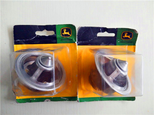
麦克福斯约翰迪尔发动机零配件
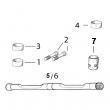
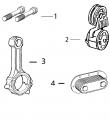
约翰迪尔 4045 4.5T/H 活塞(米) RE527039 排放 2 & 3
|
|
|
发动机和设备型号
|
孔径: 4.19 in 106.5 mm
销径 Ø: 1.6250 in (+/- .0002) = 41mm
发动机型号代码:
4045HE051
4045HL282
4045HL287
4045HL287
4045HT054
4045HT064
4045HT065
4045HT067
4045HT074
4045HT075
4045HDW53
4045HT067
4045HDW54
4045HE050
4045HL280
4045HL281
4045HL282
4045HL283
4045HL284
4045HL287
4045HL288
4045HP052
4045HT054
4045HT056
4045HT059
4045HT061
4045HT064
4045HT065
4045HT072
4045HT086
4045HT087
4045HT281
|
|
|
供应美国约翰.迪尔(强鹿)JOHNDEERE纯正配件。P550758、P550020、P550595、P558329、P550351、P551421、P551423、P556745、P551428、P551422、P551435、P551434、P550192、P550397、P551352、P181054、P77868、P777869、P550667、P550779
强鹿JOHN DEERE柴油机配件、发动机配件、发电机组:
P551345、P608667、P607557、P611856、P611857、P124866、P124867、P551130、P777638、P181099、P772579、P827653、P771548、P771548、P827653、P772579、P772580、P829333、P13194、P550388、C125017、C125004、P772579、C085001、C085002
information&wiring diagrams 20 19 dpsg,ouo1004,671 –19–13sep02–2/2 identification letter type examples s switch switches&push-button, general key switch, light switch, horn switch, flasher switch t transformer ignition coil, ignition transformer u modulator, converter dc transformers v semiconductor, electron tubes transistors, diodes, electron tubes, rectifiers, semiconductors, thyristors, zener diodes w transmission path, conductor, antenna antennas, shielding components, shielded conductors, cable harnesses, conductors, ground conductors x terminal, plug, plug&socket terminal studs, electrical connections, connectors electrical line connection couplers, line connectors, sockets, plugs, terminals, plug-and-socket connections y electrically actuated mechanical device permanent magnets, (solenoid-operated) injection valves, electromagnetic clutches&brakes, air valves, fuel pumps, solenoids, switching valves, start valves, locking systems z electrical filter interference suppression filters ctm67 (24sep02) 20-19 oem engine acces***ies 092402 pn=39 electrical system information&wiring diagrams 20 20 dpsg,ouo1004,672 –19–15mar99–1/1 engine wiring diagram legend—north american series 300, 400, 500&700 engines and early model european (saran) series 300 engines a1 — speed control unit b1 — magnetic speed sen*** b2 — coolant temperature sen*** b3 — oil pressure sen*** f1 — starting circuit fuse (25 amp) f2 — safety switch fuse (14 amp) f3 — tachometer fuse (3 amp) g1 — battery g2 — alternator h1 — coolant temperature indicator lamp h2 — oil pressure indicator lamp h3 — alternator indicator lamp k1 — starter relay k2 — fuel shut-off relay m1 — starter motor p1 — coolant temperature gauge p2 — oil pressure gauge p3 — crankcase oil level switch/gauge p4 — tachometer p5 — hourmeter1 p6 — ammeter r1 — resistor (48 ohm) s1 — key switch s2 — magnetic safety switch—north american auto override module—european (saran) x1 — to meter ground x2 — to y2 fuel shut-off solenoid x3 — — x4 — power to meters x5 — to ignition switch (ign) y1 — starter solenoid y2 — fuel shut-off solenoid 1 on north american series 300 engines without electronic tachometer: early units —a purple wire (shown as a dashed line in wiring diagram) connects between hourmeter “p5”&key switch “s1”. later units&all other north american series 400&500 engines—the wire (shown as a solid line) connects between the hourmeter&magnetic safety switch “s2” (c terminal). ctm67 (24sep02) 20-20 oem engine acces***ies 092402 pn=40 electrical system information&wiring diagrams 20 21 rg,ctm67,g20,2 –19–19nov93–1/1 wiring diagram—north american series 300, 400&500 engines rg9538 –un–08apr99 ctm67 (24sep02) 20-21 oem engine acces***ies 092402 pn=41 electrical system information&wiring diagrams 20 22 rg,ctm67,g20,3 –19–19nov93–1/1 wiring diagram—north american series 700 (8955) engines rg9536 –un–08apr99 ctm67 (24sep02) 20-22 oem engine acces***ies 092402 pn=42 electrical system information&wiring diagrams 20 23 rg,ctm67,g20,4 –19–19nov93–1/1 wiring diagram—european (saran) series 300 engines (early model) rg9535 –un–08apr99 ctm67 (24sep02) 20-23 oem engine acces***ies 092402 pn=43 electrical system information&wiring diagrams 20 24 dpsg,ouo1004,626 –19–09mar99–1/1 engine wiring diagram legend— powertech? 2.9 l, 4.5 l, 6.8 l&8.1 l engines (without ecu) a1 — speed control unit b1 — magnetic speed sen*** b2 — coolant temperature sen*** b3 — oil pressure sen*** f1 — starting circuit fuse (14 amp) f3 — fuse (early models)1 g1 — battery g2 — alternator h1 — coolant temperature indicator lamp h2 — oil pressure indicator lamp h3 — alternator indicator lamp k1 — starter relay k2 — fuel shut-off relay m1 — starter motor p1 — coolant temperature gauge p2 — oil pressure gauge p3 — crankcase oil level switch/gauge p4 — tachometer1 p5 — hourmeter (early models)2 p6 — ammeter r1 — resistor (48 ohm)3 s1 — key switch s2 — magnetic safety switch—north american auto override module—european (saran) w1 — ground on k1 starter relay mounting stud y1 — starter solenoid y2 — fuel shut-off solenoid4 powertech is a registered trademark of deere & company 1 p4 tachometer has a built-in hourmeter. on some earlier engines, a separate hourmeter (p5)&fuse (f3) were used. 2 p4 tachometer has a built-in hourmeter. on some engines, a separate hourmeter (p5)&fuse (f3) are used. 3 later harnesses have two parallel 100 ohm resistors for the alternator. 4 y2 fuel shut-off solenoid shown is for 3-wire in-line fuel injection pump. single connection rotary pumps will have one dark blue wire for power&one black wire for ground. ctm67 (24sep02) 20-24 oem engine acces***ies 092402 pn=44 electrical system information&wiring diagrams 20 25 dpsg,ouo1004,627 –19–09mar99–1/1 engine wiring diagram— powertech? 2.9 l, 4.5 l, 6.8 l&8.1 l engines (without ecu) rg9537 –un–08apr99 powertech is a registered trademark of deere & company ctm67 (24sep02) 20-25 oem engine acces***ies 092402 pn=45 electrical system information&wiring diagrams 20 26 dpsg,ouo1004,731 –19–22mar99–1/1 engine wiring diagram legend— powertech? 10.5 l&12.5 l engines (with lucas ecu)1 f1 — starting circuit fuse (30 amp) g1 — alternator k1 — alternator field relay k2 — starter relay k3 — analog tachometer display m1 — starter motor p1 — coolant temperature gauge p2 — engine oil pressure gauge r1 — resistor 47 ohm s1 — key switch s2 — shut-off switch s3 — tachometer toggle switch powertech is a registered trademark of deere & company 1wiring diagram shown does not show ecu (engine control unit) components. see engine operation&diagnostics manual ctm115 for ecu components&wiring diagrams. ctm67 (24sep02) 20-26 oem engine acces***ies 092402 pn=46 electrical system information&wiring diagrams 20 27 dpsg,ouo1004,732 –19–22mar99–1/1 engine wiring diagram— powertech? 10.5 l&12.5 l engines (with lucas ecu) rg9502 –un–24mar99 powertech is a registered trademark of deere & company ctm67 (24sep02) 20-27 oem engine acces***ies 092402 pn=47 electrical system information&wiring diagrams 20 28 dpsg,ouo1004,864 –19–05may99–1/1 engine wiring diagram— powertech? 8.1 l, 10.5 l&12.5 l engines (with john deere ecu) rg10039 –19–18may99 b1—analog throttle/n2—voltage regulator (for r1—resistor x1—vehicle harness emulator 24v operation) s1—ignition key switch connector e1—back light regulator p1—optional gauge s2—speed select switch x2—alternator harness (24v)/plug (12v) p2—optional gauge (momentary) connector f1—fuse (30 amp) p3—oil pressure gauge s3—bump enable switch x3—single point ground f2—fuse (5 amp) p4—coolant temperature (momentary) x4—can terminator g1—alternator gauge s4—high-low speed switch x5—analog throttle k1—starter relay p5—tachometer display s5—override shutdown connector m1—starter motor p6—hourmeter/diagnostic switch (momentary) n1—transient voltage meter s6—dimmer control or protector jumper plug powertech is a registered trademark of deere & company ctm67 (24sep02) 20-28 oem engine acces***ies 092402 pn=48 electrical system information&wiring diagrams 20 29 dpsg,ouo1004,865 –19–05may99–1/1 engine wiring diagram— powertech? 8.1 l, 10.5 l&12.5 l engines (with john deere ecu) (continued) rg10040 –19–18may99 b1—analog throttle/n2—voltage regulator (for r1—resistor x1—vehicle harness emulator 24v operation) s1—ignition key switch connector e1—back light regulator p1—optional gauge s2—speed select switch x2—alternator harness (24v)/plug (12v) p2—optional gauge (momentary) connector f1—fuse (30 amp) p3—oil pressure gauge s3—bump enable switch x3—single point ground f2—fuse (5 amp) p4—coolant temperature (momentary) x4—can terminator g1—alternator gauge s4—high-low speed switch x5—analog throttle k1—starter relay p5—tachometer display s5—override shutdown connector m1—starter motor p6—hourmeter/diagnostic switch (momentary) n1—transient voltage meter s6—dimmer control or protector jumper plug powertech is a registered trademark of deere & company ctm67 (24sep02) 20-29 oem engine acces***ies 092402 pn=49 electrical system information&wiring diagrams 20 30 dpsg,ouo1004,628 –19–09mar99–1/1 engine wiring diagram legend—saran vdo instrument panel a — 6 mm2, red b — 1.5 mm2, black c — 6 mm2, blue d — 4 mm2, black e — 0.75 mm2, orange f — 0.75 mm2, white g — 0.75 mm2, blue h — 0.75 mm2, purple i — 0.75 mm2, grey j — 0.75 mm2, brown k — 0.75 mm2, dark blue l — 0.75 mm2, black m — 0.75 mm2, green/yellow n — 0.75 mm2, red o—r — not used s — preheater t — battery u — starting motor v — electrical shut-off w — alternator x — oil pressure sen*** y — coolant temperature sen*** z — fuel tank gauge ctm67 (24sep02) 20-30 oem engine acces***ies 092402 pn=50 electrical system information&wiring diagrams 20 31 dpsg,ouo1004,629 –19–09mar99–1/1 engine wiring diagram—saran vdo instrument panel cd623p5 –un–13nov98 ctm67 (24sep02) 20-31 oem engine acces***ies 092402 pn=51 electrical system information&wiring diagrams 20 32 dpsg,ouo1004,779 –19–07apr99–1/1 engine wiring diagram—saran aez instrument panel rg9539 –un–19apr99 a—blue g—blue m—sky blue s—electrical shut-off b—red h—brown n—red t—alternator c—grey i—grey o—fuse (16 amp) u—oil pressure sen*** d—black j—pink p—preheater v—coolant temperature e—orange k—yellow q—battery sen*** f—green l—white r—starting motor w—fuel tank sending unit ctm67 (24sep02) 20-32 oem engine acces***ies 092402 pn=52 group 21 electrical system diagnostics, tests&operation 21 1 dpsg,ouo1004,644 –19–10mar99–1/2 service equipment&tools note: order tools according to information given in the u.s. servicegard? catalog/from the european microfiche tool catalog (mtc). some tools may be available from a local supplier. servicegard is a trademark of deere & company dpsg,ouo1004,644 –19–10mar99–2/2 digital multimeter jt05791 used to make the required measurements in the diagnostic procedures. dpsg,ouo1004,646 –19–10mar99–1/1 electrical system specifications item measurement specification oil pressure gauge switch engines with distributor type pressure closes at 100 kpa (1 bar) (15 psi) injection pump series 400&500 engines&pressure closes at 69 kpa (0.69 bar) (10 psi) 8.1 l engines series 700, 10.5 l&12.5 l pressure closes at 140 kpa (1.4 bar) (20 psi) engines coolant temperature gauge switch temperature contacts close at 104°c (220°f) magnetic safety switch coil approximate current draw 0.7 amps at 12 volts 1.4 amps at 24 volts ctm67 (24sep02) 21-1 oem engine acces***ies 092402 pn=53 electrical system diagnostics, tests&operation 21 2 dpsg,ouo1004,635 –19–10mar99–1/1 general information note: this group covers optional electrical controls and instruments that are available on john deere oem engines. they may be provided by the equipment manufacturer instead of the john deere factory. the following information applies only to those controls&instruments provided by the john deere factory. the electrical system has a negative ground&is either a 12-volt/24-volt system. fuses are strategically placed in the system to protect related circuits&components. note: location&sizes of system fuses vary by application. system fuses: ? 25-amp mdl — located between the ammeter&the key switch. ? 14-amp sfe — located on the magnetic safety switch. ? 3-amp mdx — located between the tachometer and safety switch. ? 3-amp — located between the fuel shut-off&safety switch. ? 5, 14/30-amp — located in fuse holder on front of instrument panel. ? 10-amp — located on control circuit card of saran vdo instrument panel. ? 16-amp — in-line fuse located behind instrument panel on saran aez panel. ctm67 (24sep02) 21-2 oem engine acces***ies 092402 pn=54 electrical system diagnostics, tests&operation 21 3 dpsg,ouo1004,636 –19–13sep02–1/3 component function—instrument panel (without ecu) rg9525 –un–16jun00 a—oil pressure gauge b—coolant temperature gauge c—key switch d—tachometer e—reset safety switch f—fuse holder (14 amp fuse) g—ammeter h—hourmeter i—hand throttle important: any time an electric gauge/meter does not register correctly, replace with a new one. do not attempt to repair it. the instrument panel may consist of the following components: ? hand throttle (if equipped) ? hour meter ? ammeter ? oil pressure gauge ? coolant temperature gauge ? key switch ? safety switch (reset button) ? tachometer ? fuse holder hand throttle note: engines equipped with electronic fuel injection or an electric governor do not use a hand throttle. the hand throttle is used to manually control engine speed. turning the handle, either clockwise or counterclockwise, will lock the throttle position. turn the handle half way between the two lock positions to unlock the throttle. continued on next page ctm67 (24sep02) 21-3 oem engine acces***ies 092402 pn=55 electrical system diagnostics, tests&operation 21 4 dpsg,ouo1004,636 –19–13sep02–2/3 hour meter note: on some instrument panels, the hour meter may be an integral part of the tachometer. the electric hour meter shows the accumulated hours of engine service. the hour meter operates when the engine is operating,/when the reset button is manually held in while the key switch is in the on position. the accumulated hours are displayed in hours&tenths of hours. ammeter the ammeter indicates the rate of charge (+)/discharge (—) of the battery. when the engine is first started, the ammeter will usually indicate a charge rate of approximately 30 amps. after a short period of operation, the ammeter needle will point slightly to the right of “0”, indicating the charging system is operating normally. a problem with the charging system is indicated if the ammeter needle points to the left of “0” during engine operation. oil pressure gauge this gauge indicates engine oil pressure. it also has an adjustable electrical contact which activates the safety switch when oil pressure goes below the pressure set point. this will automatically stop the engine. oil pressure gauge switch—specification engines with distributor type injection pump—pressure closes at 100 kpa (1 bar) (15 psi) series 400&500 engines and 8.1 l engines—pressure closes at 69 kpa (0.69 bar) (10 psi) series 700, 10.5 l&12.5 l engines—pressure closes at 140 kpa (1.4 bar) (20 psi) coolant temperature gauge this gauge indicates coolant temperature. it also has an electrical contact which activates the safety switch when coolant temperature goes above the temperature set point specified below. this will automatically stop the engine. ctm67 (24sep02) 21-4 oem engine acces***ies 092402 pn=56 continued on next page electrical system diagnostics, tests&operation 21 5 dpsg,ouo1004,636 –19–13sep02–3/3 specification coolant temperature gauge switch—temperature. contacts close at 104°c (220°f) key switch the key switch is used to start&stop the engine. a key is required to operate the switch so as to prevent unauthorized operation of the engine. safety switch (reset button) the safety switch de-energizes the fuel shut-off solenoid or rack puller, to stop the engine, if one/more conditions are met: ? low/no oil pressure ? high coolant temperature ? low crankcase oil level (if equipped with engine oil level switch.) ? high crankcase oil level (if equipped with engine oil level switch.) the reset button has to be held when starting the engine. the button allows the safety switch to override the shut-down circuits until safe engine oil pressure is maintained. once engine oil pressure is within specifications, the safety switch will latch&the reset button can be released. tachometer the tachometer indicates engine speed in hundreds of revolutions per minute (rpm). ctm67 (24sep02) 21-5 oem engine acces***ies 092402 pn=57 electrical system diagnostics, tests&operation 21 6 dpsg,ouo1004,733 –19–13sep02–1/2 component function—instrument panel (with lucas ecu) rg9529 –un–24mar99 a—oil pressure gauge b—coolant temperature gauge c—key switch d—shut-off switch e—fuse (30 amp) f—tachometer potentiometer g—throttle switch h—tachometer toggle switch i—tachometer important: any time an electric gauge/meter does not register correctly, replace with a new one. do not attempt to repair it. oil pressure gauge indicates engine oil pressure. coolant temperature gauge indicates engine coolant temperature. key switch the four position key switch controls the engine electrical system. automatic shut-off switch switch will automatically shut off power to engine control unit (ecu) whenever oil pressure drops below/coolant temperature rises above a preset safe operating range. switch also has a shut-off override button that is depressed&held in during engine start-up until oil pressure rises to preset range. fuse holder contains 30 amp fuse. analog throttle potentiometer used to manually adjust engine speeds. throttle switch three position switch that changes between adjustable and preset (slow/fast/rated) engine speeds. tachometer toggle switch three position (momentary) switch used to selectively access the various functions available on the tachometer digital display, by toggling on “select” position. toggle to “reset” position to clear diagnostic trouble codes. ctm67 (24sep02) 21-6 oem engine acces***ies 092402 pn=58 continued on next page electrical system diagnostics, tests&operation 21 7 dpsg,ouo1004,733 –19–13sep02–2/2 analog tachometer with digital display analog tachometer measures engine speed in revolutions per minute (rpm). the digital display on tachometer, when used with tachometer switch (h), is capable of providing engine diagnostic trouble codes, digital engine rpm, battery voltage, coolant temperature&hour meter display. display defaults to hour meter function when selective functions are not requested. key switch the key switch is used to start&stop the engine. a key is required to operate the switch so as to prevent unauthorized operation of the engine. safety switch (reset button) the safety switch de-energizes the fuel shut-off solenoid or rack puller, to stop the engine, if one/more conditions are met: ? low/no oil pressure ? high coolant temperature ? low crankcase oil level (if equipped with engine oil level switch.) ? high crankcase oil level (if equipped with engine oil level switch.) the reset button has to be held when starting the engine. the button allows the safety switch to override the shut-down circuits until safe engine oil pressure is maintained. once engine oil pressure is within specifications, the safety switch will latch&the reset button can be released. tachometer the tachometer indicates engine speed in hundreds of revolutions per minute (rpm). ctm67 (24sep02) 21-7 oem engine acces***ies 092402 pn=59 electrical system diagnostics, tests&operation 21 8 dpsg,ouo1004,866 –19–23may02–1/4 component function—instrument panel (with john deere ecu) rg9547 –un–14aug00 powertech? 4.5 l, 6.8 l tier ii, 8.1 l, 10.5 l, 12.5 l (with deere ecu) panel shown a—engine oil pressure gauge b—amber “warning” indicator c—red “stop engine” indicator d—diagnostic gauge/hour meter e—touch switch f—touch switch g—audible alarm (optional) h—audible alarm override switch (optional) i—throttle control (optional) j—dimmer control (optional) k—engine preheater indicator (optional) l—key start switch m—override shutdown rocker switch (optional) n—idle select rocker switch (optional) o—bump speed enable rocker switch (optional) p—speed select rocker switch (optional) q—fuse holder (5-amp fuse) r—tachometer (optional) s—power meter (percent load) (optional) t—voltmeter (optional) u—engine coolant temperature gauge (optional) this instrument panel for powertech? 8.1 l, 10.5 l and 12.5 l engines was introduced in 1999. it was added for tier ii 4.5 l&6.8 l engines in 2001. the panel is electronically linked to the john deere engine control unit (ecu). this allows the operator to monitor engine performance as well as to diagnose any trouble during engine operation. important: any time an electric gauge/meter does not register correctly, replace with a new one. do not attempt to repair it. all gauges are plug-in type. engine oil pressure gauge the engine oil pressure gauge (a) indicates engine oil pressure in pounds per square inch (psi). amber “warning” indicator the amber “warning” indicator (b) signals an abnormal condition such as low oil pressure, high coolant temperature, water in fuel, low battery voltage, etc. observe displayed code in window of diagnostic gauge (d) for diagnostic trouble code (dtc). ctm67 (24sep02) 21-8 oem engine acces***ies 092402 pn=60 continued on next page electrical system diagnostics, tests&operation 21 9 dpsg,ouo1004,866 –19–23may02–2/4 red “stop engine” indicator the red “stop engine” indicator (c) signals operator to stop engine immediately/as soon as safely possible. a condition exists that could cause damage to engine. diagnostic gauge/hour meter the diagnostic gauge (d) displays diagnostic trouble codes (dtcs) as they occur. other information on the engine can be accessed using the touch switches (e and f). the hour meter shows the operating hours of the engine. normally, the gauge will display engine hours. if a dtc is present, the gauge will alternately flash from hour meter reading to dtcs. (see engine operator’s manual for a list of dtc’s&corresponding engine problems.) touch switches the touch switches are used to change the display on the window of the diagnostic gauge to access engine performance data. pressing the down switch (e)/up switch (f) scrolls through various engine parameters and diagnostic trouble codes. (see engine operator’s manual for instructions.) audible alarm (optional) the audible alarm (g) sounds whenever a low oil pressure, high coolant temperature/water-in-fuel condition exists. audible alarm override switch (optional) the audible alarm override switch (h) can be pressed to silence the alarm for approximately 2-1/2 minutes. throttle control (optional) the throttle control (i) is used to control engine speed. this control is available only on engines with analog throttle. dimmer control (optional) the dimmer control (j) is used to control illumination of the instrument panel. ctm67 (24sep02) 21-9 oem engine acces***ies 092402 pn=61 continued on next page electrical system diagnostics, tests&operation 21 10 dpsg,ouo1004,866 –19–23may02–3/4 rg9547 –un–14aug00 powertech? 4.5 l, 6.8 l tier ii, 8.1 l, 10.5 l, 12.5 l (w/ deere ecu) panel shown engine preheater indicator (optional) the engine preheater indicator (k) lights up while the engine is being preheated for cold weather starting. when the engine is warmed up, the light goes off, indicating the engine can now be started. key start switch the three-position key switch (l) controls the engine electrical system. when the key switch is turned clockwise to “start”, the engine will crank. when the engine starts, the key is released&returns to the “on” (run) position. override shutdown rocker switch (optional) pressing the upper half of the override shutdown switch (m) will override an engine shutdown signal. the switch must be pressed within 30 seconds to prevent undesired shutdown of engine. idle select rocker switch (optional) the idle select switch (n) is used to set the engine at slow idle (turtle)/fast idle (rabbit). bump speed enable rocker switch (optional) pressing upper/lower half of bump speed enable switch (o) allows bump speed to take effect, when activated by speed select switch (p). note: for details on use of bump speed&cruise control options, see engine operation and maintenance manual. speed select rocker switch (optional) the speed select switch (p) is used to bump engine speed up (+)/down (-) in small increments during operation. this switch must be used with the bump speed enable switch (o). fuse holder the fuse holder (q) contains a 5-amp fuse for power to the instrument panel. ctm67 (24sep02) 21-10 oem engine acces***ies 092402 pn=62 continued on next page electrical system diagnostics, tests&operation 21 11 dpsg,ouo1004,866 –19–23may02–4/4 tachometer (optional) the tachometer (r) indicates engine speed in hundreds of revolutions per minute (rpm). power (percent load) meter (optional) the power meter (s) shows percent of available power being used by the engine. voltmeter the voltmeter (t) indicates system battery voltage. the amber “warning” light (b) will illuminate when battery voltage is too low for proper operation of the fuel injection system. engine coolant temperature gauge (optional) the coolant temperature gauge (u) indicates engine coolant temperature in degrees centigrade/fahrenheit. ctm67 (24sep02) 21-11 oem engine acces***ies 092402 pn=63 electrical system diagnostics, tests&operation 21 12 dpsg,ouo1004,637 –19–10mar99–1/2 component function—saran vdo instrument panel cd623p2 –un–19may98 1—oil pressure gauge 3—engine control light 6—coolant temperature light 9—hourmeter 2—coolant temperature 4—oil pressure light 7—fuel level light 10—tachometer gauge 5—battery light 8—key switch 11—preheater light hourmeter the hourmeter is an integral part of the tachometer. it shows the accumulated hours of engine service. the hourmeter operates when the engine is operating and accumulated hours are displayed in hours&tenths of hours. oil pressure gauge the oil pressure gauge indicates engine oil pressure. coolant temperature gauge the coolant temperature gauge indicates coolant temperature. tachometer the tachometer indicates engine speed in hundreds of revolutions per minute (rpm). key switch the four position key switch controls the electrical system. engine control the engine control consists of the following: ? the engine control light (3) illuminates after the engine has started&oil pressure is up to specification. the light indicates that the engine protection circuitry is activated. ctm67 (24sep02) 21-12 oem engine acces***ies 092402 pn=64 continued on next page electrical system diagnostics, tests&operation 21 13 dpsg,ouo1004,637 –19–10mar99–2/2 ? the oil pressure light (4) illuminates when the key switch is turned to the bulb test position (position i). the light will remain on until the engine is started and the specified oil pressure is reached. if oil pressure is lost during engine operation, the light will illuminate&protection circuitry will stop the engine. the oil pressure light will remain on, indicating that the engine was stopped due to a low oil pressure condition. ? the battery light (5) illuminates when the key is turned to the bulb test position (position i). it should go off after approximately five seconds. after the engine is running, if the alternator s*** charging, the light will illuminate&protection circuitry will stop the engine. the battery light will remain on indicating the engine was stopped due to the alternator not charging. ? the coolant temperature light (6) illuminates when the key is turned to the bulb test position (position i). it should go off after approximately five seconds. after the engine is running, if the engine overheats, the light will illuminate&protection circuitry will stop the engine. the coolant temperature light will remain on indicating the engine was stopped due to the engine overheating. ? the fuel level light (7) illuminates when the key is turned to the bulb test position (position i). it should go off after approximately five seconds. after the engine is running, if the engine runs out of fuel, the light will illuminate&protection circuitry will stop the engine. the fuel level light will remain on indicating the engine was stopped due to the fuel tank being empty. ? the preheater light (11) illuminates when the key is turned to the bulb test position (position i). it should go off after approximately five seconds. when the key switch is held in position ii, the engine preheater is energized&the preheater light illuminates. ctm67 (24sep02) 21-13 oem engine acces***ies 092402 pn=65 electrical system diagnostics, tests&operation 21 14 dpsg,ouo1004,777 –19–07apr99–1/2 component function—saran aez instrument panel cd555p5 –un–19aug96 1—oil pressure gauge 3—engine control light 6—coolant temperature light 9—hourmeter 2—coolant temperature 4—oil pressure light 7—fuel level light 10—tachometer gauge 5—alternator light 8—key switch hourmeter the hourmeter shows the accumulated hours of engine service. the hourmeter operates when the engine is operating&accumulated hours are displayed in hours&tenths of hours. oil pressure gauge the oil pressure gauge indicates engine oil pressure. coolant temperature gauge the coolant temperature gauge indicates coolant temperature. tachometer the tachometer indicates engine speed in hundreds of revolutions per minute (rpm). key switch the four position key switch controls the electrical system. the “preheat” position on the switch is for engines equipped with cold weather starting aid. engine control the engine control consists of the following: ? the engine control light (3) illuminates after the engine has started&oil pressure is up to specification. the light indicates that the engine protection circuitry is activated. ctm67 (24sep02) 21-14 oem engine acces***ies 092402 pn=66 continued on next page electrical system diagnostics, tests&operation 21 15 dpsg,ouo1004,777 –19–07apr99–2/2 ? the oil pressure light (4) illuminates when the key switch is turned to the “control” position. the light will remain on until the engine is started&the specified oil pressure is reached. if oil pressure is lost during engine operation, the light will illuminate and protection circuitry will stop the engine. the oil pressure light will remain on, indicating that the engine was stopped due to a low oil pressure condition. ? the alternator light (5) illuminates when the key is turned to the “control” position. it should go off shortly after the engine has started. while the engine is running, if the alternator s*** charging, the light will illuminate&protection circuitry will stop the engine. the alternator light will remain on indicating the engine was stopped due to the alternator not charging. ? after the engine is running, if the engine overheats, the coolant temperature light (6) will illuminate and protection circuitry will stop the engine. the coolant temperature light will remain on indicating the engine was stopped due to the engine overheating. ? after the engine is running, if the engine runs out of fuel, the fuel level light (7) will illuminate and protection circuitry will stop the engine. the fuel level light will remain on indicating the engine was stopped due to the fuel tank being empty. note: engine protection can be tested by connecting sen*** wire to ground. engine should stop and corresponding sen*** light should come on. ctm67 (24sep02) 21-15 oem engine acces***ies 092402 pn=67 electrical system diagnostics, tests&operation 21 16 dpsg,ouo1004,638 –19–10mar99–1/1 component function—crankcase oil level switch/gauge rg6943 –un–01oct93 a—knobs b—oil level switch the oil level switch (b) utilizes a float,&two adjustable pointers that also act as electrical contacts. one pointer is used for low level setpoint&the other for high level setpoint. because it’s metal&grounded through the case, the float provides an electrical path to ground. when the float contacts the adjustable pointers, a path to ground is provided for the magnetic safety switch coil. the completed circuit energizes the coil, which opens the safety switch contacts, stopping the engine. when crankcase oil level drops to the “low” set point, the float will make contact with the pointer&complete the circuit to ground. this activates the safety switch, automatically stopping the engine. also, if coolant gets into the crankcase&increases the oil level to the point where the float contacts the upper set point, the circuit again will be complete&the safety switch will activate, automatically stopping the engine. the high/low set points can be adjusted by turning two knobs (a) located on switch housing. ctm67 (24sep02) 21-16 oem engine acces***ies 092402 pn=68 electrical system diagnostics, tests&operation 21 17 dpsg,ouo1004,639 –19–10mar99–1/1 before you start diagnostics t7199ai –19–17jan90 apply logic when diagnosing any problem. make sure you know exactly what is wrong before making any repairs. always follow the seven basic diagnostic steps: 1. know the system. 2. ask the operator. 3. inspect the system. 4. operate the engine (if possible). 5. list possible causes. 6. reach a conclusion. 7. test the conclusion. an understanding of the following concepts is required when diagnosing the electrical system: ? voltage (volts) ? current (amps) ? resistance (ohms) it is recommended that a digital multimeter (jt05791 or equivalent multimeter with analog display) be used to make the required measurements in the diagnostic procedures. a knowledge of the operation of the particular meter used is assumed. isolate the circuits to be measured by disconnecting the appropriate connectors. turn the key switch to the on or off position as required. ctm67 (24sep02) 21-17 oem engine acces***ies 092402 pn=69 electrical system diagnostics, tests&operation 21 18 dpsg,ouo1004,673 –19–15mar99–1/1 visually inspect electrical system 1. before starting engine. check for: ? bare wires that could ground a component or short across another component ? worn/damaged wire conduit ? loose/broken connectors&wires ? loose/broken alternator belt inspect batteries for: ? corroded terminals ? loose battery terminals/posts ? dirty condition ? cracked case ? proper electrolyte level 2. turn key switch to the on position. check operation of: ? acces***y circuits ? indicator lamps ? gauge lamps look for sparks/smoke which might indicate a short/unwanted ground. if, at this point, the visual inspection does not indicate a malfunction,&the engine can be started, continue to step three. 3. start engine. check for: ? proper operation of gauges ? system charging/discharging ? anything unusual 4. stop engine. after engine has been shut down for five minutes, inspect for overheated components. overheated components will often smell like burned insulation. check if the alternator is hot to the touch. a hot alternator, if engine has run only a short time, is a sure indication there is a problem in the charging system. note: many electrical failures cannot be detected even with the engine operating. a systematic and complete inspection of the electrical system may be necessary. ctm67 (24sep02) 21-18 oem engine acces***ies 092402 pn=70 electrical system diagnostics, tests&operation 21 19 rg,ctm67,g21,8 –19–19nov93–1/2 diagnose electrical system malfunctions symptom problem solution undercharged battery loose/defective alternator belt adjust/replace belt(s) as necessary. (see check&adjust fan&alternator belts in group 40.) excessive engine idle time increase engine rpm when electrical power requirements increase. loose/corroded wire connections clean&tighten connections as on battery, ground strap, starter/necessary. alternator excessive electrical load from added remove acces***ies/install higher acces***ies output alternator. defective regulator test charging system. replace regulator as necessary. defective battery test and/or replace battery. battery uses excessive amounts cracked battery case replace battery. of water charging rate too high test charging system. starter inoperative pto engaged disengage pto. blown fuse replace fuse. (see check fuses in this group.) dead/defective battery test battery&charging system. replace battery as necessary. defective/misadjusted starter replace/adjust safety switch as safety switch necessary. defective starter solenoid/starter repair/replace solenoid/starter as necessary. starter cranks engine slowly undercharged battery test battery&charging system. 泉州南安卡特彼勒323d配件全国发货,日喀则定结县威尔信access4000控制屏纯正配件的批发商,山西晋中榆次TAD940GE空滤欢迎咨询?,日照东港三菱柴油发动机油泵的价格,果洛达日县沃尔沃发电机电磁阀纯正配件的批发商,长春南关perkins发电机p30E1滤清器纯正配件的批发商,北京延庆县卡特320d柴油泵批发,泸州纳溪卡特彼勒C7.1柴油发动机空压机欢迎咨询?,武汉汉阳cat连杆瓦最新报价,山西运城盐湖奥林匹亚GEP100-400KW发电机电器仪表大概的价钱,潍坊诸城帕金斯柴油机水泵报价什么地方有?,延安吴起县P165877唐纳森滤清器价格怎么样?,pe6068tp051 96 (129) 2100 65—79 kpa (0 7—0 8 bar) (9—11 psi) 7410 tractor cd6068tp052 103 (138) 2100 72—88 kpa (0 7—0 9 bar) (10—13 psi) 7420 tractor pe6068tp057 103 (138) 2100 not available 7500 tractor pe6068tp052 103 (138) 2100 72—88 kpa (0 7—0 9 bar) (10—13 psi) 7520 tractor pe6068tp058 115 5 (154) 2100 not available ctm104 (11jul02) 06-210-19 powertech? 4 5 l & 6 8 l diesel engines 071102 pn=621 continued on next page diagnostic specifications dpsg,ouo1004,2748 –19–11jun02–7/24 turbo boost pressures (john deere agricultural equipment) machine model engine model rated power at full load rated turbo boost pressure at full load rated full load rated speed speed speed rpm kpa (bar) (psi) kw (hp) cameco industries (thibodaux, louisiana) sp2252 cane loader pe6068tt850 138 (185) 2400 110—134 kpa (1 1—1 3 bar) (16—19 psi) 100 loader/harvester pe6068tt850 138 (185) 2400 110—134 kpa (1 1—1 3 bar) (16—19 psi) (kanaf) 110t cane tractor pe4045tt851 79 (106) 2200 not available 220 tractor pe6068tt851 138 (185) 2400 110—134 kpa (1 1—1 3 bar) (16—19 psi) 220 4wd tractor/ pe6068tt850 138 (185) 2400 110—134 kpa (1 1—1 3 bar) (16—19 psi) pineapple harvester/ sprayer 404 vegetable sprayer t04045tt850 79 (106) 2200 72—88 kpa (0 7—0 9 bar) (10—13 psi) 06 210 20 continued on next page ctm104 (11jul02) 06-210-20 powertech? 4 5 l & 6 8 l diesel engines 071102 pn=622 diagnostic specifications 06 210 21 dpsg,ouo1004,2748 –19–11jun02–8/24 turbo boost pressures (john deere construction&forestry equipment) machine model engine model rated power at full load rated turbo boost pressure at full load rated full load rated speed speed speed rpm kpa (bar) (psi) kw (hp) davenport, iowa lx80 loader t04045hdw51 85 (114) 2300 not available lx100 loader (hitachi t06068tdw53 103 (138) 2100 62—76 kpa (0 6—0 8 bar) (9—11 psi) construction) pe6068tdw53 103 (138) 2100 62—76 kpa (0 6—0 8 bar) (9—11 psi) lx120 loader (hitachi t06068hdw52 127 (170) 2200 91—111 kpa (0 9—1 1 bar) (13—16 psi) construction) t06068hdw70 127 (170) 2200 91—111 kpa (0 9—1 1 bar) (13—16 psi) pe6068hdw70 127 (170) 2200 91—111 kpa (0 9—1 1 bar) (13—16 psi) tc44h tool carrier t04045tdw50 85 (114) 2200 79—97 kpa (0 8—1 0 bar) (11—14 psi) pe4045tdw50 85 (114) 2200 79—97 kpa (0 8—1 0 bar) (11—14 psi) tc54h tool carrier t06068tdw50 97 (130) 2100 62—83 kpa (0 6—0 8 bar) (9—12 psi) pe6068tdw50 97 (130) 2100 62—83 kpa (0 6—0 8 bar) (9—12 psi) tj460 tc skidder t06068tdw57 127 (170) 2200 91—111 kpa (0 9—1 1 bar) (13—16 psi) pe6068tdw57 127 (170) 2200 91—111 kpa (0 9—1 1 bar) (13—16 psi) tj548 skidder t06068tdw58 95 (127) 2200 not available pe6068tdw58 95 (127) 2200 not available tj648 skidder t06068hdw60 120 (161) 2200 not available pe6068hdw60 120 (161) 2200 not available 344h loader cd4045tf152 73 (98) 2200 50—62 kpa (0 5—0 6 bar) (7—9 psi) 360d skidder t06068tdw54 94 (126) 2200 52—64 kpa (0 5—0 6 bar) (7—9 psi) (timberjack) pe6068tdw54 94 (126) 2200 52—64 kpa (0 5—0 6 bar) (7—9 psi) 444h loader t04045hdw50 97 (130) 2100 not available t04045tdw50 85 (114) 2200 74—90 kpa (0 7—0 9 bar) (10—13 psi) pe4045tdw50 85 (114) 2200 74—90 kpa (0 7—0 9 bar) (10—13 psi) 460 skidder t06068tdw55 95 (127) 2200 not available pe6068tdw55 95 (127) 2200 not available 540/548h skidder t06068tdw54 94 (126) 2200 52—64 kpa (0 5—0 6 bar) (7—9 psi) pe6068tdw54 94 (126) 2200 52—64 kpa (0 5—0 6 bar) (7—9 psi) 540/548g skidder t06068tdw51 94 (126) 2200 52—64 kpa (0 5—0 6 bar) (7—9 psi) (558205— ) 540/548g-ii/548g-iii t06068tdw54 94 (126) 2200 52—64 kpa (0 5—0 6 bar) (7—9 psi) skidder pe6068tdw54 94 (126) 2200 52—64 kpa (0 5—0 6 bar) (7—9 psi) 544/544h loader t06068tdw50 97 (130) 2100 not available pe6068tdw50 97 (130) 2100 not available 624h loader, tc62h t06068hdw50 127 (170) 2200 91—111 kpa (0 9—1 1 bar) (13—16 psi) tool carrier pe6068hdw50 127 (170) 2200 91—111 kpa (0 9—1 1 bar) (13—16 psi) ctm104 (11jul02) 06-210-21 powertech? 4 5 l & 6 8 l diesel engines 071102 pn=623 continued on next page diagnostic specifications 06 210 22 dpsg,ouo1004,2748 –19–11jun02–9/24 turbo boost pressures (john deere construction&forestry equipment) machine model engine model rated power at full load rated turbo boost pressure at full load rated full load rated speed speed speed rpm kpa (bar) (psi) kw (hp) 640/648h skidder t06068tdw55 117 (151) 2200 94—114 kpa (0 9—1 1 bar) (14—17 psi) 640g/648g skidder t06068tdw52 117 (151) 2200 94—114 kpa (0 9—1 1 bar) (14—17 psi) (558325— ) 640/640g-ii skidder t06068tdw55 117 (151) 2200 94—114 kpa (0 9—1 1 bar) (14—17 psi) pe6068tdw55 117 (151) 2200 94—114 kpa (0 9—1 1 bar) (14—17 psi) 648g-iii skidder t06068tdw55 117 (151) 2200 94—114 kpa (0 9—1 1 bar) (14—17 psi) t06068tdw57 127 (170) 2200 91—111 kpa (0 9—1 1 bar) (13—16 psi) pe6068tdw57 127 (170) 2200 91—111 kpa (0 9—1 1 bar) (13—16 psi) 670c grader t06068hdw53 112 (150) 2000 94—114 kpa (0 9—1 1 bar) (14—17 psi) pe6068hdw53 112 (150) 2000 94—114 kpa (0 9—1 1 bar) (14—17 psi) 670c series ii grader t06068hdw53 112 (150) 2000 94—114 kpa (0 9—1 1 bar) (14—17 psi) pe6068hdw53 112 (150) 2000 94—114 kpa (0 9—1 1 bar) (14—17 psi) 670ch grader t06068hdw55 127 (170) 2000 105—125 kpa (1 1—1 3 bar) (15—18 psi) pe6068hdw55 127 (170) 2000 105—125 kpa (1 1—1 3 bar) (15—18 psi) t06068hdw58 130 (174) 2200 96—118 kpa (0 9—1 2 bar) (14—17 psi) pe6068hdw58 130 (174) 2200 96—118 kpa (0 9—1 2 bar) (14—17 psi) 670ch series ii grader t06068hdw58 130 (174) 2200 96—118 kpa (0 9—1 2 bar) (14—17 psi) pe6068hdw58 130 (174) 2200 96—118 kpa (0 9—1 2 bar) (14—17 psi) 672ch grader t06068hdw55 127 (170) 2000 105—125 kpa (1 1—1 3 bar) (15—18 psi) pe6068hdw55 127 (170) 2000 105—125 kpa (1 1—1 3 bar) (15—18 psi) 672ch series ii grader t06068hdw58 130 (174) 2200 96—118 kpa (0 9—1 2 bar) (14—17 psi) pe6068hdw58 130 (174) 2200 96—118 kpa (0 9—1 2 bar) (14—17 psi) 690e lc excavator t06068tdw56 107 (143) 2100 62—76 kpa (0 6—0 8 bar) (9—11 psi) (559603— ) dubuque, iowa dx75 hst crawler dozer t04045tt070 60 (80) 2200 45—55 kpa (0 5—0 6 bar) (6—8 psi) (japan) pe4045tt070 60 (80) 2200 45—55 kpa (0 5—0 6 bar) (6—8 psi) hyex military excavator pe4045tt050 86 (115) 2500 97—119 kpa (0 9—1 2 bar) (14—17 psi) 120/120c excavator t04045tt052 69 (93) 2100 63—77 kpa (0 6—0 8 bar) (9—11 psi) 210le landscape loader t04045dt050 54 (73) 2100 not available pe4045dt050 54 (73) 2100 not available 230c excavator pe6068ht054 134 (180) 2100 74—90 kpa (0 7—0 9 bar) (10—13 psi) 270c excavator pe6068ht055 141 (189) 2150 82—100 kpa (0 9—1 0 bar) (11—14 psi) 310e backhoe loader t04045tt056 58 (78) 2200 44—54 kpa (0 4—0 5 bar) (6—8 psi) (alt comp) 310g backhoe loader t04045tt058 60 (80) 2200 not available (xxxxxx— ) (tier ii) ctm104 (11jul02) 06-210-22 powertech? 4 5 l & 6 8 l diesel engines 071102 pn=624 continued on next page diagnostic specifications 06 210 23 dpsg,ouo1004,2748 –19–11jun02–10/24 turbo boost pressures (john deere construction&forestry equipment) machine model engine model rated power at full load rated turbo boost pressure at full load rated full load rated speed speed speed rpm kpa (bar) (psi) kw (hp) 310g backhoe loader t04045tt080 63 (84) 2200 45—55 kpa (0 5—0 6 bar) (6—8 psi) (alt comp) ( —xxxxxx) (tier i) pe4045tt080 63 (84) 2200 45—55 kpa (0 5—0 6 bar) (6—8 psi) (tier i) 310g backhoe loader t04045tt088 63 (84) 2200 78—96 kpa (0 8—1 0 bar) (12—14 psi) (alt comp) (xxxxxx— ) (tier ii) pe4045tt088 63 (84) 2200 78—96 kpa (0 8—1 0 bar) (12—14 psi) (tier ii) 310se backhoe loader t04045tt050 66 (89) 2200 56—68 kpa (0 6—0 7 bar) (8—10 psi) 310sg backhoe loader t04045tt081 66 (89) 2200 56—68 kpa (0 5—0 7 bar) (8—10 psi) ( —xxxxxx) (tier i) pe4045tt081 66 (89) 2200 56—68 kpa (0 5—0 7 bar) (8—10 psi) (tier i) 310sg backhoe loader t04045tt089 69 (93) 2300 67—83 kpa (0 7—0 8 bar) (10—12 psi) (xxxxxx— ) (tier ii) pe4045tt089 69 (93) 2300 67—83 kpa (0 7—0 8 bar) (10—12 psi) (tier ii) 315se backhoe loader t04045tt060 66 (89) 2200 56—68 kpa (0 6—0 7 bar) (8—10 psi) 315sg backhoe loader t04045tt081 66 (89) 2200 56—68 kpa (0 6—0 7 bar) (8—10 psi) (side—shift) ( —xxxxxx) (tier i) 315sg backhoe loader t04045tt089 69 (93) 2300 67—83 kpa (0 7—0 8 bar) (10—12 psi) (side—shift) (xxxxxx— ) (tier ii) pe4045tt089 69 (93) 2300 67—83 kpa (0 7—0 8 bar) (10—12 psi) (tier ii) 324h loader cd4045tf153 60 (80) 2200 not available 344h loader t04045tf152 73 (98) 2200 not available cd4045tf152 73 (98) 2200 not available 390 excavator t04045tt054 63 (89) 2200 50—62 kpa (0 5—0 6 bar) (7—9 psi) 410e backhoe loader t04045tt053 73 (98) 2200 66—80 kpa (0 7—0 8 bar) (10—12 psi) 410g backhoe loader t04045tt082 73 (98) 2200 66—80 kpa (0 7—0 8 bar) (10—12 psi) pe4045tt082 73 (98) 2200 66—80 kpa (0 7—0 8 bar) (10—12 psi) 450g/450gtc crawler t04045tt061 58 (78) 2100 38—47 kpa (0 4—0 5 bar) (6—7 psi) dozer pe4045tt061 58 (78) 2100 38—47 kpa (0 4—0 5 bar) (6—7 psi) 450gtc series iv t04045tt067 58 (78) 2100 38—47 kpa (0 4—0 5 bar) (6—7 psi) crawler dozer (840461— ) pe4045tt067 58 (78) 2100 38—47 kpa (0 4—0 5 bar) (6—7 psi) 450h lgp crawler dozer t04045tt058 60 (80) 2200 49—59 kpa (0 5—0 6 bar) (7—9 psi) ( —xxxxxx) (tier i) pe4045tt058 60 (80) 2200 49—59 kpa (0 5—0 6 bar) (7—9 psi) (tier i) ctm104 (11jul02) 06-210-23 powertech? 4 5 l & 6 8 l diesel engines 071102 pn=625 continued on next page diagnostic specifications 06 210 24 dpsg,ouo1004,2748 –19–11jun02–11/24 turbo boost pressures (john deere construction&forestry equipment) machine model engine model rated power at full load rated turbo boost pressure at full load rated full load rated speed speed speed rpm kpa (bar) (psi) kw (hp) 450h lgp crawler dozer t04045tt085 60 (80) 2200 51—63 kpa (0 5—0 6 bar) (7—9 psi) (xxxxxx— ) (tier ii) pe4045tt085 60 (80) 2200 51—63 kpa (0 5—0 6 bar) (7—9 psi) (tier ii) 450h crawler dozer t04045tt057 56 (75) 2200 41—51 kpa (0 4—0 5 bar) (7—8 psi) (alt comp) ( —xxxxxx) (tier i) pe4045tt057 56 (75) 2200 41—51 kpa (0 4—0 5 bar) (7—8 psi) (tier i) 450h crawler dozer pe4045tt084 56 (75) 2200 46—56 kpa (0 5—0 6 bar) (7—9 psi) (alt comp) (xxxxxx— ) (tier ii) t04045tt084 56 (75) 2200 46—56 kpa (0 5—0 6 bar) (7—9 psi) (tier ii) 455 g series iv crawler t04045tt061 58 (78) 2100 38—47 kpa (0 4—0 5 bar) (6—7 psi) loader (840461— ) pe4045tt061 58 (78) 2100 38—47 kpa (0 4—0 5 bar) (6—7 psi) 455gtc crawler loader t04045tt067 58 (78) 2100 38—47 kpa (0 4—0 5 bar) (6—7 psi) pe4045tt067 58 (78) 2100 38—47 kpa (0 4—0 5 bar) (6—7 psi) 485e/486e/488e forklift t04045dt050 54 (73) 2100 not available pe4045dt050 54 (73) 2100 not available 550g crawler dozer t04045tt062 66 (89) 2100 51—63 kpa (0 5—0 6 bar) (7—9 psi) (840461— ) 550gtc crawler dozer t04045tt062 66 (89) 2100 51—63 kpa (0 5—0 6 bar) (7—9 psi) (840461— ) pe4045tt068 66 (89) 2100 51—63 kpa (0 5—0 6 bar) (7—9 psi) 550h crawler dozer t04045tt064 63 (84) 2200 42—52 kpa (0 4—0 5 bar) (6—7 psi) ( —xxxxxx) (tier i) pe4045tt064 63 (84) 2200 42—52 kpa (0 4—0 5 bar) (6—7 psi) (tier i) 550h crawler dozer t04045tt087 66 (89) 2200 56—68 kpa (0 5—0 7 bar) (8—10 psi) (xxxxxx— ) (tier ii) pe4045tt087 66 (89) 2200 56—68 kpa (0 5—0 7 bar) (8—10 psi) (tier ii) 550h lgp crawler dozer t04045tt065 66 (89) 2200 42—52 kpa (0 4—0 5 bar) (6—7 psi) ( —xxxxxx) (tier i) pe4045tt065 66 (89) 2200 42—52 kpa (0 4—0 5 bar) (6—7 psi) (tier i) 550h lgp crawler dozer t04045tt086 63 (84) 2200 50—62 kpa (0 5—0 6 bar) (7—9 psi) (xxxxxx— ) (tier ii) pe4045tt086 63 (84) 2200 50—62 kpa (0 5—0 6 bar) (7—9 psi) (tier ii) 555g crawler loader t04045tt063 67 1 (90) 2100 63—77 kpa (0 6—0 8 bar) (9—11 psi) (840461— ) pe4045tt063 67 1 (90) 2100 63—77 kpa (0 6—0 8 bar) (9—11 psi) ctm104 (11jul02) 06-210-24 powertech? 4 5 l & 6 8 l diesel engines 071102 pn=626 continued on next page diagnostic specifications 06 210 25 dpsg,ouo1004,2748 –19–11jun02–12/24 turbo boost pressures (john deere construction&forestry equipment) machine model engine model rated power at full load rated turbo boost pressure at full load rated full load rated speed speed speed rpm kpa (bar) (psi) kw (hp) 555gtc crawler loader t04045tt069 74 (99) 2100 63—77 kpa (0 6—0 8 bar) (9—11 psi) pe4045tt069 74 (99) 2100 63—77 kpa (0 6—0 8 bar) (9—11 psi) 643g feller buncher t06068tt053 120 (161) 2200 90—110 kpa (0 9—1 1 bar) (13—16 psi) pe6068tt053 120 (161) 2200 90—110 kpa (0 9—1 1 bar) (13—16 psi) 643h feller buncher pe6068tt058 120 (161) 2200 90—110 kpa (0 9—1 1 bar) (13—16 psi) 650g crawler dozer t04045tt063 74 (99) 2100 63—77 kpa (0 6—0 8 bar) (9—11 psi) pe4045tt063 74 (99) 2100 63—77 kpa (0 6—0 8 bar) (9—11 psi) 650gtc crawler dozer t04045tt069 74 (99) 2100 63—77 kpa (0 6—0 8 bar) (9—11 psi) pe4045tt069 74 (99) 2100 63—77 kpa (0 6—0 8 bar) (9—11 psi) 650h crawler dozer t04045tt066 73 (98) 2200 51—62 kpa (0 5—0 7 bar) (7—9 psi) pe4045tt066 73 (98) 2200 51—62 kpa (0 5—0 7 bar) (7—9 psi) 650h forest fire plow t04045tt083 73 (98) 2200 51—62 kpa (0 5—0 7 bar) (7—9 psi) t04045tt091 85 (114) 2200 not available pe4045tt091 85 (114) 2200 not available 653e feller buncher t06068tt053 120 (161) 2200 90—110 kpa (0 9—1 1 bar) (13—16 psi) pe6068tt053 120 (161) 2200 90—110 kpa (0 9—1 1 bar) (13—16 psi) 653g feller buncher t06068tt053 120 (161) 2200 90—110 kpa (0 9—1 1 bar) (13—16 psi) (120 kw) pe6068tt053 120 (161) 2200 90—110 kpa (0 9—1 1 bar) (13—16 psi) pe6068tt059 120 (161) 2200 90—110 kpa (0 9—1 1 bar) (13—16 psi) 653g feller buncher pe6068ht057 140 (188) 2200 90—110 kpa (0 9—1 1 bar) (13—16 psi) (140 kw) 690 excavator t06068tt051 110 (148) 2100 72—88 kpa (0 7—0 9 bar) (10—13 psi) pe6068tt051 110 (148) 2100 72—88 kpa (0 7—0 9 bar) (10—13 psi) 700h crawler dozer t06068tt056 92 (123) 2100 46—56 kpa (0 5—0 6 bar) (7—9 psi) pe6068tt056 92 (123) 2100 46—56 kpa (0 5—0 6 bar) (7—9 psi) 710d/710e backhoe t06068tt050 92 (123) 2200 53—65 kpa (0 5—0 7 bar) (8—9 psi) loader (—834729) pe6068tt050 92 (123) 2200 53—65 kpa (0 5—0 7 bar) (8—9 psi) 710d backhoe loader t06068tt055 92 (123) 2200 53—65 kpa (0 5—0 7 bar) (8—9 psi) (834730— ) pe6068tt055 92 (123) 2200 53—65 kpa (0 5—0 7 bar) (8—9 psi) 710g backhoe loader t06068tt057 96 (129) 2200 79—97 kpa (0 8—1 0 bar) (12—14 psi) (tier ii) pe6068tt057 96 (129) 2200 79—97 kpa (0 8—1 0 bar) (12—14 psi) (tier ii) 750c crawler dozer t06068tt052 110 (148) 2100 72—88 kpa (0 7—0 9 bar) (11—13 psi) (831372— ) pe6068tt052 110 (148) 2100 72—88 kpa (0 7—0 9 bar) (11—13 psi) 843g feller buncher t06068ht050 140 (188) 2200 90—110 kpa (0 9—1 1 bar) (13—16 psi) pe6068ht050 140 (188) 2200 90—110 kpa (0 9—1 1 bar) (13—16 psi) ctm104 (11jul02) 06-210-25 powertech? 4 5 l & 6 8 l diesel engines 071102 pn=627 continued on next page diagnostic specifications 06 210 26 dpsg,ouo1004,2748 –19–11jun02–13/24 turbo boost pressures (john deere construction&forestry equipment) machine model engine model rated power at full load rated turbo boost pressure at full load rated full load rated speed speed speed rpm kpa (bar) (psi) kw (hp) 843h feller buncher pe6068ht056 140 (188) 2200 90—110 kpa (0 9—1 1 bar) (13—16 psi) 850h crawler pe6068ht058 135 (181) 2100 not available knoxville, tennessee/dubuque, iowa jd7 skid steer loader pe4045dkv50 not available not available not available 280 skid steer loader pe4045tkv50 66 5 (89) 2400 62—76 kpa (0 6—0 8 bar) (9—11 psi) pe4045tkv51 66 5 (89) 2400 62—76 kpa (0 6—0 8 bar) (9—11 psi) saltillo, mexico 110 excavator t04045tt054 63 (84) 2200 50—62 kpa (0 5—0 6 bar) (7—9 psi) pe4045tp052 63 (84) 2200 50—62 kpa (0 5—0 6 bar) (7—9 psi) 120 excavator t04045tt052 69 (93) 2200 63—77 kpa (0 6—0 8 bar) (9—11 psi) pe4045tp051 69 (93) 2200 63—77 kpa (0 6—0 8 bar) (9—11 psi) 120c excavator pe4045hp050 70 (94) 2200 55—67 kpa (0 5—0 7 bar) (8—10 psi) (tier ii) 160c lc excavator pe4045hp051 85 (114) 2300 85—103 kpa (0 9—1 0 bar) (12—15 psi) (tier ii) 160lc excavator t04045tt055 81 (109) 2300 89—109 kpa (0 9—1 1 bar) (13—16 psi) pe4045tp053 81 (109) 2300 89—109 kpa (0 9—1 1 bar) (13—16 psi) deere-hitachi (north carolina, canada) 200c lc excavator pe6068ht053 110 (148) 2150 72—88 kpa (0 7—0 9 bar) (11—13 psi) (tier ii) 200lc excavator t06068tt051 110 (148) 2150 69—85 kpa (0 7—0 8 bar) (10—12 psi) pe6068tt051 110 (148) 2150 69—85 kpa (0 7—0 8 bar) (10—12 psi) 230c lc excavator pe6068ht054 134 (180) 2100 99—121 kpa (1 0—1 2 bar) (15—17 psi) 270lc excavator pe6068ht052 141 (189) 2150 not available 2054 logger pe6068tt053 110 (148) 2150 not available 2554 logger pe6068ht054 134 (180) 2100 not available timberjack (deere) (sweden/finland/canada) 330/335/430/435/535 pe6068ttj50 120 (161) 2200 89—109 kpa (0 9—1 1 bar) (13—15 psi) knuckleboom log loader 770 wheel harvester cd4045htj077 86 (115) 2000 not available 810 forwarder cd4045htj075 86 (115) 2000 not available 1010 forwarder cd4045htj076 86 (115) 2000 not available pe4045htj50 not available not available not available 1070 wheel harvester cd6068htj076 129 (173) 2000 not available 1110 forwarder cd6068htj075 129 (173) 2000 not available pe6068htj52 not available not available not available 1410 forwarder cd6068htj077 129 (173) 2000 not available hitachi construction machinery (tsuchiura, japan) ctm104 (11jul02) 06-210-26 powertech? 4 5 l & 6 8 l diesel engines 071102 pn=628 continued on next page diagnostic specifications 06 210 27 dpsg,ouo1004,2748 –19–11jun02–14/24 turbo boost pressures (john deere construction&forestry equipment) machine model engine model rated power at full load rated turbo boost pressure at full load rated full load rated speed speed speed rpm kpa (bar) (psi) kw (hp) 270c lc excavator pe6068ht055 141 (189) 2150 108—132 kpa (1 1—1 3 bar) (16—19 psi) (tier ii) 270lc excavator t06068ht052 141 (189) 2150 82—100 kpa (0 9—1 0 bar) (12—14 psi) pe6068ht052 141 (189) 2150 82—100 kpa (0 9—1 0 bar) (12—14 psi) turbo boost pressures (john deere commercial&consumer equipment) machine model engine model rated power at full load rated turbo boost pressure at full load rated full load rated speed speed speed rpm kpa (bar) (psi) kw (hp) augusta, georgia 5510/5510n tractor cd4045tlv50 56 (75) pto 2400 54—66 kpa (0 5—0 7 bar) (8—10 psi) pe4045tlv50 56 (75) pto 2400 54—66 kpa (0 5—0 7 bar) (8—10 psi) 5510/5510n tractor (no pe4045tlv51 67 (90) 2400 56—66 kpa (0 6—0 7 bar) (8—10 psi) air heater option) 5520/5520n tractor pe4045tlv50 56 (75) 2400 54—66 kpa (0 5—0 7 bar) (8—10 psi) 5520/5520n tractor (no pe4045tlv51 66 5 (89) 2400 56—66 kpa (0 6—0 7 bar) (8—10 psi) air heater option) agritalia srl (vittoria, sicily, italy) 5510 tractor (agritalia) cd4045tat50 61 (81) 2300 65—79 kpa (0 7—0 8 bar) (9—11 psi) continued on next page ctm104 (11jul02) 06-210-27 powertech? 4 5 l & 6 8 l diesel engines 071102 pn=629 diagnostic specifications 06 210 28 dpsg,ouo1004,2748 –19–11jun02–15/24 turbo boost pressures (john deere oem/outside equipment manufacturers) engine model fuel injection replacement rated full load turbo boost pressure at full load rated (emission system pump part injection power at rated speed certification) option no pump full load speed kpa (bar) (psi) code rated rpm speed kw (hp) 4045tf120 16mt re503733 70 (94) 1500 63—77 kpa (0 6—0 8 bar) (9—11 psi) (non—certified) 16mu re505050 70 (94) 1500 63—77 kpa (0 6—0 8 bar) (9—11 psi) 4045tf150 1605 re61668 re69781 86 (115) 2500 97—119 kpa (1 0—1 2 bar) (14—17 psi) (tier i) 1605 re69781 86 (115) 2500 97—119 kpa (1 0—1 2 bar) (14—17 psi) 1606 re64133 93 (125) 2400 109—133 kpa (1 1—1 3 bar) (16—19 psi) 1656 re63610 re67562 75 (100) 1800 65—79 kpa (0 7—0 8 bar) (9—12 psi) 1656 re67562 75 (100) 1800 65—79 kpa (0 7—0 8 bar) (9—12 psi) 1675 re60091 re69782 86 (115) 2500 96—118 kpa (1 0—1 2 bar) (14—18 psi) 1675 re69782 86 (115) 2500 96—118 kpa (1 0—1 2 bar) (14—18 psi) 1676 re60093 re61668 86 (115) 2500 91—119 kpa (0 9—1 1 bar) (13—17 psi) 1677 re60096 re67653 75 (100) 1800 65—79 kpa (0 7—0 8 bar) (9—12 psi) 1677 re67563 75 (100) 1800 65—79 kpa (0 7—0 8 bar) (9—12 psi) 1692 re61668 re500881 86 (115) 2500 97—119 kpa (1 0—1 2 bar) (14—17 psi) 1692 re500881 re502416 86 (115) 2500 97—119 kpa (1 0—1 2 bar) (14—17 psi) 1692 re502416 86 (115) 2500 97—119 kpa (1 0—1 2 bar) (14—17 psi) 1694 re67863 re69779 74 (99) 2500 81—99 kpa (0 8—1 0 bar) (12—14 psi) 1694 re69779 74 (99) 2500 81—99 kpa (0 8—1 0 bar) (12—14 psi) 1695 re69739 re69780 74 (99) 2500 81—99 kpa (0 8—1 0 bar) (12—14 psi) 1695 re69780 74 (99) 2500 81—99 kpa (0 8—1 0 bar) (12—14 psi) 16ab re69779 75 (100) 2500 81—99 kpa (0 8—1 0 bar) (12—14 psi) 16bf re500848 73 (98) 2200 66—80 kpa (0 7—0 8 bar) (10—12 psi) 16ce re501180 74 (99) 2500 81—99 kpa (0 8—1 0 bar) (12—14 psi) 16cm re501365 66 5 (89) 2200 56—68 kpa (0 6—0 7 bar) (8—10 psi) 16gl re502706 78 (105) 2300 80—94 kpa (0 8—0 9 bar) (12—14 psi) 16lp re67562 75 (101) 1800 65—79 kpa (0 7—0 8 bar) (9—11 psi) 16lz re503735 82 (110) 1800 85—99 kpa (0 9—1 0 bar) (12—14 psi) 16ma re504696 re504931 82 (110) 1800 85—99 kpa (0 9—1 0 bar) (12—14 psi) 16ma re504931 82 (110) 1800 85—99 kpa (0 9—1 0 bar) (12—14 psi) 16mt re503733 re505050 70 (94) 1500 63—77 kpa (0 6—0 8 bar) (9—11 psi) 16mt re505050 70 (94) 1500 63—77 kpa (0 6—0 8 bar) (9—11 psi) 16mu re504695 re505050 70 (94) 1500 63—77 kpa (0 6—0 8 bar) (9—11 psi) 16mu re505050 70 (94) 1500 63—77 kpa (0 6—0 8 bar) (9—11 psi) 4045tf151 1677 re67563 75 (101) 1800 65—79 kpa (0 7—0 8 bar) (9—11 psi) (tier i) 16cu re501192 80 (107) 2200 68—82 kpa (0 7—0 8 bar) (10—12 psi) 16nh re505411 75 (101) 1800 65—79kpa (0 7—0 8 bar) (9—11 psi) 4045tf152 16ax re500551 76 (102) 2400 75—91 kpa (0 8— 09 bar) (11—13 psi) (tier i) ctm104 (11jul02) 06-210-28 powertech? 4 5 l & 6 8 l diesel engines 071102 pn=630 continued on next page diagnostic specifications 06 210 29 dpsg,ouo1004,2748 –19–11jun02–16/24 turbo boost pressures (john deere oem/outside equipment manufacturers) engine model fuel injection replacement rated full load turbo boost pressure at full load rated (emission system pump part injection power at rated speed certification) option no pump full load speed kpa (bar) (psi) code rated rpm speed kw (hp) 4045tf154 1605 re69781 86 (115) 2500 97—119 kpa (1 0—1 2 bar) (14—17 psi) (tier i) 4045tf155 16ax re500551 76 (102) 2400 75—91 kpa (0 8—0 9 bar) (11—13 psi) (tier i) 16jt re500551 76) 102) 2400 75—91 kpa (0 8—0 9 bar) (11—13 psi) 4045tf157 16gq re503048 83 (111) 1500 102—116 kpa (1 0—1 2 bar) (15—17 psi) (tier i) 16lv re503830 83 (111) 1500 102—116 kpa (1 0—1 2 bar) (15—17 psi) 4045tf158 16gq re503048 83 (111) 1500 102—116 kpa (1 0—1 2 bar) (15—17 psi) (tier i) 16lz re503735 82 (110) 1800 85—99 kpa (0 9—1 0 bar) (12—14 psi) 16ma re504696 82 (110) 1800 85—99 kpa (0 9—1 0 bar) (12—14 psi) 16mt re503733 70 (94) 1500 63—77 kpa (0 6—0 8 bar) (9—11 psi) 16mu re504695 re505050 70 (94) 1500 63—77 kpa (0 6—0 8 bar) (9—11 psi) 16mu re505050 70 (94) 1500 63—77 kpa (0 6—0 8 bar) (9—11 psi) 4045tf161 16pz re500848 73 (98) 2200 not available (non—certified) 4045tf162 16tg re507941 77 (103) 2000 not available (non—certified) 4045tf220 16gq re503048 83 (111) 1500 102—116 kpa (1 0—1 2 bar) (15—17 psi) (non—certified) 16lv re503830 83 (111) 1500 102—116 kpa (1 0—1 2 bar) (15—17 psi) 16mt re503733 70 (94) 1500 63—77 kpa (0 6—0 8 bar) (9—11 psi) 16mv re503736 100 (134) 1800 117—131 kpa (1 2—1 3 bar) (17—19 psi) 16mw re504682 100 (134) 1800 117—131 kpa (1 2—1 3 bar) (17—19 psi) 16nt re504465 86 (115) 2500 86—100 kpa (0 9—1 0 bar) (12—15 psi) 16nu re504466 86 (115) 2500 86—100 kpa (0 9—1 0 bar) (12—15 psi) 4045tf250 1606 re64133 93 (125) 2400 109—133 kpa (1 1—1 3 bar) (16—19 psi) (tier i) 1608 re67564 84 (113) 1800 82—100 kpa (0 8—1 0 bar) (12—15 psi) 1667 re59968 93 (125) 2400 109—133 kpa (1 1—1 3 bar) (16—19 psi) 1682 re67566 84 (113) 1800 82—100 kpa (0 8—1 0 bar) (12—15 psi) 1683 re60124 93 (125) 2400 109—133 kpa (1 1—1 3 bar) (16—19 psi) 160r re70941 84 (113) 1800 82—100 kpa (0 8—1 0 bar) (12—15 psi) 16cv re501346 85 (114) 2200 79—97 kpa (0 8—1 0 bar) (12—14 psi) 16gq re503048 83 (111) 1500 102—116 kpa (1 0—1 2 bar) (15—17 psi) 16lq re67564 84 (113) 1800 82—100 kpa (0 8—1 0 bar) (12—15 psi) 16lv re503830 83 (111) 1500 102—116 kpa (1 0—1 2 bar) (15—17 psi) 16mb re503737 91 (122) 1800 104—118 kpa (1 0—1 2 bar) (15—17 psi) 16mc re504932 91 (122) 1800 104—118 kpa (1 0—1 2 bar) (15—17 psi) 161c re507525 100 (134) 1800 116—142 kpa (1 2—1 4 bar) (17—20 psi) 161d re507526 100 (134) 1800 116—142 kpa (1 2—1 4 bar) (17—20 psi) ctm104 (11jul02) 06-210-29 powertech? 4 5 l & 6 8 l diesel engines 071102 pn=631 continued on next page diagnostic specifications 06 210 30 dpsg,ouo1004,2748 –19–11jun02–17/24 turbo boost pressures (john deere oem/outside equipment manufacturers) engine model fuel injection replacement rated full load turbo boost pressure at full load rated (emission system pump part injection power at rated speed certification) option no pump full load speed kpa (bar) (psi) code rated rpm speed kw (hp) 4045tf251 1606 re64133 93 (125) 2400 109—133 kpa (1 1—1 3 bar) (16—19 psi) (tier i) 4045tf252 85 (114) 2350 81—99 kpa (0 8—1 0 bar) (12—14 psi) (tier i) 4045tf253 16te re507257 85 (114) 2400 88—108 kpa (0 9—1 0 bar) (12—15 psi) (tier i) 4045tf257 16gq re503048 83 (111) 1500 102—116 kpa (1 0—1 2 bar) (15—17 psi) (tier i) 16lv re503830 83 (111) 1500 102—116 kpa (1 0—1 2 bar) (15—17 psi) 4045tf258 16gq re503048 83 (111) 1500 102—116 kpa (1 0—1 2 bar) (15—17 psi) (tier i) 16lv re503830 83 (111) 1500 102—116 kpa (1 0—1 2 bar) (15—17 psi) 16mb re503737 91 (122) 1800 104—118 kpa (1 0—1 2 bar) (15—17 psi) 16mc re504932 91 (122) 1800 104—118 kpa (1 0—1 2 bar) (15—17 psi) 16mv re503736 100 (134) 1800 117—131 kpa (1 2—1 3 bar) (17—19 psi) 16mw re504682 100 (134) 1800 117—131 kpa (1 2—1 3 bar) (17—19 psi) 4045tf275 7288 (12v) re515464 71 (95) 2000 not available (tier ii) 7289 (24v) re515464 71 (95) 2000 not available 161k, 163h re515464 74 (99) 1800 not available (12v) 161l, 163l re515464 74 (99) 1800 not available (24v) 161k, 163h re515464 74 (99) 2200 not available (12v) 161l, 163l re515464 74 (99) 2200 not available (24v) 161k, 163h re515464 74 (99) 2500 not available (12v) 161l, 163l re515464 74 (99) 2500 not available (24v) 7290 (12v) re515464 82 (110) 2400 93—113 kpa (0 9—1 1 bar) (14—16 psi) 7291 (24v) re515464 82 (110) 2400 93—113 kpa (0 9—1 1 bar) (14—16 psi) 7292 (12v) 84 (113) 1800 not available 7293 (24v) 84 (113) 1800 not available 7288, 163h re515464 86 (115) 2500 90—110 kpa (0 9—1 1 bar) (14—16 psi) (12v) 7289, 163l re515464 86 (115) 2500 90—110 kpa (0 9—1 1 bar) (14—16 psi) (24v) 4045tfm50 16hm re503163 73 (98) 1800 45—57 kpa (0 4—0 6 bar) (7—9 psi) (non—certified marine) ctm104 (11jul02) 06-210-30 powertech? 4 5 l & 6 8 l diesel engines 071102 pn=632 continued on next page diagnostic specifications 06 210 31 dpsg,ouo1004,2748 –19–11jun02–18/24 turbo boost pressures (john deere oem/outside equipment manufacturers) engine model fuel injection replacement rated full load turbo boost pressure at full load rated (emission system pump part injection power at rated speed certification) option no pump full load speed kpa (bar) (psi) code rated rpm speed kw (hp) 16hn re503162 73 (98) 1800 47—57 kpa (0 5—0 6 bar) (7—9 psi) 16hp re503861 101 (135) 2500 95—117 kpa (1 0—1 2 bar) (14—17 psi) 16hq re503860 101 (135) 2500 95—117 kpa (1 0—1 2 bar) (14—17 psi) 16lk re503160 111 (149) 2600 128—156 kpa (1 3—1 6 bar) (19—23 psi) 16ll re503161 111 (149) 2600 128—156 kpa (1 3—1 6 bar) (19—23 psi) 4045hf120 16gr re503050 102 (137) 1500 123—150 kpa (1 2—1 5 bar) (18—22 psi) (non—certified) 16lw re503832 102(137) 1500 123—150 kpa (1 2—1 5 bar) (18—22 psi) 4045hf150 1610 re68826 104 (140) 2400 99—121 kpa (1 0—1 2 bar) (14—18 psi) (tier i) 1611 re60237 95 (127) 1800 85—103 kpa (0 9—1 0 bar) (12—15 psi) 160b re68827 95 (127) 1800 85—103 kpa (0 9—1 0 bar) (12—15 psi) 160c re69588 104 (140) 2400 99—121 kpa (1 0—1 2 bar) (14—18 psi) 16gr re503050 102 (137) 1500 123—150 kpa (1 2—1 5 bar) (18—22 psi) 16lw re503832 102 (137) 1500 123—150 kpa (1 2—1 5 bar) (18—22 psi) 16me (12v) re503739 123 (165) 1800 not available 16me (24v) re504966 123 (165) 1800 not available 16qz re503050 111 (149) 1800 151-184 kpa (1 5—1 8 bar) (22—27 psi) 16ra re503832 111 (149) 1800 151-184 kpa (1 5—1 8 bar) (22—27 psi) 4045hf152 16rm re505959 104 (140) 2400 99—121 kpa (1 0—1 2 bar) (14—18 psi) (tier i) 4045hf157 16gr re503050 102 (137) 1500 123—150 kpa (1 2—1 5 bar) (18—22 psi) (tier i) 16lw re503832 102 (137) 1500 123—150 kpa (1 2—1 5 bar) (18—22 psi) 4045hf158 16gr re503050 102 (137) 1500 123—150 kpa (1 2—1 5 bar) (18—22 psi) (tier i) 16lw re503832 102 (137) 1500 123—150 kpa (1 2—1 5 bar) (18—22 psi) 16me re503739 123 (165) 1800 143—157 kpa (1 4—1 6 bar) (21—23 psi) 16mf re504698 re504966 123 (165) 1800 not available 16mf re504966 123 (165) 1800 143—157 kpa (1 4—1 6 bar) (21—23 psi) 4045hf275 7268 (12v) re507968 86 (115) 2000 64—78 kpa (0 6—0 8 bar) (9—11 psi) (tier ii) 7269 (24v) re507968 86 (115) 2000 64—78 kpa (0 6—0 8 bar) (9—11 psi) 161f, 163g re507968 90 (120) 1500 not available (12v) 161g, 163k re507968 90 (120) 1500 not available (24v) 7266 (12v) re507968 93 (125) 2200 85—105 kpa (0 9—1 1 bar) (13—15 psi) 7267 (24v) re507968 93 (125) 2200 85—105 kpa (0 9—1 1 bar) (13—15 psi) 7264 (12v) re507968 93 (125) 2400 90—109 kpa (0 9—1 1 bar) (13—15 psi) 7265 (24v) re507968 93 (125) 2400 90—109 kpa (0 9—1 1 bar) (13—15 psi) ctm104 (11jul02) 06-210-31 powertech? 4 5 l & 6 8 l diesel engines 071102 pn=633 continued on next page diagnostic specifications 06 210 32 dpsg,ouo1004,2748 –19–11jun02–19/24 turbo boost pressures (john deere oem/outside equipment manufacturers) engine model fuel injection replacement rated full load turbo boost pressure at full load rated (emission system pump part injection power at rated speed certification) option no pump full load speed kpa (bar) (psi) code rated rpm speed kw (hp) 161f, 163g re507968 99 (133) 1500 not available (12v) 161g, 163k re507968 99 (133) 1500 not available (24v) 7262 (12v) re507968 104 (140) 2400 101—123 kpa (1 0—1 2 bar) (15—17 psi) 7263 (24v) re507968 104 (140) 2400 101—123 kpa (1 0—1 2 bar) (15—17 psi) 7270 (12v) re507968 108 (145) 1800 not available 7271 (24v) re507968 108 (145) 1800 not available 7272 (12v) re507968 117 (157) 1800 not available 7273 (24v) re507968 117 (157) 1800 not available 4045hf475 72at (12v) 129 (173) 2400 not available (4-valve) (tier ii) 72au (12v) 119 (160) 2200 not available 72av (12v) 143 (192) 1800 not available 72aw (12v) 120 (161) 1500 not available 6068tf120 16mx re503740 105 (141) 1500 85—99 kpa (0 9—1 0 bar) (12—14 psi) (non—certified) 16my re505052 105 (141) 1500 85—99 kpa (0 9—1 0 bar) (12—14 psi) 6068tf150 1614 re61669 re69789 127 (170) 2500 95—116 kpa (1 0—1 2 bar) (14—17 psi) (tier i) 1614 re69789 127 (170) 2500 95—114 kpa (1 0—1 1 bar) (14—17 psi) 1680 re60105 re69790 127 (170) 2500 95—116 kpa (1 0—1 2 bar) (14—17 psi) 1680 re69790 127 (170) 2500 95—114 kpa (1 0—1 1 bar) (14—17 psi) 1681 re67571 104 (139) 1500 55—67 kpa (0 5—0 7 bar) (8—10 psi) 1681 re67571 112 (150) 1800 80—98 kpa (0 8—1 0 bar) (12—14 psi) 1688 re67572 112 (150) 1800 80—98 kpa (0 8—1 0 bar) (12—14 psi) 1696 re67864 re69787 116 (155) 2500 85—105 kpa (0 8—1 1 bar) (12—15 psi) 1696 re69787 116 (155) 2500 85—105 kpa (0 8—1 1 bar) (12—15 psi) 1697 re68740 re69788 116 (155) 2500 85—105 kpa (0 8—1 1 bar) (12—15 psi) 1697 re69788 116 (155) 2500 85—105 kpa (0 8—1 1 bar) (12—15 psi) 16be re63559 re501302 117 (157) 2200 79—97 kpa (0 8—1 0 bar) (12—14 psi) 16be re501302 117 (157) 2200 79—97 kpa (0 8—1 0 bar) (12—14 psi) 16cn re501522 110 (148) 2100 76—94 kpa (0 8—0 9 bar) (11—14 psi) 16cp re501523 94 (126) 2200 52—64 kpa (0 5—0 6 bar) (7—9 psi) 16dk re70938 96 (129) 2100 58—70 kpa (0 6—0 7 bar) (8—10 psi) 16dy re501758 116 (155) 2500 85—105 kpa (0 8—1 1 bar) (12—15 psi) 16gm re502693 110 (148) 2300 67—81 kpa (0 7—0 8 bar) (10—12 psi) 16gn re5027047 116 (156) 2400 77—91 kpa (0 8—0 9 bar) (11—13 psi) 16ls re67572 94 (126) 1500 47—57 kpa (0 5—0 6 bar) (7—9 psi) 16mg re503742 123 (165) 1800 78—82 kpa (0 8 bar) (11—12 psi) 16mh re504967 123 (165) 1800 78—82 kpa (0 8 bar) (11—12 psi) ctm104 (11jul02) 06-210-32 powertech? 4 5 l & 6 8 l diesel engines 071102 pn=634 continued on next page diagnostic specifications 06 210 33 dpsg,ouo1004,2748 –19–11jun02–20/24 turbo boost pressures (john deere oem/outside equipment manufacturers) engine model fuel injection replacement rated full load turbo boost pressure at full load rated (emission system pump part injection power at rated speed certification) option no pump full load speed kpa (bar) (psi) code rated rpm speed kw (hp) 6068tf151 1681 re67571 re505358 112 (150) 1800 80—98 kpa (0 8—1 0 bar) (12—14 psi) (tier i) 1681 re505358 112 (150) 1800 80—98 kpa (0 8—1 0 bar) (12—14 psi) 1696 re69787 116 (155) 2500 85—105 kpa (0 9—1 1 bar) (12—15 psi) 16nj re505358 112 (150) 1800 80—98 kpa (0 8—1 0 bar) (12—14 psi) 6068tf152 1696 re69787 116 (155) 2500 85—105 kpa (0 9—1 1 bar) (12—15 psi) (tier i) 16ju re69787 116 (155) 2500 85—105 kpa (0 9—1 1 bar) (12—15 psi) 6068tf157 16gs re503049 121 (162) 1500 86—100 kpa (0 9—1 0 bar) (12—15 psi) (tier i) 16lx re503834 121 (162) 1500 86—100 kpa (0 9—1 0 bar) (12—15 psi) 6068tf158 16gs re503049 121 (162) 1500 86—100 kpa (0 9—1 0 bar) (12—15 psi) (tier i) 16jv re503872 105 (141) 1500 not available 16jw re503874 105 (141) 1500 not available 16mg re503742 123 (165) 1800 78—82 kpa (0 8 bar) (11—12 psi) 16mh re504966 re504967 123 (165) 1800 78—82 kpa (0 8 bar) (11—12 psi) 16mh re504967 123 (165) 1800 78—82 kpa (0 8 bar) (11—12 psi) 16mx re503740 105 (141) 1500 85—99 kpa (0 9—1 0 bar) (12—14 psi) 16my re505052 105 (141) 1500 85—99 kpa (0 9—1 0 bar) (12—14 psi) 6068tf159 16pd re70938 96 (129) 2100 58—70 kpa (0 6—0 7 bar) (8—10 psi) (tier i) 6068tf220 16gs re503045 121 (162) 1500 86—100 kpa (0 9—1 0 bar) (12—14 psi) (non—certified) 16kk re502694 127 (170) 2500 75—89 kpa (0 8—0 9 bar) (11—13 psi) 16lx re503836 121 (162) 1500 86—100 kpa (0 9—1 0 bar) (12—14 psi) 16rk re506083 138 (185) 2600 121—147 kpa (1 2—1 5 bar) (18—21 psi) 16rj re506084 172 (231) 2100 158—194 kpa (1 6—1 9 bar) (23—28 psi) 16sg re506625 172 (231) 2100 158—194 kpa (1 6—1 9 bar) (23—28 psi) 16sh re506626 138 (185) 2600 121—147 kpa (1 2—1 5 bar) (18—21 psi) 16zl re509424 172 (128) 2100 158—194 kpa (1 6—1 9 bar) (23—28 psi) 16zm re509425 172 (128) 2100 158—194 kpa (1 6—1 9 bar) (23—28 psi) 16zn re509426 138 (103) 2600 121—147 kpa (1 2—1 5 bar) (18—21 psi) 16zp re509427 138 (103) 2600 121—147 kpa (1 2—1 5 bar) (18—21 psi) 6068tf250 1615 re62366 re69791 138 (185) 2400 110—134 kpa (1 1—1 3 bar) (16—19 psi) (tier i) 1615 re69791 138 (185) 2400 110—134 kpa (1 1—1 3 bar) (16—19 psi) 1619 re67573 124 (166) 1800 88—108 kpa (0 9—1 1 bar) (13—16 psi) 1668 re59969 138 (185) 2400 115—141 kpa (1 2—1 4 bar) (17—20 psi) 1685 re67574 124 (166) 1800 88—108 kpa (0 9—1 1 bar) (13—16 psi) 1686 re60131 re69792 138 (185) 2400 110—134 kpa (1 1—1 3 bar) (16—19 psi) 1686 re69792 138 (185) 2400 110—134 kpa (1 1—1 3 bar) (16—19 psi) ctm104 (11jul02) 06-210-33 powertech? 4 5 l & 6 8 l diesel engines 071102 pn=635 continued on next page diagnostic specifications 06 210 34 dpsg,ouo1004,2748 –19–11jun02–21/24 turbo boost pressures (john deere oem/outside equipment manufacturers) engine model fuel injection replacement rated full load turbo boost pressure at full load rated (emission system pump part injection power at rated speed certification) option no pump full load speed kpa (bar) (psi) code rated rpm speed kw (hp) 16cw re501344 106 (142) 2200 74—88 kpa (0 7—0 9 bar) (11—13 psi) 16cx re70390 128 (172) 2300 100—122 kpa (1 0—1 2 bar) (15—18 psi) 16gs re503049 121 (162) 1500 86—100 kpa (0 9—1 0 bar) (12—15 psi) 16lt re69791 138 (185) 2400 110—134 kpa (1 1—1 3 bar) (16—19 psi) 16lu re67573 124 (166) 1800 88—108 kpa (0 9—1 1 bar) (13—16 psi) 16lx re503834 155 (208) 1500 138—152 kpa (1 4—1 5 bar) (20—22 psi) 16mj re503744 142 (190) 1800 109—123 kpa (1 1—1 2 bar) (16—18 psi) 16mk re504701 re504968 142 (190) 1800 109—123 kpa (1 1—1 2 bar) (16—18 psi) 16mk re504968 142 (190) 1800 109—123 kpa (1 1—1 2 bar) (16—18 psi) 16ug re506956 149 (200) 2400 150—184 kpa (1 5—1 8 bar) (22—27 psi) 6068tf251 1615 re62366 138 (185) 2400 110—134 kpa (1 1—1 3 bar) (16—19 psi) (tier i) 6068tf257 16gs re503049 121 (162) 1500 86-100 kpa (0 9—1 0 bar) (12—15 psi) (tier i) 16lx re503834 155 (208) 1500 138—152 kpa (1 4—1 5 bar) (20—22 psi) 6068tf258 16gs re503049 121 (162) 1500 86-100 kpa (0 9—1 0 bar) (12—15 psi) (tier i) 16lx re503834 155 (208) 1500 138—152 kpa (1 4—1 5 bar) (20—22 psi) 16mj re503744 142 (190) 1800 109—123 kpa (1 1—1 2 bar) (16—18 psi) 16mk re504701 re504968 142 (190) 1800 109—123 kpa (1 1—1 2 bar) (16—18 psi) 16mk re504968 142 (190) 1800 109—123 kpa (1 1—1 2 bar) (16—18 psi) 6068tf275 72ab (12v) re515679 101 (135) 2200 not available (tier ii) 72ac (24v) re515679 101 (135) 2200 not available 72af (12v) re515679 104 (140) 2000 not available 71ag (24v) re515679 104 (140) 2000 not available 161h, 163f re515679 105 (141) 1500 not available (12v) 161j, 163m re515679 105 (141) 1500 not available (24v) 72ad (12v) re515679 112 (150) 2200 not available 72ae (24v) re515679 112 (150) 2200 not available 7294 (12v) re515679 116 (155) 2500 not available 7295 (24v) re515679 116 (155) 2500 not available 72ah (12v) re515679 123 (165) 1800 not available 72aj (24v) re515679 123 (165) 1800 not available 7298 (12v) re515679 123 (165) 2400 not available 72aa (24v) re515679 123 (165) 2400 not available 7296 (12v) re515679 127 (170) 2500 not available 7297 (24v) re515679 127 (170) 2500 not available ctm104 (11jul02) 06-210-34 powertech? 4 5 l & 6 8 l diesel engines 071102 pn=636 continued on next page diagnostic specifications 06 210 35 dpsg,ouo1004,2748 –19–11jun02–22/24 turbo boost pressures (john deere oem/outside equipment manufacturers) engine model fuel injection replacement rated full load turbo boost pressure at full load rated (emission system pump part injection power at rated speed certification) option no pump full load speed kpa (bar) (psi) code rated rpm speed kw (hp) 6068tfm50 16fa re502619 168 (225) 2600 140—170 kpa (1 4—1 6 bar) (20—24 psi) (non—certified marine) 16fb re502620 168 (225) 2600 140—170 kpa (1 4—1 6 bar) (20—24 psi) 16fc re502621 130 (174) 2400 94—114 kpa (0 9—1 0 bar) (14—17 psi) 16fd re502622 130 (174) 2400 94—114 kpa (0 9—1 0 bar) (14—17 psi) 16fe re502623 110 (148) 1800 81—99 kpa (0 8—1 0 bar) (12—14 psi) 16ff re502624 110 (148) 1800 81—99 kpa (0 8—1 0 bar) (12—14 psi) 6068sfm50 161e (7238), 224 (300) 2600 not available (non-certified 162k (7247) marine) (sea-water aftercooled) 161e (7248), 198 (266) 2500 not available 162k (7249) 161e (7250) 198 (266) 2500 not available 162k (7251) 175 (235) 2400 not available 161e (7252), 153 (205) 2300 not available 162k (7253) 161e (7254), 134 (180) 2200 not available 162k (7255) 6068hf120 16gt re503051 155 (208) 1500 129—157 kpa (1 3—1 6 bar) (19—23 psi) (non—certified) 16ly re503834 155 (208) 1500 129—157 kpa (1 3—1 6 bar) (19—23 psi) 16rl re506085 197 (264) 2100 150—184 kpa (1 5—1 8 bar) (22—27 psi) 16sj re506627 197 (264) 2100 150—184 kpa (1 5—1 8 bar) (22—27 psi) 16tp (12v) re506883 183 (245) 1500 130—158 kpa (1 3—1 6 bar) (19—23 psi) 16tq (24v) re506884 183 (245) 1500 not available 16zq re509428 197 (264) 2100 150—184 kpa (1 5—1 8 bar) (22—27 psi) 16zr re509429 197 (264) 2100 150—184 kpa (1 5—1 8 bar) (22—27 psi) 6068hf150 1623 123 (165) 1500 76—92 kpa (0 8—0 9 bar) (11—13 psi) (tier i) 1621 re66575 157 (210) 2400 108—132 kpa (1 1—1 3 bar) (16—19 psi) 160d re69589 157 (210) 2400 108—132 kpa (1 1—1 3 bar) (16—19 psi) 16cy re501345 143 (192) 2200 94—116 kpa (0 9—1 2 bar) (14—17 psi) 16ml re503746 187 (251) 1800 153—167 kpa (1 5—1 7 bar) (22—24 psi) 16mm re504702 re505049 187 (251) 1800 153—167 kpa (1 5—1 7 bar) (22—24 psi) 16mm re505049 187 (251) 1800 153—167 kpa (1 5—1 7 bar) (22—24 psi) 16gt re503051 155 (208) 1500 138—152 kpa (1 4—1 5 bar) (20—22 psi) 16ly re503836 155 (208) 1500 138—152 kpa (1 4—1 5 bar) (20—22 psi) 16qv re503051 166 (223) 1800 151—165 kpa (1 5—1 7 bar) (22—24 psi) 16qw re503836 166 (223) 1800 151—165 kpa (1 5—1 7 bar) (22—24 psi) ctm104 (11jul02) 06-210-35 powertech? 4 5 l & 6 8 l diesel engines 071102 pn=637 continued on next page diagnostic specifications 06 210 36 dpsg,ouo1004,2748 –19–11jun02–23/24 turbo boost pressures (john deere oem/outside equipment manufacturers) engine model fuel injection replacement rated full load turbo boost pressure at full load rated (emission system pump part injection power at rated speed certification) option no pump full load speed kpa (bar) (psi) code rated rpm speed kw (hp) 183 (245) 1500 not available 16tm (12v) re506885 210 (282) 1800 not available 16tn (24v) re506886 210 (282) 1800 not available 6068hf157 16gt re503051 155 (208) 1500 138—152 kpa (1 4—1 5 bar) (20—22 psi) (tier i) 16ly re503836 155 (208) 1500 138—152 kpa (1 4—1 5 bar) (20—22 psi) 6068hf158 16gt re503051 155 (208) 1500 138—152 kpa (1 4—1 5 bar) (20—22 psi) (tier i) 16ly re503836 155 (208) 1500 138—152 kpa (1 4—1 5 bar) (20—22 psi) 16ml re503746 187 (251) 1800 153—167 kpa (1 5—1 7 bar) (22—24 psi) 16mm re504702 re505049 187 (251) 1800 153—167 kpa (1 5—1 7 bar) (22—24 psi) 16mm re505049 187 (251) 1800 153—167 kpa (1 5—1 7 bar) (22—24 psi) 6068hf250 1622 re59521 168 (225) 2400 117—143 kpa (1 2—1 4 bar) (17—21 psi) (tier i) 1623 re66761 148 (198) 1800 100—122 kpa (1 0—1 2 bar) (15—18 psi) 6068hf275 7280 (12v) re508732 129 (173) 2000 99—121 kpa (1 0—1 2 bar) (14—18 psi) (tier ii) 7281 (24v) re508733 129 (173) 2000 99—121 kpa (1 0—1 2 bar) (14—18 psi) 16ys (12v) re508732 138 (185) 1500 not available 16yt (24v) re508733 138 (185) 1500 not available 7205, 7226, re506680 138 (185) 2400 95—117 kpa (1 0—1 2 bar) (14—17 psi) 7234 (12v) 7206, 7227, re506681 138 (185) 2400 95—117 kpa (1 0—1 2 bar) (14—17 psi) 7235 (24v) 7207, 7228, re506680 149 (200) 2200 113—139 kpa (1 1—1 4 bar) (16—20 psi) 7236 (12v) 7208, 7297, re506681 149 (200) 2200 113—139 kpa (1 1—1 4 bar) (16—20 psi) 7237 (24v) 7203, 7224, re506680 149 (200) 2400 110—134 kpa (1 1—1 3 bar) (16—19 psi) 7232 (12v) 7204, 7225, re506681 149 (200) 2400 110—134 kpa (1 1—1 3 bar) (16—19 psi) 7233 (24v) 7278 (12v) re506680 157 (210) 2000 not available 7279 (24v) re506681 157 (210) 2000 not available 16ys (12v) re506680 161 (216) 1500 not available 16yt (24v) re506681 161 (216) 1500 not available 7282 (12v) re508732 164 (220) 1800 115—141 kpa (1 2—1 4 bar) (17—21 psi) 7283 (24v) re508733 164 (220) 1800 115—141 kpa (1 2—1 4 bar) (17—21 psi) 7276 (12v) re506680 168 (225) 2200 129—157 kpa (1 3—1 6 bar) (19—23 psi) 7277 (24v) re506681 168 (225) 2200 127—157 kpa (1 3—1 6 bar) (18—23 psi) 7201, 7222, re506680 168 (225) 2400 122—148 kpa (1 2—1 5 bar) (18—21 psi) 7230 (12v) ctm104 (11jul02) 06-210-36 powertech? 4 5 l & 6 8 l diesel engines 071102 pn=638 continued on next page diagnostic specifications dpsg,ouo1004,2748 –19–11jun02–24/24 06 turbo boost pressures (john deere oem/outside equipment manufacturers) engine model fuel injection replacement rated full load turbo boost pressure at full load rated (emission system pump part injection power at rated speed certification) option no pump full load speed kpa (bar) (psi) code rated rpm speed kw (hp) 7202, 7223, re506681 168 (225) 2400 122—148 kpa (1 2—1 5 bar) (18—21 psi) 7231 (24v) 16ys (12v) re506680 175 (235) 1500 not available 16yt (24v) re506681 175 (235) 1500 not available 7284 (12v) re506680 187 (250) 1800 not available 7285 (24v) re506681 187 (250) 1800 not available 7274 (12v) re506680 187 (250) 2400 126—154 kpa (1 3—1 5 bar) (18—22 psi) 7275 (24v) re506681 187 (250) 2400 126—154 kpa (1 3—1 5 bar) (18—22 psi) 7286 (12v) re506680 210 (282) 1800 not available 7287 (24v) re506681 210 (282) 1800 not available 6068hf475 72ap (12v) 205 (275) 2400 not available (4-valve) (tier ii) 72aq (12v) 187 (250) 2200 not available 72ar (12v) 234 (314) 1800 not available 72as (12v) 207 (278) 1500 not available 210 37 ctm104 (11jul02) 06-210-37 powertech? 4 5 l & 6 8 l diesel engines 071102 pn=639 diagnostic specifications 06 210 38 rg,rg34710,1064 –19–08jun99–1/1 effects of altitude&temperature on engine performance rg9094 –un–27mar98 turbocharged engines altitude, fuel temperature, air temperature,&humidity may affect engine performance as a general rule, atmospheric changes will usually cause a decrease in engine power by the percentages shown in chart below atmospheric change % power decrease fuel temperature rise of 1°c (1 8°f) above 40°c (104°f) naturally aspirated engines 0 19 turbocharged engines: 0 19 air temperature rise of 5 5°c (10°f) above 25°c (77°f) naturally aspirated engines 1 50 turbocharged engines: 0 50 altitude rise of 300 m (1000 ft) above 180 m (600 ft) naturally aspirated engines 3 00 turbocharged engines: 4 00 relative humidity rise of 10% above 0% naturally aspirated engines 0 10 turbocharged engines: 0 07 note: this data does not apply to engines with electronic fuel control systems in these engines, the ecu compensates for changes in altitude and temperature&adjusts engine performance ctm104 (11jul02) 06-210-38 powertech? 4 5 l & 6 8 l diesel engines 071102 pn=640 index page page a inspect 02-050-16 inspect&measure 02-050-18 acceptable oil consumption, guideline for 04-150-2 install 02-050-42 aftercooler, remove&install 02-080-21 lobe height, measure 02-050-19 air cleaner operation 03-120-13 remove 02-050-14 air filter restriction indicator test 04-150-36 thrust plate clearance, measure 02-050-17 air heater, remove&install 02-080-24 camshaft followers (four-valve head) air intake&exhaust system inspect, measure&assemble 02-021-20 theory of operation 03-120-12 camshaft followers (two-valve head) air intake pipe, remove&install 02-080-22 inspect, measure&assemble 02-020-17 air intake system carrier assembly (four-valve head) check 04-150-29 install 02-021-51 alternator 02-100-2 cold start advance switch, remove and altitude, effects on engine performance 06-210-38 install 02-070-36 auxiliary drive 02-050-10 compression test, engine 04-150-11 connecting rods bearings, inspect&measure 02-030-21 center-to-center bores, measure 02-030-30 b disassemble 02-030-9 general information 02-030-1 balancer shafts pin bore, clean&inspect 02-030-28 bushing id, measure 02-030-37 piston pin bushing, install 02-030-29 bushings&journals, measure 02-050-23 pistons&rods, assemble 02-030-48 bushings, remove&install 02-050-24 pistons&rods, install 02-030-50 end play, measure 02-050-11 preliminary checks 02-030-8 gears&thrust plates, inspect 02-050-25 remove 02-030-2 gears, remove&install 02-050-26 rod&cap, inspect 02-030-23 install&time 02-050-38 torque-turn cap screws 02-030-54 remove 02-050-22 coolant belt tensioner additional information 01-002-10 check spring tension 02-070-19 diesel engine 01-002-9 manual tensioner, adjust disposal 01-002-14 indx using belt tension gauge 02-070-21 supplemental additives 01-002-12 1 using belt tension tool 02-070-22 testing 01-002-11 remove&install 02-070-18 coolant heater 02-070-35 bio-diesel fuel 01-002-2 coolant in oil/oil in coolant 04-150-10 blow-by, check 04-150-19 coolant manifold break-in, engine remove&install (four-valve head) 02-070-8 guidelines 02-010-17 coolant manifold (dual thermostats) 02-070-7 perform break-in 02-010-18 coolant manifold/thermostat cover bridges, valve (four-valve head) install 02-070-2 inspect&measure 02-021-16 remove 02-070-1 remove&install (high flow single thermostat) 02-070-4 c coolant pump assemble 02-070-14 camshaft clean&inspect 02-070-13 bushing bores, measure 02-030-35 disassemble 02-070-12 bushing, remove&install 02-050-6 exploded view 02-070-11 end play, measure 02-050-11 install 02-070-16 followers&bores, measure 02-030-35 remove 02-070-10 followers, inspect 02-050-20 coolant temperature above normal 04-150-9 gear, remove&install 02-050-19 coolant temperature below normal 04-150-10 ctm104 (11jul02) index-1 powertech? 4 5 l & 6 8 l diesel engines 071102 pn=1 index page page cooling system cylinder head (four-valve head) check 04-150-27 cap screws, clean&inspect 02-021-44 deaeration 02-070-17 cap screws, torque-turn 02-021-49 diagnostics final assembly 02-021-56 coolant in oil/oil in coolant 04-150-10 gasket, inspect&repair 02-021-28 engine coolant temperature above inspect&clean 02-021-30 normal 04-150-9 install 02-021-47 engine coolant temperature below preliminary checks 02-021-23 normal 04-150-10 remove 02-021-7 flush&service 01-002-13 thickness, measure 02-021-31 pressure test 04-150-22 cylinder head (two-valve head) theory 03-120-8 cap screws, clean&inspect 02-020-39 coolscan&oilscan 01-002-7 cap screws, torque-turn 02-020-44 crankcase pressure, check 04-150-19 check flatness 02-020-27 cranking speed test 04-150-14 final assembly 02-020-47 crankshaft gasket, inspect&repair 02-020-25 end play, check 02-040-18 inspect&clean 02-020-26 failure analysis 02-040-1 install 02-020-42 flange, clean&inspect 02-040-29 preliminary checks 02-020-20 gear, remove&install 02-040-37 remove 02-020-7 grinding guidelines 02-040-43 thickness, measure 02-020-28 grinding specifications 02-040-44 cylinder head, four-valve head inspect 02-040-40 check flatness 02-021-30 install 02-040-48 cylinder liners journals, measure 02-040-41 clean 02-030-12 main&thrust bearing inserts, deglaze 02-030-20 install 02-040-46 flange counterbore depth 02-030-39 main bearing caps, measure 02-040-45 flange thickness, measure 02-030-39 main bearing id, measure 02-040-41 inspect 02-030-13 main bearings, check clearance 02-040-36 install 02-030-46 main bearings, remove 02-040-35 install packing&o-rings 02-030-44 pulley, install 02-040-6 measure 02-030-38 pulley, remove 02-040-3 o-ring bore, clean 02-030-34 indx 2 rear seal&sleeve, handling 02-040-24 preliminary checks 02-030-8 rear seal&sleeve, install 02-040-29 remove 02-030-5 rear seal&sleeve, remove 02-040-24 standout (height above block) 02-030-43 remove&install timing wheel 02-040-34 cylinder liners (four-valve head) remove crankshaft 02-040-39 standout, measure 02-021-46 replace front seal&wear sleeve 02-040-8 cylinder liners (two-valve head) thrust journal&bearing, measure 02-040-42 standout, measure 02-020-41 cylinder block bores, measure 02-030-38 complete disassembly 02-030-7 inspect&clean 02-030-31 d main bearing bore, measure 02-030-34 top deck, measure flatness 02-030-40 damper, vibration cylinder block (four-valve head) inspect 02-040-2 top deck, clean&inspect 02-021-45 install 02-040-6 cylinder block (two-valve head) remove 02-040-3 top deck, clean&inspect 02-020-40 dealer fabricated tools 05-190-1 cylinder head diagnostics check for head gasket failures 04-150-24 coolant system malfunctions gasket construction&diagnostics 03-120-10 coolant in oil/oil in coolant 04-150-10 ctm104 (11jul02) index-2 powertech? 4 5 l & 6 8 l diesel engines 071102 pn=2 index page page engine coolant temperature above f normal 04-150-9 engine coolant temperature below fan drive assembly normal 04-150-10 install 02-070-31 lubrication system malfunctions remove&inspect 02-070-25 engine oil pressure high 04-150-8 remove&install (2254 combine) 02-070-34 engine oil pressure low 04-150-6 replace bearings 02-070-26 execessive oil consumption 04-150-2 fan drive assembly, heavy duty diesel engine oil 01-002-5, 01-002-6 replace bearings 02-070-29 diesel fuel 01-002-1 fan, inspect&install 02-070-24 dynamometer test 04-150-15 flywheel face flatness, check 02-040-19 inspect 02-040-18 install 02-040-23 e pilot bearing bore concentricity 02-040-19 pilot bushing, replace 02-040-22 engine remove 02-040-20 application charts 01-001-6 ring gear, replace 02-040-21 assembly sequence 02-010-13 flywheel housing break-in guidelines 02-010-17 install 02-040-51 break-in, perform 02-010-18 remove 02-040-33 check for excessive tightness 02-030-55 front oil seal&wear sleeve, replace 02-040-8 cleaning 02-010-5 front plate compression pressure test 04-150-11 clean&inspect 02-050-33 cooling system theory 03-120-8 install 02-050-36 crankcase pressure, check 04-150-19 remove 02-050-27 disassembly sequence 02-010-8 fuel final assembly 02-030-57 bio-diesel 01-002-2 general operation 03-120-3 diesel 01-002-1 lifting procedure 02-010-4 fuel injector bores (four-valve head) lubrication system theory 03-120-6 clean 02-021-32 indx model designation 01-001-1 fuel injector sleeves (four-valve head) 3 oil consumption 04-150-16 install 02-021-33 oil pressure check 04-150-17 remove 02-021-32 overhaul guidelines 02-010-1 fuel injectors (four-valve head) repair stand 02-010-1 install 02-021-50 repair stand adapters 02-010-3 fuel supply pump push rod 02-050-21 repair stand mounting 02-010-7 measure rod bore&od 02-030-42 repair stand safety 02-010-2 fuel supply pump push rod (four-valve head) sectional view 03-120-2 inspect&install 02-021-18 serial number plate 01-001-3 fuel supply pump push rod (two-valve head) engine oil inspect&install 02-020-15 break-in 01-002-4 fuel system 02-090-1 diesel 01-002-5, 01-002-6 excessive oil consumption 04-150-2 exhaust leak check 04-150-35 exhaust manifold remove, inspect&install 02-080-20 g exhaust manifold (four-valve head) inspect&clean 02-021-44 glow plug bores (four-valve head) exhaust manifold (two-valve head) clean 02-021-34 inspect&clean 02-020-39 grease exhaust restriction check 04-150-33 extreme pressure&multipurpose 01-002-8 ctm104 (11jul02) index-3 powertech? 4 5 l & 6 8 l diesel engines 071102 pn=3 index page page h oil clearance, check 02-040-36 remove 02-040-35 head gasket failure check 04-150-24 manual belt tensioner 02-070-21, 02-070-22 metric torque values 06-200-2 i o idler gear bushing&shaft, measure 02-050-30 oil bypass valve 02-060-11 bushings, install 02-050-32 oil consumption, excessive 04-150-2 bushings, remove 02-050-31 oil consumption, guideline 04-150-2 end play, measure 02-050-12 oil cooler 02-060-5 lower, install 02-050-36 oil dipstick tube 02-060-19 idler shaft oil dipstick tube with fitting 02-060-21 remove 02-050-33 oil fill adapter 02-060-17 spring pins, install 02-050-35 oil filter base 02-060-1 upper, install 02-050-35 oil in coolant/coolant in oil 04-150-10 inch torque values 06-200-1 oil pan, install 02-060-30 injection nozzle bores (two-valve head) oil pressure check 04-150-17 clean 02-020-29 oil pressure high 04-150-8 injection pump timing mark, transfer 02-050-34 oil pressure low 04-150-6 injector bores (four-valve head) oil pressure regulating valve clean 02-021-32 remove&install 02-060-12 injectors, fuel (four-valve head) oil pump install 02-021-50 assemble 02-060-27 intake air leak test 04-150-34 disassemble 02-060-26 intake manifold pressure (turbo boost) exploded view 02-060-22 specifications 06-210-14 inspect&measure clearances 02-060-24 intake manifold pressure, measure 04-150-30 install 02-060-28 intake restriction check 04-150-33 remove 02-060-23 oil pump pick-up tube 02-060-22 oilscan&coolscan 01-002-7 other materials indx 4 l air intake&exhaust system 05-170-46 camshaft, balancer shaft&timing gear lubrication system train 05-170-36 diagnostics cooling system 05-170-45 engine oil pressure high 04-150-8 crankshaft, main bearings and engine oil pressure low 04-150-6 flywheel 05-170-30 excessive oil consumption 04-150-2 cylinder block, liners, pistons and general information 02-060-1 rods 05-170-23 theory 03-120-6 cylinder head&valves (four-valve lubricity of diesel fuel 01-002-3 head) 05-170-17 engine rebuild 05-170-3 lubrication system 05-170-42 m magnetic pick-up, remove&install 02-050-51 p main bearings caps, measure 02-040-45 pilot bearing bore concentricity 02-040-19 failure analysis 02-040-1 piston cooling orifices 02-030-41 measure 02-040-41 piston-to-liner clearance, measure 02-030-18 ctm104 (11jul02) index-4 powertech? 4 5 l & 6 8 l diesel engines 071102 pn=4 index page page pistons sealant application guidelines 02-010-12 check ring groove wear 02-030-15 sen*** clean 02-030-10 magnetic pick-up, remove&install 02-050-51 disassemble 02-030-9 serial number plate 01-001-3 inspect 02-030-11 specifications measure height 02-030-17 air intake&exhaust system 06-200-35 pins&bushings, inspect 02-030-25 camshaft, balancer shafts&timing gear piston pin bore, measure 02-030-16 train 06-200-24 piston pin bushings, remove 02-030-26 cooling system 06-200-32 piston-to-liner clearance, measure 02-030-18 crankshaft, main bearings and pistons&rods, assemble 02-030-48 flywheel 06-200-21 pistons&rods, install 02-030-50 cylinder block, pistons&rods 06-200-14 preliminary checks 02-030-8 cylinder head&valves (four-valve protrusion, measure 02-030-56 head) 06-200-10 remove 02-030-2 cylinder head&valves (two-valve ring grooves, check wear 02-030-15 head) 06-200-6 rings, install 02-030-49 diagnostic, engine 06-210-1 skirt, measure 02-030-17 dynamometer 06-210-1 pistons&liner sets, replace 02-030-20 engine rebuild 06-200-5 pump, coolant general oem engine specifications 06-200-3 assemble 02-070-14 lubrication system 06-200-29 pump, coolant starting&charging systems 06-200-36 clean&inspect 02-070-13 turbocharger boost pressure 06-210-14 disassemble 02-070-12 start aid, remove&install 02-080-25 exploded view 02-070-11 starting&charging system, install 02-070-16 specifications 06-200-36 remove 02-070-10 starting motor 02-100-1 r radiator cap, pressure test 04-150-22 t indx rear seal&sleeve 5 install 02-040-29 temperature, effects on engine remove 02-040-24 performance 06-210-38 repair stand mounting safety 02-010-2 thermostat (four-valve head) rocker arm assembly (four-valve head) remove&install 02-070-8 assemble 02-021-18 thermostat (single) disassemble&inspect 02-021-17 install 02-070-2 install 02-021-52 remove 02-070-1 rocker arm assembly (two-valve head) remove&install (high flow single assemble 02-020-15 thermostat) 02-070-4 disassemble&inspect 02-020-14 thermostats install 02-020-45 opening temperature test 04-150-21 rocker arm cover (four-valve head) thermostats (dual), remove&install 02-070-7 install 02-021-54 timing gear backlash, measure 02-050-13 rocker arm cover (two-valve head) timing gear cover install 02-020-46 clean&inspect 02-050-47 install 02-050-48 s remove 02-050-3 timing mark, transfer 02-050-34 safety precautions, repair stand timing wheel, remove&install 02-040-34 mounting 02-010-2 timing, injection pump gear 02-050-42 ctm104 (11jul02) index-5 powertech? 4 5 l & 6 8 l diesel engines 071102 pn=5 index page page tools valves (four-valve head) camshaft, balancer shaft&timing gear clean 02-021-25 train 05-170-31 clearance, check&adjust 02-021-2 cooling system 05-170-43 grind 02-021-27 crankshaft, main bearings&guides, clean 02-021-34 flywheel 05-170-24 guides, knurl 02-021-36 cylinder block, liners, pistons&guides, measure 02-021-35 rods 05-170-17 inspect&measure 02-021-26 cylinder head&valves (four-valve install 02-021-43 head) 05-170-10 lift, measure 02-021-5 cylinder head&valves (two-valve preliminary checks 02-021-23 head) 05-170-3 recess, measure 02-021-22 dealer fabricated 05-190-1 remove 02-021-24 diagnostic 05-180-1 seat bore, measure 02-021-41 engine rebuild 05-170-1 seat inserts, install 02-021-42 lubrication system 05-170-37 seat inserts, remove 02-021-37 starting&charging systems 05-170-47 seats, clean&inspect 02-021-36 torque values springs, inspect&measure 02-021-25 inch 06-200-1 valves (two-valve head) metric 06-200-2 clean 02-020-22 turbocharger clearance, check&adjust 02-020-2 adjust wastegate actuator 02-080-15 grind 02-020-24 axial bearing end play test 02-080-12 guides, clean 02-020-29 boost pressure specifications 06-210-14 guides, knurl 02-020-31 boost pressure, measure 04-150-30 guides, measure 02-020-30 break-in 02-080-18 inspect&measure 02-020-23 extending life 02-080-1 install 02-020-38 failure analysis 02-080-4 lift, measure 02-020-5 inspection 02-080-6 preliminary checks 02-020-20 install 02-080-17 recess, measure 02-020-19 lubrication 03-120-14 remove 02-020-21 oil inlet line 02-010-6 rotators, inspect 02-020-22 oil seal leak test 04-150-20 seat bore, measure 02-020-37 indx 6 prelube 02-080-16 seat inserts, install 02-020-38 radial bearing clearance test 02-080-13 seat inserts, remove 02-020-34 recommendations for use 02-080-19 seats, clean&inspect 02-020-31 remove 02-080-3 springs, inspect&measure 02-020-21 repair 02-080-16 ventilator outlet hose (four-valve head) theory of operation 03-120-14 inspect&clean 02-021-54 wastegate test 04-150-36 ventilator outlet hose (two-valve head) inspect&clean 02-020-45 vibration damper inspect 02-040-2 v install 02-040-6 remove 02-040-3 valve (four-valve head) bridges, inspect&measure 02-021-16 valve seats (four-valve head) w grind 02-021-37 valve seats (two-valve head) warm temperature operation 01-002-12 grind 02-020-32 valves lift, measure 02-050-1 ctm104 (11jul02) index-6 powertech? 4 5 l & 6 8 l diesel engines 071102 pn=6