配件详情
麦克福斯约翰迪尔发动机零配件
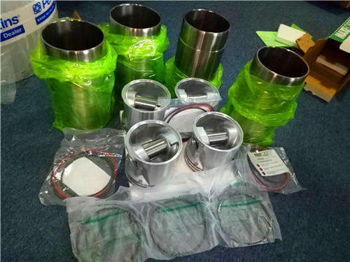
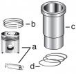
约翰迪尔 3029 2.9D 活塞(米) RE61467
美国强鹿JOHN DEERE柴油发电机配件及发动机配件:
CD3029DF128、CD4039DF008、CD4045TF258、PE4045、CD6068TF158、CD6068TF258、CD6068HF158、CD6068HF258、CD6081HF001A、4045TFM75、CD6081HF001B、CD6125HF070A、CD6125HF070B、RG6125、6135H458。4045DFM70, 4045TFM75, 6068TFM75, 6068TFM76、4039DFM RE522528、RE519774、RE532628、RE518176、RE507980、RE518503、RE522515、RE504836、RE509031/
强鹿JOHN DEERE柴油机配件、发动机配件、发电机组:
RE509032、RE59754、RE507284、RE59754、RE519626、RE508202、RE58935、T19044、RE62418、RE62419、RE521248、RE520842、C085004、RE509672、RE196945、RE191915、RE522688、RE522687、RE519774、RE532628、RE507980、RE531703、RE24619
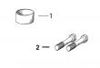
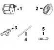
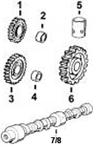
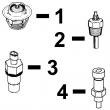
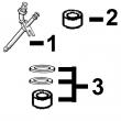
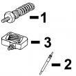
(cd3029df,cd4039df/tf,cd4045tf,cd6059tf,cd6068tf) pc2450 (20-jan-98) 23-21 pn=201 1i11 engine (cd6059tf/cd6068tf) oil filter/dipstick/guide, code 4010 filtre a huile/jauge/guide, code 4010 oelfilter/messstab/fuehrung, kode 4010 filtro olio/astina di livello/guida, codice 4010 filtro de aceite/aspilla/guia, codigo 4010 oljefilter/maesticka/styrning, koden 4010 cd35802 -un-01jan94 6 6 0 0 5 6 engine 9 8 key part no- part name qty serial no- t t remarks 1 t19044 oil filter 1 x x 2 at21535 dipstick 1 x x lgth 270mm (10-63") 3 r10093 o-ring 1 x x 4 r86819 threaded nipple 1 x x lgth 167mm (6-57") 5 14h826 nut 1 x x 1/2" 23-22 genset power units (cd3029df,cd4039df/tf,cd4045tf,cd6059tf,cd6068tf) pc2450 (20-jan-98) pn=202 1i12 engine (cd6059tf/cd6068tf) oil pump, code 5010 pompe a huile, code 5010 oelpumpe, kode 5010 pompa dell’olio, codice 5010 bomba de aceite, codigo 5010 oljepump, koden 5010 cd39105a -un-17aug95 6 0 5 engine 9 key part no- part name qty serial no- t remarks 1 14h826 nut 1 x 1/2"-13unc 2 t20298 gear 1 x z=33, helicoidal tooth,denture helicoidale, schraegverzahnung,dentutara elicoidale, dentura helicoidal,skruvhju***rev 3 - oil pump 1 x marked r54615, order re52020 4 r57059 cap screw 1 x lgth=70mm (2-75"), up 5 12h304 lock washer 2 x 3/8" 6 r59409 cap screw 2 x lgth 102mm (3-89"), low 7 re64211 oil pump intake 1 x a=114mm (4-56"), incl- instructions,anleitung,istruzioni, instrucciones,anvisningar 8 r61871 o-ring 1 x 9 r74354 o-ring 1 x 10 r115280 oil tube 1 x genset power units (cd3029df,cd4039df/tf,cd4045tf,cd6059tf,cd6068tf) pc2450 (20-jan-98) 23-23 pn=203 1i13 engine (cd6059tf/cd6068tf) oil pump kit pompe a huile oelpumpe, teilesatz pompa dell’olio, serie pezzi bomba de aceite, juego oljepump, sats cd39128 -un-01jan94 6 0 5 engine 9 key part no- part name qty serial no- t remarks 1 re52020 kit ar x 2 14h826 nut 1 x 1/2"-13unc 3 - oil pump 1 x marked r54615, ord re52020 4 r61871 o-ring 1 x 5 r74354 o-ring 1 x 6 r113752 oil tube na x w/ color mark, marquage couleur, farbige markierung, marcatura colore, marca de color, faergidentifikation, appl 7 r115280 oil tube 1 x 8 r97185 o-ring 1 x 9 r75892 o-ring ar x 23-24 genset power units (cd3029df,cd4039df/tf,cd4045tf,cd6059tf,cd6068tf) pc2450 (20-jan-98) pn=204 1i14 engine (cd6059tf/cd6068tf) oil pump/heavy-duty, code 5003 pompe a huile/debit augmente, code 5003 oelpumpe/verstaerkte ausfuehrung, kode 5003 pompa dell’olio/versione rinforzata, codice 5003 bomba de aceite/tipo reforzado, codigo 5003 oljepump/forstarkt utforande, koden 5003 cd23309a -un-30aug95 6 0 6 engine 8 key part no- part name qty serial no- t remarks 1 re65580 kit 1 x (sub for ar63037, this application) 2 r59409 cap screw ar x lgth 102mm (3-89") r81072 cap screw ar x lgth 99mm (3-93") ord r59409, appl 3 r61871 o-ring 1 x 4 r27564 o-ring 1 x (sub for r77052) 5 t20298 gear 1 x z=33, helicoidal tooth, denture helicoidale, schraegverzahnung, dentura elicoidal, dentura helicoidal, skruvhju***rev, 6 14h826 nut 1 x 1/2"-13unc 7 r120394 oil tube 1 x 8 ar66402 oil pump intake 1 x genset power units (cd3029df,cd4039df/tf,cd4045tf,cd6059tf,cd6068tf) pc2450 (20-jan-98) 23-25 pn=205 1i15 engine (cd6059tf/cd6068tf) filler neck/cover, code 1299 goulotte de remplissage/couvercle, code 1299 einfuellstutzen/deckel, kode 1299 bocchettone di riempimento/coperchio, codice 1299 boca de llenado/tapadera, codigo 1299 paafyllningshals/skyddskaapa, koden 1299 cd23133 -un-01jan94 6 6 0 0 5 6 engine 9 8 key part no- part name qty serial no- t t remarks 1 r97352 gasket 1 x x 2 t23260 cover 1 x x 3 24m7106 washer 2 x x 0-394" x 0-709" x 0-098" 4 19h2284 cap screw 1 x x 3/8" x 7/8" 5 19h1726 cap screw 1 x x 3/8" x 2-1/4" 23-26 genset power units (cd3029df,cd4039df/tf,cd4045tf,cd6059tf,cd6068tf) pc2450 (20-jan-98) pn=206 1i16 engine (cd6059tf/cd6068tf) timing gear cover, code 4499 without tachometer drive&without magnetic pick-up couvercle de distribution, code 4499 sans entrainement de tachymetre et sans capteur magnetique steuergehaeuse, kode 4499 ohne drehzahlmesserantrieb und ohne magnetischer impu***eber coperchio distribuzione, codice 4499 senza comando tachimetro e senza sen***e magnetico contagiri tapa de la distribucion, codigo 4499 sin mando tacometro y sin captador magnetico tidhjulskapa, koden 4499 utan drivning varmaetre och utan magnetgivare cd37324 -un-17oct94 6 6 0 0 5 6 engine 9 8 key part no- part name qty serial no- t t remarks 1 19h3065 cap screw 5 x x 3/8" x 2" 2 24m7106 washer 13 x x 10 x 18 x 2-500 mm 3 19h1726 cap screw 1 x x 3/8" x 2-1/4" 4 19h2733 cap screw 4 x x 3/8" x 2-3/8" 5 19h3031 cap screw 2 x x 3/8" x 2-1/2" 6 19h2549 cap screw 1 x x 3/8" x 1-7/8" 7 - cover 1 x x aluminium,alluminio,aluminio,aluminium, marked r122417, ord re51527 8 r97454 gasket 1 x x 9 re52977 drain plug 1 x x m42 x 2 10 51m7049 o-ring 1 x x 38-600 x 2-900 mm 11 r91692 plug 1 x x 1"-16unc 12 a4827r washer 1 x x 13 24h1290 washer ar x x 21/64" x 3/4" x 0-035" 14 t27658 spring 1 x x 15 r83169 valve 1 x x genset power units (cd3029df,cd4039df/tf,cd4045tf,cd6059tf,cd6068tf) pc2450 (20-jan-98) 23-27 pn=207 1i17 engine (cd6059tf/cd6068tf) timing gear cover kit couvercle de distribution, jeu de pieces steuergehaeuse, teilesatz coperchio distribuzione, serie pezzi tapa de la distribucion, jeugo tidhjulskapa, sats cd37327a -un-20jul95 6 6 0 0 5 6 engine 9 8 key part no- part name qty serial no- t t remarks 1 re51527 kit ar x x 2 19h3065 cap screw 5 x x 3/8" x 2" 3 24m7106 washer 13 x x 10 x 18 x 2-500 mm 4 19h2733 cap screw 4 x x 3/8" x 2-3/8" 5 19h3031 cap screw 2 x x 3/8" x 2-1/2" 6 19h2549 cap screw 1 x x 3/8" x 1-7/8" 7 19h1726 cap screw 2 x x 3/8" x 2-1/4" 8 19h2284 cap screw 1 x x 3/8" x 7/8" 9 ar67942 seal 1 x x 10 re52977 drain plug 1 x x m42 x 2mm 11 51m7049 o-ring 1 x x 38-600 x 2-900 mm 12 t23260 cover 1 x x 13 r97352 gasket 1 x x 14 r91692 plug 1 x x 15 a4827r washer 1 x x 1" x 1-1/4" x 0-064" 16 - cover 1 x x aluminium,alluminio,aluminio,aluminium, marked r114217, order re51527 17 r97454 gasket 1 x x 18 51m7044 o-ring 1 x x 0-681" x 0-087" 19 re38028 sen*** 1 x x 20 r65607 terminal 1 x x 21 - ground cable 1 x x lgth 150mm (5-90") mf r77499 22 r77491 terminal 1 x x - r77499 wire ar x x lgth 30-5m (100 ft) 23-28 genset power units (cd3029df,cd4039df/tf,cd4045tf,cd6059tf,cd6068tf) pc2450 (20-jan-98) pn=208 1i18 engine (cd6059tf/cd6068tf) closing for tachometer drive, code 4499 obturation pour entrainement de tachymetre, code 4499 abdeckung fuer drehzahlmesserantrieb, kode 4499 coperchio per comando tachimetro, codice 4499 tapa para mando tacometro, codigo 4499 lock foer drivning varvmaetare, koden 4499 cd36525 -un-01jan94 6 6 0 0 5 6 engine 9 8 key part no- part name qty serial no- t t remarks 1 m1746t drain plug 1 x x 7/8"-14unf 2 h1058r washer 1 x x genset power units (cd3029df,cd4039df/tf,cd4045tf,cd6059tf,cd6068tf) pc2450 (20-jan-98) 23-29 pn=209 1i19 engine (cd6059tf/cd6068tf) idle gear, code 3601 pignon de distribution, code 3601 steuerrad, kode 3601 ingranaggio distribuzione, codice 3601 engranaje de distribucion, codigo 3601 tidhjul, koden 3601 cd39157 -un-01jan94 6 6 0 0 5 6 engine 9 8 key part no- part name qty serial no- t t remarks 1 t26327 screw 1 x x 2 r101227 thrust washer 1 x x 14-7mm x 58mm (0-578" x 2-28") front 3 ar91660 gear 1 x x (marked r70182) z = 55, helicoidal tooth, denture helicoidale, schraegverzahnung, dentatura elicoidale, dentura helicoidal, skruvhju***rev, up 4 t20034 bushing 1 x x 5 r109863 pin 1 x x o-d- 44-5mm (1-75") 6 r101225 thrust washer 1 x x 22mm x 60mm (0-866" x 2-36") rear 23-30 genset power units (cd3029df,cd4039df/tf,cd4045tf,cd6059tf,cd6068tf) pc2450 (20-jan-98) pn=210 1i20 engine (cd6059tf/cd6068tf) idle gear, code 3601 pignon de distribution, code 3601 steuerrad, kode 3601 ingranaggio distribuzione, codice 3601 engranaje de distribucion, codigo 3601 tidhjul, koden 3601 cd39158 -un-01jan94 6 6 0 0 5 6 engine 9 8 key part no- part name qty serial no- t t remarks 1 14h865 nut 1 x x 1/2"-20unf 2 r101227 thrust washer 1 x x 14-7mm x 58mm (0-578" x 2-28") front 3 at24252 gear 1 x x (marked t26322) z = 45, helicoidal tooth, denture helicoidale, schraegverzahnung, dentatura elicoidale, dentura helicoidal, skruvhju***rev, low 4 t26321 bushing 1 x x 5 r109863 pin 1 x x o-d- 44-5mm (1-75") 6 r101225 thrust washer 1 x x 22mm x 60mm (0-866" x 2-36") rear 7 r100105 washer 1 x x 13-5mm x 30mm (0-531" x 1-18") rear 8 19h3011 cap screw 1 x x 1/2" x 2-1/8" genset power units香港岛约翰迪尔装载机发动机主线束代理,自贡约翰迪尔6068柴油机张紧轮代理,沈阳约翰.迪尔滤清器RE59754批发,昆明强鹿左平衡轴TRE500449厂家价格,淮南强鹿气门弹簧R518872供货商,张家界约翰迪尔3029DF128机体厂家供货,遂宁约翰迪尔强鹿活塞环信息,赤峰johndeere约翰迪尔强鹿柴油发动机起动机RE70960供货商,黄石约翰迪尔曲轴RE534314代理商,海北JohnDeere排气门异管RE518083供应商,阜阳强鹿柴油机预热塞TRE504580信息,黄山强鹿柴油机增压器RE509435价格行情,重庆约翰迪尔RE30250批发,常德强鹿柴滤RE529644的价格,鄂州约翰迪尔强鹿凸轮轴R522884诚信推荐,恩施强鹿6090柴油机止推轴承瓦批发,阿里强鹿滤芯滤清器RE21748一级代理,合肥约翰迪尔加大主轴瓦RE65911批发,铜川强鹿柴油机柴油过滤器总成RE504819哪家好,淮南johndeere约翰迪尔强鹿柴油机油泵找哪家,防城港强鹿缸套阳水圈AR65507诚信推荐,厦门强鹿排气门RE518081多少钱,拉萨强鹿柴油机AT21132止推轴承公司,长沙约翰迪尔机油底壳垫片R521498批发,平顶山johndeere约翰迪尔强鹿柴油机气门室盖垫哪家好,海西约翰迪尔柴油机排气门导管R119132找哪家,安阳强鹿6068柴油机气门锁夹哪里买,泉州约翰迪尔强鹿修理包厂家供货,嘉峪关约翰迪尔燃油输油泵TRE68345诚信推荐,延安johndeere约翰迪尔强鹿6090发动机配件哪里买,南阳强鹿6081发动机活塞公司,黄冈美国约翰迪尔输油泵哪家买,茂名约翰迪尔修理包RE527833厂家价格,郑州johndeere约翰迪尔强鹿柴油机热交换器多少钱,辽源约翰迪尔拖拉机发动机活塞价格行情,淮南强鹿6090柴油机小修包多少钱,株洲美国JohnDeere水泵总成RE505980/RE505981一级代理,贵港约翰迪尔联合收割机发动机缸盖信息,郑州约翰迪尔C240联合收割机发动机配件找哪家,厦门强鹿连杆瓦RE529318公司,崇左约翰迪尔联合收割机发动机活塞环供应商,香港岛强鹿6090柴油发动机曲轴齿环信息,海口约翰迪尔PE6068发电机缸套组件哪家买,黔南约翰迪尔柴油发电机组缸盖供货商,吐鲁番美国原装6068约翰迪尔柴油发动机机油滤清器RE504836哪家好,宝鸡强鹿JOHNDEERE柴油发动机原厂活塞环厂家批发,庆阳约翰迪尔3029柴油机连杆瓦诚信推荐,辽源强鹿柴油机马达哪家好,淮北约翰迪尔4045气门室盖垫片哪里买,唐山美国JohnDeere缸垫RE522278诚信推荐,新竹强鹿前油封RE543639厂家价格,昌吉约翰迪尔曲轴RE535300批发,巴音郭楞约翰迪尔加大止推轴承瓦RE504199找哪家,南通约翰迪尔E240/E240LC挖掘机发动机配件的价格, (cd3029df,cd4039df/tf,cd4045tf,cd6059tf,cd6068tf) pc2450 (20-jan-98) 23-31 pn=211 1i21 engine (cd6059tf/cd6068tf) universal front plate, code 3601 plaque avant universelle, code 3601 universelle front plate, kode 3601 piastra anteriore universale, codice 3601 placa delantero universal, codigo 3601 universalfrontplata, koden 3601 cd35803a -un-01jan94 6 6 0 0 5 6 engine 9 8 key part no- part name qty serial no- t t remarks 1 r131794 engine cylinder head gasket 1 x x (sub for r90648) 2 12h324 washer 5 x x 3/8" 3 t20166 screw 5 x x 4 r79863 plate 1 x x (also order (8) at21191&(2) at22919) 5 r79854 washer ar x x o-d- x i-d- 50mm x 46mm (1-96" x 1-81") 6 at21191 set screw 8 x x 5/16" x 0-380" 7 at22919 set screw 2 x x 3/8" x 0-380" 8 t23442 stud 3 x x lgth 36-6mm (1-44") x 5/16"-24ns x 5/16"-18unc 9 a22698 nut 3 x x 5/16"-18unc 23-32 genset power units (cd3029df,cd4039df/tf,cd4045tf,cd6059tf,cd6068tf) pc2450 (20-jan-98) pn=212 engine (cd6059tf/cd6068tf) memoranda genset power units (cd3029df,cd4039df/tf,cd4045tf,cd6059tf,cd6068tf) pc2450 (20-jan-98) 23-33 pn=213 1i22 engine (cd6059tf/cd6068tf) water pump, 404mm (15-9") code 2005 pompe a eau, 404mm (15-9") code 2005 wasserpumpe, 404mm (15-9") kode 2005 pompa dell’acqua, 404mm (15-9") codice 2005 bomba de agua, 404mm (15-9") codigo 2005 vattenpump, 404mm (15-9") koden 2005 cd35642b -un-07aug96 6 6 0 0 5 6 engine 9 8 key part no- part name qty serial no- t t remarks 1 re61065 water pump 1 x x (marked r90783) 2 r124585 pulley 1 x x 3 15h584 pipe plug 1 x x 1/2" 4 r48993 tube 2 x x id 16mm 5 r56809 gasket 1 x x 6 r56811 cover 1 x x tk 7mm 7 19h2633 cap screw 4 x x 3/8" x 1-1/2" 8 19h3031 cap screw 2 x x 3/8" x 2-1/2" 9 19h1765 cap screw 2 x x 3/8" x 1-3/4" 10 19h1726 cap screw 1 x x 3/8" x 2-1/4" 11 14h1076 nut 1 x x 3/8" 12 19h2458 cap screw 1 x x 3/8" x 3" 13 t20243 gasket 1 x x 23-34 genset power units (cd3029df,cd4039df/tf,cd4045tf,cd6059tf,cd6068tf) pc2450 (20-jan-98) pn=214 1i23 engine (cd6059tf/cd6068tf) water pump kit pompe a eau, jeu de reparation wasserpumpe, teilesatz pompa dell’acqua, serie pezzi bomba de agua, juego vattenpump, sats cd40039 -un-07aug96 6 6 0 0 5 6 engine 9 8 key part no- part name qty serial no- t t remarks 1 re70143 kit ar x x with cast iron impeller, (sub for re62660) 2 r56461 o-ring 2 x x 3 r54641 gasket 1 x x 4 r56809 gasket 1 x x 5 t20243 gasket 1 x x genset power units (cd3029df,cd4039df/tf,cd4045tf,cd6059tf,cd6068tf) pc2450 (20-jan-98) 23-35 pn=215 1i24 engine (cd6059tf/cd6068tf) oil cooler, code 5907 refroidisseur d’huile, code 5907 oelkuehler, kode 5907 radiatore dell’olio, codici 5907 refrigerador de aceite, codigo 5907 oljekylare, koden 5907 cd37217 -un-01jan94 this parts listing is continued 23-36 genset power units (cd3029df,cd4039df/tf,cd4045tf,cd6059tf,cd6068tf) pc2450 (20-jan-98) pn=216 1i25 engine (cd6059tf/cd6068tf) 6 0 5 engine 9 key part no- part name qty serial no- t remarks 1 ar21837 clamp 8 x 2 r70438 hose 1 x 3 - hose 1 x lgth 60mm (2-36") mf r83063 4 r99255 line 1 x id 16mm (0-62") 5 r99256 line 1 x id 16mm (0-62") 6 r99254 hose 2 x 7 t31306 threaded nipple 1 -185747 x 13/16"-16un x lgth 71mm (2-79") r99252 threaded nipple 1 185748- x 13/16"-16un xlgth 62mm (2-44") 8 re38078 oil cooler 1 -185747 x (order re61769&r122389) behr, 8 plates,plaques,platten, piastra,placa,hyvel, re61769 oil cooler 1 185748- x behr, 8 plates,plaques,platten piastra,placa,hyvel 9 r70956 washer 1 -185747 x r125508 packing 1 x incl-w/ re61769 10 19h1726 cap screw 1 x 3/8" x 2-1/4" 11 24m7106 washer 1 x 10 x 18 x 2-500 mm 12 r53524 clamp 1 x 13 r99257 washer 1 x tk 5mm (0-196") - r83063 hose 1 x id x lgth 16mm x 2370mm (0-62"x 93-30") genset power units (cd3029df,cd4039df/tf,cd4045tf,cd6059tf,cd6068tf) pc2450 (20-jan-98) 23-37 pn=217 1j1 engine (cd6059tf/cd6068tf) adapter (oil cooler,filter) code 5904 adaptateur(refroidisseur d’huile,filtre) code 5904 adapter (oelkuehler,filter) kode 5904 adattatore (radiatore dell’olio,filtro) codice 5904 adaptador (refrigerador de aceite,filtro) codigo 5904 kopplingsanordning (oljekylare,filter) koden 5904 cd39118a -un-22aug95 this parts listing is continued 23-38 genset power units (cd3029df,cd4039df/tf,cd4045tf,cd6059tf,cd6068tf) pc2450 (20-jan-98) pn=218 1j2 engine (cd6059tf/cd6068tf) 6 0 6 engine 8 key part no- part name qty serial no- t remarks 1 t19044 oil filter 1 x 2 r54823 adapter 1 x 7/8"-14unf x 13/16"-16un 3 15h695 pipe plug 1 x 3/8"-18npt 4 19h1944 cap screw 1 x 3/8" x 2-3/4" 5 19h2633 cap screw 2 x 3/8" x 1-1/2" 6 r113701 adapter 1 x 7 r120146 gasket 1 x 8 r114097 gasket 1 x 9 r114096 housing 1 x 10 19h2552 cap screw 2 x 3/8" x 1-1/8" 11 u12198 o-ring 1 x 12 r109886 cover 1 x 13 r56462 o-ring 1 x 14 r109882 adapter 1 x lgth 90mm (3-54") 15 19h2733 cap screw 1 x 3/8" x 2-3/8" 16 - pipe plug na x this parts listing is continued genset power units (cd3029df,cd4039df/tf,cd4045tf,cd6059tf,cd6068tf) pc2450 (20-jan-98) 23-39 pn=219 1j3 engine (cd6059tf/cd6068tf) oil cooler (10 plates) with r114096 adapter, code 5904 refroidisseur d’huile (10 plaques) avec adaptateur r114096, code 5904 oelkuehler (10 platten) mit r114096 adapter, kode 5904 radiatore dell’olio (10 piastra) con r114096 adattatore, codice 5904 refrigeardor de aceite (10 placa) con r114096 adaptator, codigo 5904 oljekylare (10 hyvel) med r114096 kopplingsanordning, koden 5904 cd40034 -un-07nov95 this parts listing is continued 23-40 genset power units (cd3029df,cd4039df/tf,cd4045tf,cd6059tf,cd6068tf) pc2450 (20-jan-98) pn=220 1j4 engine (cd6059tf/cd6068tf) 6 0 6 engine 8 key part no- part name qty serial no- t remarks 1 ar21837 clamp 6 x 2 - hose 2 x lgth 80mm (3-14") mf r83063 3 r122286 line 1 x od 16mm (0-62") 4 r122288 hose 1 x id 16mm/19mm (0-62"/0-75") 5 at18904 clamp 2 x 6 r122287 line 1 x od 16mm (0-62") 7 re50122 oil cooler 1 x modine, 10 plates,plaques,platten, piastra,placa,hyvel 8 r70956 washer 1 x 9 19h1726 cap screw 1 x 3/8" x 2-1/4" 10 24m7106 washer 1 x 10 x 18 x 2-500 mm 11 r53524 clamp 1 x 12 r99257 washer 1 x tk 5mm (0-196") 13 r56947 drain plug 1 x - r83063 hose 1 x id x lgth 16mm x 2370mm (0-62" x 93-30") genset power units (cd3029df,cd4039df/tf,cd4045tf,cd6059tf,cd6068tf) pc2450 (20-jan-98) 23-41 pn=221 1j5 engine (cd6059tf/cd6068tf) thermostat cover, code 2102 couvercle de thermostat, code 2102 thermostatdeckel, kode 2102 coperchio termostato, codice 2102 tapadera termostato, codigo 2102 skyddskaapa termostat, koden 2102 cd37271 -un-17feb95 6 6 0 0 5 6 engine 9 8 key part no- part name qty serial no- t t remarks 1 19h1732 cap screw 1 x x 3/8" x 1-1/4" 2 r54639 cover 1 x x 3 19h3065 cap screw 2 x x 3/8" x 2" 4 r54638 gasket 1 x x 23-42 genset power units (cd3029df,cd4039df/tf,cd4045tf,cd6059tf,cd6068tf) pc2450 (20-jan-98) pn=222 1j6 engine (cd6059tf/cd6068tf) thermostat, code 2204 thermostat, code 2204 thermostat, kode 2204 termostato, codice 2204 termostato, codigo 2204 termostat, koden 2204 cd40509 -un-17feb95 6 6 0 0 5 6 engine 9 8 key part no- part name qty serial no- t t remarks 1 re48583 thermostat 2 x x 82°c (181°f) genset power units (cd3029df,cd4039df/tf,cd4045tf,cd6059tf,cd6068tf) pc2450 (20-jan-98) 23-43 pn=223 1j7 engine (cd6059tf/cd6068tf) thermostat housing, code 3901,3905 boitier de thermostat, code 3901,3905 thermostatgehaeuse, kode 3901,3905 sede termostato, codice 3901,3905 caja del termostato, codigo 3901,3905 termostathus, koden 3901,3905 cd37277 -un-17feb95 6 6 0 0 5 6 engine 9 8 key part no- part name qty serial no- t t remarks 1 19h2023 cap screw 2 x x 3/8" x 3-1/4" 2 r64268 housing 1 x (3901) r54637 housing 1 x (3905) 3 r54641 gasket 1 x x 4 15h584 pipe plug 1 x x 1/2"-14npt 5 r56461 o-ring 2 x x 6 r55967 tube 1 x x 23-44 genset power units (cd3029df,cd4039df/tf,cd4045tf,cd6059tf,cd6068tf) pc2450 (20-jan-98) pn=224 1j8 engine (cd6059tf/cd6068tf) pulley with dampener, code 1308 poulie a amortisseur, code 1308 riemenscheibe with daempfer, kode 1308 puleggia con parastrappi, codice 1308 polea con amortiguador, codigo 1308 daemparskiva, koden 1308 cd37502 -un-01jan94 6 6 0 0 5 6 engine 9 8 key part no- part name qty serial no- t t remarks 1 19h2473 cap screw 1 x x 1/2" x 1-3/4" 2 r109086 spacer 1 x x tk x od = 10mm x 44mm (0-393" x 1-732") 3 re12820 pulley, with dampener 1 x x 4 r81989 sleeve 1 x x 5 h35244 ring 1 x x 6 26h27 shaft key 1 x x 5/16" x 1-1/8" genset power units (cd3029df,cd4039df/tf,cd4045tf,cd6059tf,cd6068tf) pc2450 (20-jan-98) 23-45 pn=225 1j9 engine (cd6059tf/cd6068tf) flywheel, code 1505 volant, code 1505 schwungrad, kode 1505 volano, codice 1505 volante, codigo 1505 svaenghjul, koden 1505 cd36402 -un-01jan94 6 6 0 0 5 6 engine 9 8 key part no- part name qty serial no- t t remarks 1 19h2993 cap screw 4 x x hs, sae 8, 1/2" x 1-1/2" 2 re58568 flywheel 1 x x (marked r122403) (sub for re56417) 3 r28811 ring gear 1 x x z=129, m 8/10, id 385mm (15-15") 23-46 genset power units (cd3029df,cd4039df/tf,cd4045tf,cd6059tf,cd6068tf) pc2450 (20-jan-98) pn=226 1j10 engine (cd6059tf/cd6068tf) flywheel housing, sae 3, 3 holes mouting flange, r-h- code 1421 carter de volant, sae 3, bride de fixation a 3 trous a droite, code 1421 schwungradgehaeuse, sae 3, befestigungsflansch mit 3 bohrungen, rechts, kode 1421 carcassavolano, sae 3, flangia di montaggio a 3 fori, a destra, codice 1421 carcasavolante, sae 3, brida de sujecion a 3 agjeros, a la derecha, codigo 1421 hus svaeghjul, sae 3, koden 1421 cd35628a -un-22aug95 6 6 0 0 5 6 engine 9 8 key part no- part name qty serial no- t t remarks 1 r120586 housing 1 x x 2 r104592 pipe plug 1 x x 1/8"-27npt, (sub for r21630) (7699) 3 15h584 pipe plug 1 x x 1/2"-14npt 4 19h3219 cap screw 8 x x 3/8" x 1-3/8" 5 19h1847 cap screw 2 x x 5/8" x 2-1/2" 6 r131768 plug 1 x x (sub for r83556) 7 r97351 gasket 1 x x 8 t22867 drain plug na x x 3/4"-16unf genset power units (cd3029df,cd4039df/tf,cd4045tf,cd6059tf,cd6068tf) pc2450 (20-jan-98) 23-47 pn=227 1j11 engine (cd6059tf/cd6068tf) flywheel housing, sae 2, 3 holes mounting flange, l-h-, code 1405 carter de volant, sae 2, bride de fixation 3 trous a gauche, code 1405 schwungradgehaeuse, sae 2, befestigungsflansch mit 3 bohrungen, links, kode 1405 carcassavolano, sae 2, flangia di montaggio a 3 fori, a sinistra, codice 1405 carcasavolante, sae 2, brida de sujecion 3 agujeros a la izquierda, codigo 1405 hus svaeghjul, sae 2, koden 1405 cd35625a -un-31aug95 6 0 6 engine 8 key part no- part name qty serial no- t remarks 1 ar70575 housing 1 x (marked r58967) 2 r104592 pipe plug ar x 1/8"-27npt, (7699) 3 19h1387 cap screw 4 x 5/8" x 2-1/4" 4 19h3219 cap screw 8 x 3/8" x 1-3/8" 5 r97351 gasket 1 x 6 r131769 plug 1 x (sub for r83556) 23-48 genset power units (cd3029df,cd4039df/tf,cd4045tf,cd6059tf,cd6068tf) pc2450 (20-jan-98) pn=228 engine (cd6059tf/cd6068tf) memoranda genset power units (cd3029df,cd4039df/tf,cd4045tf,cd6059tf,cd6068tf) pc2450 (20-jan-98) 23-49 pn=229 1j13 intake/exhaust air intake, code 1707,1710 pipe d’admission, code 1707,1710 einlasskruemmer, kode 1707,1710 collettore d’aspirazione, codice 1707,1710 colector de admicion de aire, codigo 1707,1710 avgasgrenroer, koden 1707,1710 cdb30051 -un-17aug95 3 4 0 0 2 3 engine 9 9 key part no- part name qty serial no- d d remarks 1 19h3065 cap screw 2 x x 3/8" x 2" 2 24m7096 washer 2 x x 10-500 x 18 x 1-600 mm 3 - air intake 1 -263023 x marked r128355, ord r84992,t58477 and ty9371, this application (1707) - air intake 1 263024- x marked r128355, ord r84992,t58477 and ty9371, this application (1710) - air intake 1 x marked r128355, ord r84992,t58477 and ty9371, this application (1707) r84992 air intake ar x x 4 r81275 gasket 1 x x 5 t58477 fitting ar x x 7/8"-14unf, (use with r84992) 6 ty9371 adhesive 1 x x loctite 271, 6ml (0-2 oz) t43513 adhesive ar x x loctite 271, 50ml (1-7 oz) 7 - cap screw ar x x 3/8"-16unc 25-2 genset power units (cd3029df,cd4039df/tf,cd4045tf,cd6059tf,cd6068tf) pc2450 (20-jan-98) pn=230 1j14 intake/exhaust intake manifold, code 1714 pipe d’admission, code 1714 einlasskruemmer, kode 1714 collettore d’aspirazione, codice 1714 colector de adm- de aire, codigo 1714 avgasgrenroer, koden 1714 cd37329 -un-31aug95 4 4 0 0 3 4 engine 9 5 key part no- part name qty serial no- t t remarks 1 19h3065 cap screw 2 x x 3/8" x 2" 2 12h304 lock washer 2 x x 3/8" 3 re46784 air duct 1 x x 4 r81275 gasket 1 x x 5 ar65294 clamp 2 x x 6 r121568 hose 1 x x 7 - pipe plug 1 x x 7/8"-14unf genset power units (cd3029df,cd4039df/tf,cd4045tf,cd6059tf,cd6068tf) pc2450 (20-jan-98) 25-3 pn=231 1j15 intake/exhaust intake manifold, code 1707 pipe d’admission, code 1707 einlasskruemmer, kode 1707 collettore d’aspirazione, codice 1707 colector de adm- de aire, codigo 1707 avgasgrenroer, koden 1707 cda38112 -un-17feb95 6 6 0 0 5 6 engine 9 8 key part no- part name qty serial no- t t remarks 1 19h3065 cap screw 2 x x 3/8" x 2" 2 12h304 lock washer 2 x x 3/8" 3 re26433 intake manifold 1 x x 4 r81275 gasket 2 x x 5 - plug 1 x x 7/8"-14unf, 6 ar65294 clamp 1 x x 7 r121568 hose 1 x x 25-4 genset power units 海西天峻县CAT喷油器249-0713商家,菏泽定陶县卡特cat电控单元一件代发,张掖临泽县Perkins柴油柴油机配件厂家销售中心,内蒙古自治通辽科尔沁CAT液压泵配件泵胆供应信息?,克孜勒苏阿图什卡特CATC13柴油发动机凸轮轴什么地方有?,咸阳泾阳县劳斯莱斯发电机P850零配件的地方在那?,河北保定定兴县威尔信逊P1000E-P2200E发电机维修保养正品配件,广元苍溪县帕金斯1104C发动机配件谁知道多少钱,成都双流县珀金斯发动机配件机油散热器管认准指定代理商,武汉东西湖沃尔沃充电发电机21935701送货到家更快,汕头濠江珀金斯发动机喷油嘴欢迎咨询?,泸州纳溪FGWilson发电机中冷器的价格多少?,朝阳双塔沃尔沃发电机大修包专业销售服务中心,harness/mounted in the vehicle. if the tvp module is mounted in the vehicle, it should be mounted vertically with the pigtail wires exit- ing form the bottom of the module. the mounting location should be away from battery fumes, engine heat&vibration, such as in a con- trol cabinet, vehicle chassis,/cab. mounting ears of the tvp mod- ule may not withstand overtightening of mounting bolts. the tvp module does not protect against sustained over-voltage to the ecu. the tvp module mates with the tvp connector in the engine wiring harness. the tvp module is not always required. some alternators have internal tvp protection. a tvp module will be provided if needed, depending on the alternator option specified. if you provide your own alternator, a tvp module must be used. reverse current protection the ecu has limited internal reverse current protection if the ecu power supply is connected in reverse. the ecu will not be damaged with reverse voltage up to 26.5 volts on a 12-volt system&36.0 volts on a 24-volt system. reverse current at higher voltages will damage the ecu. starter relay the standard engine wiring harness is designed for use with a starter relay located within 2 feet (600 mm) of the starter. under no circum- stances should the starter solenoid be operated directly from the key switch without a relay. engine application guidelines ag-15 - 15 july 2001 electronic engine controls jdec (12.5 l) the 21-pin deutsch connector on the engine wiring harness plugs directly into the bottom of the re162429 instrument panel. to oper- ate an engine with the re162429 instrument panel, you need only install the engine wiring harness, connect the power&ground to the battery, plug the 21-pin deutsch connector into the re162429 instrument panel,&turn the key. the re162429 panel operates on 12/24 volts. the following features are standard on the re162429 instrument panel: standard instrument panel features ? ignition switch ? panel mounted fuse ? adjustable 2-state throttle switches ? shutdown override button ? re68155 diagnostic gauge ? tachometer ? oil pressure analog gauge ? coolant temperature analog gauge. the following optional features are available. to use the optional fea- tures, just order the parts&plug in. connectors&panel cutouts are provided in the standard panel: optional instrument panel features ? re69667 analog throttle potentiometer ? re163436 percent load gauge ? re162422 12-volt voltage gauge ? re163277 24-volt voltage gauge ? re162427 audible warning alarm ? re162449 backlight dimmer control ? re162448 converter for 24-volt backlighting ? re506969 12-foot extension harness using the re508625 instrumentation&wiring kit the second easiest way to provide all the control system parts that do not come on the engine is to use the john deere re508625 instrumentation and wiring kit. figure ag-15 - 08, instrumentation&wiring kit, re508625 the re508625 instrumentation&wiring kit includes all the parts that are included in the re162429 instrument panel except for the adjustable 2-state throttle switches, which can be added by purchasing a separate re508626 switch kit. the re508625 kit includes ignition switch, shutdown override switch, all needed wiring connectors,&the re162450 databus module which can be used to add up to three additional auxiliary gauge displays (in addition to the included tach, coolant temp,&oil pressure gauges). all you need to add is the actual wires&a throttle control. all optional features of the re162429 panel also apply to the re508625 instrumentation kit. engine application guidelines ag-15 - 16 july 2001 electronic engine controls jdec (12.5 l) making your own instrumentation&controls if you choose not to use the re162429 instrument panel/the re508625 instrumentation kit, you will have to provide your own ignition switch, fuse holder, throttle device, wiring harness, diagnostics,&any other instrumentation&controls you need. all required electrical connections to the engine, including throttle, instrumentation, key switch, starter,&alternator connections, are made through a single 21-pin deutsch connector provided on the engine wiring harness. several special connectors are provided for optional features. figure ag-15 - 09, instrumentation connections 21-pin connector special connectors required ignition switch primary analog throttle potentiometer high / low throttle switch diagnostic gauge optional shutdown override adjustable 2-state throttle "bump" switches auxiliary gauges cruise control air cleaner restriction switch low coolant level switch external derate input external stop-engine input auxiliary warning lamp auxiliary stop-engine lamp secondary analog throttle potentiometer engine application guidelines ag-15 - 17 september 2001 electronic engine controls jdec (12.5 l) figure ag-15 - 10, minimum required wiring 21-pin connector key switch 5 amp diagnostic gauge high / low switch* analog throttle/emulator * * throttle&switch connections not required for gen-sets that start&operate at rated speed only minimum required wiring all required wiring attachments can be made through the 21-pin instru- mentation&controls connector. some kind of ignition switch is always required. diagnostics are also required. for 8.1l&12.5l engines, you must install the re68155 diagnostic gauge/equivalent can-based instrumentation. the re68155 diagnostic gauge is not strictly required on 4.5l&6.8l engines because they are also equipped with blink-code diagnostics. however, it is still highly recommended because it is the easiest way to meet all diagnostic&wiring requirements. if you do not use the re68155 diagnostic gauge on 4.5l&6.8l engines, you must provide a warning lamp, stop-engine lamp, hourmeter,&other desired instrumentation such as tachometer, oil pressure gauge,&coolant tem- perature gauge separately. for gen-set applications that start&operate at full rated speed only (1500/1800 rpm), it is not necessary to connect anything except the key switch&diagnostics. for industrial applications, the analog throttle circuit must also be com- pleted. if you choose to operate without an analog (potentiometer) throt- tle, you still must install a resister bridge to terminate the circuit. the high/ low speed select switch must also be connected on all industrial (non- gen-set) ecus. if you choose not to use the high/low select feature, this circuit can be easily terminated with a single resister. for details on wiring all required&optional circuits, refer to the follow- ing sections. engine application guidelines ag-15 - 18 july 2001 electronic engine controls jdec (12.5 l) basic instrumentation&controls harness for all required connections,&for the more common optional connections that are made through the 21-pin connector, refer to the following wiring diagram. this diagram provided a complete wiring harness to interface the 21-pin connector with your instrument panel. the connectors shown fit the recommended john deere gauges, switches, etc. listed. if you choose to use other components, different connectors may be required. figure ag-15 - 11, instrumentation&controls connections refer to the following sections for details on each connector. potentiometer analog engine application guidelines ag-15 - 19 july 2001 electronic engine controls jdec (12.5 l) 21-pin deutsch instrument panel connector the 21-pin deutsch connector makes the main connection between the engine&your instrumentation&controls. the re508625 instrumenta- tion&wiring kit includes this connector. if you provide your own harness, you will have to provide this connector with pin assignments per the fol- lowing chart. use (1) 57m7748 connector (deutsch hdp24-24-21pe), (5) r78068 12-ga to 14-ga pins (deutsch 0460-204-12141), (16) r78066 16-ga to 18-ga pins (deutsch 0460-202-16141),&(3) r78069 plugs (deutsch 114017). instrument panel connector pin assignments pin wire description used on a na na this pin is not currently used. b 022c battery power to "b" terminal of your ignition switch c 914b sen*** return to the primary analog throttle potentiometer/emulator d 422 starter relay to "start" terminal on your ignition switch e 050d ground grounded on engine side to the battery&ecu. use for any non-sen*** ground (lights, gauge power, etc) f 020f can shield to any can connectors including the diagnostic gauge g 012b battery power to ecu (switched) must be wired to the "ignition" terminal of key switch h n/a n/a this pin is not currently used j 412 alternator ignition must be wired to the "acces***y" terminal of a two-pole ignition switch. k n/a n/a this pin is not currently used l 915 primary analog throttle input voltage to center (sensing) terminal of the primary analog throttle potentiometer (or throttle emulator) m 911b +5 volts (sen*** power) to the throttle potentiometer n 918 shutdown override return to shutdown override switch p 464b shutdown override to shutdown override switch r 947 high/low speed select to the high/low speed select switch s 414b high/low speed return to the high/low speed select switch t 936c resume / coast / bump speed down to the 2-state throttle speed select switch and/or the cruise control resume/coast switch u 905e can low to the 9-&3-pin can connectors, diagnostic gauge and/or instrument panel databus module v 904e can high to the 9-&3-pin can connectors, diagnostic gauge and/or instrument panel databus module w 955c set / accelerate / bump speed up to the 2-state throttle speed select switch and/or the cruise control set/accelerate switch x 923 bump enable&brake enable to the cruise brake enable switch and/or 2-state throttle bump enable switch engine application guidelines ag-15 - 20 september 2001 electronic engine controls jdec (12.5 l) analog throttle potentiometer you must complete this circuit for all industrial applications, even if you don’t use the analog throttle feature. if you don’t use an analog potentiometer, you must install a throttle emulator (resister bridge) that sets the throttle in the low idle range. if this circuit is not connected on industrial applications, a fault code will be generated. the warning lamp will light&the system will revert to the secondary analog throttle and/or adjustable 2-state throt- tle inputs. if no throttle input is present on industrial applications, the system will revert to low idle. no connection is required on gen-set applications that are intended to run at rated speed only with no adjustability. the connector shown below will fit the re69667 analog throttle/the re503681 throttle emulator. the harness connection is a packard weather pack 3-cavity, female connector, #12020829, with male ter- minals, #12124582,&cable seals installed. note that these are the opposite terminals usually used with this connector. figure ag-15 - 13, analog throttle potentiometer if you do not use an analog potentiometer, you must install a resister bridge that sets the throttle in the low idle range. you can either use the re503681 throttle emulator with the connector shown above, or you can wire your own equivalent resister bridge into the appropriate pins on the 21-pin connector as shown below. the exact size of the resisters is not important, as long as total resistance is 2,000-15,000 ohms,&the small resister is 6% to 20% of the large resister size. figure ag-15 - 14, re503681 throttle emulator (or equivalent) a b c c 911 brown 18 awg to pin m on 21-pin connector b 915 orange a 914 yellow 18 awg to pin c on 21-pin connector pin circuit color size destination 18 awg to pin l on 21-pin connector 21-pin connector c l m 4700 ohms 510 ohms ignition switch the ignition switch must be connected on all applications. all connections are made through the 21-pin connector. pin j on the 21- pin connector is the alternator ignition circuit. the alternator ignition must be isolated from switched power to the ecu (pin g) by using a 2-pole ignition switch/the engine may not shut down when the key is turned off. if necessary to support heavy acces***y loads through the key switch (flood lights, electric motors, etc.), battery power to the "bat" terminal of the key switch can be taken from a separate heavy-duty source instead of pin b in the 21-pin connector. pin b is provided for your convenience to simplify wiring on simple power unit installations. however, the fuse&wire gauges are sized for engine fuel system power requirements only. it should not be used if additional loads of more than a few amps will be carried through the key switch. the starter relay&alternator ignition connections can also be made through separate circuits instead of pins j&d. only switched power to the ecu must be connected through the 21-pin connector. figure ag-15 - 12, ignition switch connections key switch battery ignition start acc. to fuse&diagnostic gauge to the b+ terminal of the battery to the starter relay switched b+ power to the ecu (on/off) to alternator ignition b d g j 21-pin connector engine application guidelines ag-15 - 21 february 2002 electronic engine controls jdec (12.5 l) throttle potentiometer pre-adjustment procedure on industrial applications, if the voltage on 21-pin connector pin l goes above 4.75 volts/below 0.25 volts, the ecu will generate a fault code&return the engine to slow idle. it does this so that a break/short circuit in the wire does not cause the engine to go to fast idle unexpectedly. to prevent error codes&unexpected changes in speed, the fast and slow idle s*** on the throttle potentiometer must be adjusted so that the voltage on pin l cannot go below 0.25 volt/above 4.75 volts. industrial (non-gen-set) applications also have an auto-cal feature that automatically adjusts the analog throttle range to match your sen- ***. once the s*** are adjusted to limit low&fast idle voltage, the auto-cal feature of the ecu will check the exact range of your throttle potentiometer&adjust the ecu to that range. however, your initial installation must be within certain resistance limits for the auto-cal feature to work. before plugging it into the wiring harness, adjust the throttle potenti- ometer using the following procedure: 1. with the potentiometer against the slow idle stop, adjust the stop so that the resistance measured between the ground&wiper connections of the potentiometer (21-pin connector pins c&l) is between 6%&20% of overall potentiometer resistance. 2. with the potentiometer against the fast idle stop, adjust the stop so that the resistance measured between the power&wiper con- nections of the potentiometer (21-pin connector pins m&l) is also between 6%&20% of overall potentiometer resistance. this does not have to be a precise adjustment. the auto-cal feature will make a precise adjustment automatically. once it has been done a few times, you will probably find that adjusting each throttle stop screw a predetermined number of turns is accurate enough. the re69667 analog throttle is a multi-turn 5000-ohm potentiometer throttle designed for stationary applications. many other throttle styles, including various foot pedal throttles are available from morse, williams controls,&other suppliers. any potentiometer-style ana- log throttle will work, as long as total resistance is in the 2,000-15,000 ohm range. figure ag-15 - 15, re69667 analog throttle gen-set load sharing modules a commercial gen-set load sharing module that can provide a throttle input signal in the 1 to 4 volt range can be wired directly to the analog throttle input (pin l). if the load sharing module provides for a refer- ence voltage connection, a 5-volt reference voltage should be taken from pin m. sen*** ground (pin c) should not be used to ground the load sharing module. engine speed stability problems can result under some circumstances. the load sharing module should be grounded directly to the engine cylinder block,/to the negative ter- minal of the battery. engine application guidelines ag-15 - 22 september 2001 electronic engine controls jdec (12.5 l) high / low select (“idle”) switch the high/low select switch circuit must be connected on all industrial applications, even if you do not intend to use the fea- ture. the high/low select switch is part of the adjustable 2-state throttle. the high/low switch switches between preset high speed&low speed operating points (normally the factory high idle&low idle). the switch must be in the low-speed position for the analog (potenti- ometer) throttle to work. you must either provide a high/low switch or you must terminate the circuit through a resister. if this circuit is not connected on industrial applications, a fault code will be generated. the warning lamp will light&the system will revert to the analog throttle inputs. if no throttle signal is present on industrial applications, the system will revert to low idle. no connec- tion is required on gen-set applications that are intended to run at rated speed only with no adjustability. the john deere re162425 switch is a single-pole, double-throw switch, designed to be used for the high/low select switch. it can be purchased separately,/as part of the re508626 switch kit figure ag-15 - 17, re162425 high / low select switch 390 ohm (min. speed) 1300 ohm (max. speed) a b potentiometer without mechanical adjustment s*** if a potentiometer without fast&slow idle s*** is used, additional fixed resistors can be wired in series with 21-pin connector pins c and m as shown below to prevent the analog throttle voltage from going outside the upper&lower limits&generating a fault code. for the auto-cal system to work properly, each added resistor should be between 6%-20% of the nominal throttle potentiometer resistance. total resistance of the potentiometer&both resistors should be in the range of 2000 to 15,000 ohms. you do not have to connect this circuit for gen-set applications. gen- set ecus default to rated speed (1800/1500 rpm),&do not gen- erate a fault code if the throttle isn't connected. if the analog throttle is not connected, the engine will run at rated speed (1800/1500) only, with no adjustment. figure ag-15 - 16, potentiometer without mechanical adjustment s*** adjustable 2-state throttle the adjustable 2-state throttle wiring consists of three switches, the high/low select (“idle”) switch, the speed select (“bump”) switch, and the bump enable switch. only the high/low select switch must be con- nected. the bump feature is optional 5,000 ohms slow idle position fast idle position 21-pin connector, pin c 21-pin connector, pin m 21-pin connector, pin l added 500-ohm resistor added 500-ohm resistor engine application guidelines ag-15 - 23 july 2001 electronic engine controls jdec (12.5 l) this connector must not be left open on ecus equipped with the adjustable 2-state throttle. if the 2-state toggle-switch throttle is not used, one of the two following things must be done: 1. for continuous operation at the factory preset rated speed, with no ability to operate at low idle/any other reduced speed, a 1300-ohm resistor can be permanently wired between pins r and s. 2. for use with an analog throttle potentiometer without a 2-state toggle-switch throttle, a 390-ohm resistor should be permanently wired between pins r&s. speed select (“bump”) switch the speed select switch, also known as the “bump” switch, is used to increase&decrease the minimum&maximum operating speeds. it must be used with the bump enable switch (see below). the bump switch works like the "accel"&"coast" buttons on a cruise control. a momentary tap on the switch bumps the speed up or down about 10 rpm. if the switch is held down, speed will continue to ramp up/down continuously until the switch is released, then it will lock in at whatever rpm it has reached at that point. you are not required to connect this circuit unless you intend to use this feature. if you do use this feature, you can use the john deere re162423 bump switch shown below,/any single-pole, double-throw, momentary switch with a detented center off position. figure ag-15 - 20, re162423 speed select (bump) switch a b c bump down bump up the mating connector to this switch is a packard metri-pack 150 series two-cavity female connector, #12052641, with #12048074 sealed female terminals, cable seals&a #12052634 tpa/sec- ondary lock. figure ag-15 - 18, high / low select pin connectors the switch contains two resistors, 390-ohm&1.3k-ohm. when in the slow idle position, the 390-ohm resistor is placed in the circuit and when in the high-idle position, the 1.3k-ohm resistor is placed in the circuit. if you do not use the re162425 high/low selector switch, you must provide your own switch,/terminate the circuit with a resister as shown below. figure ag-15 - 19, high / low select connect without re162425 a 914 yellow 18 awg to pin "s" on 21-pin connector b 947 violet pin circuit color size destination 18 awg to pin "r" on 21-pin connector a b 390 ohm (min. speed) 1300 ohm (max. speed) r s for switched high / low operation (re162425 switch,/equivalent) r 1300 ohm (max. speed) s locked at rated speed 390 ohm (min. speed) r s 21-pin connector locked at low idle for analog throttle only 21-pin connector 21-pin connector engine application guidelines ag-15 - 24 july 2001 electronic engine controls jdec (12.5 l) bump enable switch the bump enable switch is used in conjunction with the speed select switch to adjust minimum&maximum operating speed. the bump enable switch enables the speed select switch to be read by the ecu. to adjust the minimum/maximum operating speed, the bump enable switch&speed select switch must be operated simulta- neously. this prevents unexpected operating speed changes in the event of a failure of the speed select circuit. figure ag-15 - 23, re162424 bump enable switch as a convenience for the operator, we offer the re162424 bump enable switch with two enabling positions, up/down, with the center “off.” that way, when placed next to the re162423 bump switch, both switches can be pressed simultaneously by laying your finger across them. the switch is a single-pole, double-throw, momentary with a detented center “off” position. both active positions are wired to con- nect the same two-wire circuit when pressed. figure ag-15 - 24, throttle switches unlock unlock a b c re162424 bump-enable switch re162423 speed select (bump) switch the mating connector for the re162423 switch is shown below. it is a packard metri-pack 150 series three-cavity male connector, #12129615, with #12045773 sealed male terminals, #12048086 cable seals,? tpa/secondary locks. figure ag-15 - 21, re162423 mating connector if you choose not to use the re162423 switch, you can use any sin- gle-pole, double-throw, momentary switch with a detented center “off” position, wired as shown below figure ag-15 - 22, re162423 wiring diagram to permanently set high&low speeds, press the bump enable but- ton (3) three times after adjustment. both preset speeds (high and low) will be remembered, even if the ignition is turned off/the bat- tery is disconnected. if the adjustable 2-state toggle-switch throttle is not used, nothing is required to be plugged in to this connector c 936 blue 18 awg to pin "t" on 21-pin connector b 012 red pin circuit color size destination 18 awg to ign circuit from key switch a b c a 955 green 18 awg to pin "w" on 21-pin connector bump down bump up pin t, 21-pin connector key switch ign. terminal pin w, 21-pin connector re162423 (or equivalent) 2-pole momentary switch engine application guidelines ag-15 - 25 july 2001 electronic engine controls jdec (12.5 l) re68155 diagnostic gauge we require the re68155/equivalent sae j1949 can based on-board diagnostic system for all 12.5l applications. the re68155 diagnostic gauge is a complete on-board engine diagnostic&display system. it includes built-in "warning"&"stop engine" lights to alert the operator of any problems,&it digitally displays diagnostic codes, rpm, hours, oil pressure, coolant temperature, voltage, engine load, fuel consumption, manifold temperature&other engine parameters. figure ag-15 - 27, re68155 diagnostic gauge there are three ways to connect the re68155 diagnostic gauge to your system: 1. wire the re68155 diagnostic gauge directly to the 21-pin instru- mentation&controls connector. 2. use the re507276 adapter harness to connect the diagnostic gauge to the 9-pin diagnostic connector. 3. use the re162450 databus module to connect the re68155 diagnostic gauge&up to six auxiliary gauges plus backlighting to the 21-pin instrumentation&controls connector. the mating connector on the re162424 bump enable switch is shown below. it is a packard metri-pack 150 series three-cavity female connector, #12110293, with #12048074 sealed female termi- nals, #12048086 cable seals,? tpa/secondary locks. the unused cavity has a #12059168 cavity plug installed. figure ag-15 - 25, re162424 mating connector if the re162424 switch is not used, any similar single-pole, double- throw, momentary switch with a detented center off position switch, or a simple single-pole momentary switch can be wired as shown below to provide the bump-enable function. figure ag-15 - 26, re162424 wiring diagram if the speed bump feature is not used, this circuit does not need to be connected. a 923 orange 18 awg to pin x on 21-pin connector b 012 red pin circuit color size destination 18 awg to ign circuit from key switch c cavity plug unused a b c unlock unlock double-throw momentary switch pin x, 21-pin connector key switch ign. terminal connector key switch ign. terminal momentary push engine application guidelines ag-15 - 26 july 2001 electronic engine controls jdec (12.5 l) wiring the diagnostic gauge directly to the 21-pin connector refer to the following illustration to connect the re68155 diagnostic gauge to the 21-pin instrumentation&control connector. figure ag-15 - 28, re68155 diagnostic gauge pin "e" is the battery connection,&has an allowable voltage range of 9 to 32 volts with respect to pin d,/ground, for proper operation. key switch battery ignition start acc. 21-pin connector backlight dimmer sae 1939/11 - - twisted & shielded cable 120-ohm resistor h g f e a b c d 5-amp fuse diagnostic gauge connector f u v e can shield can low can high ground backlight circuit optional engine application guidelines ag-15 - 27 july 2001 electronic engine controls jdec (12.5 l) the can h&can l wires must be connected through a 120-ohm resister on the end of your harness where they connect to the diag- nostic gauge. if you use more than one can-based device, only one 120-ohm resister should be connected. it must be connected at the end of the can buss, where the furthest device from 21-pin connec- tor is connected. if you want backlighting, just follow the schematic&find the corre- sponding pins you need in the 21-pin connector. if dimming is desired, normally a dimmer (re162449) is used. this reduces the voltage to the backlighting from full voltage (about 14 volts for a 12- volt system) for full brightness to about 2 volts for the lowest bright- ness. if a 24-volt system is used, the voltage regulator (re162448) should be used to provide 12 volts for the backlighting. the backlight system is an led. leds require about 2 volts to turn on. the voltage range for the backlighting is about 2 volts to 16 volts. a 5-amp fuse with the following characteristics (per sae j1284) must be used: rating blow time 110% 100 hours, minimum 135% 1500 seconds, maximum 200% 5 seconds, maximum 350% 0.08 seconds, minimum the mating connector for the diagnostic gauge is a packard metri- pack, 150 series, 8-way female connector. part part number female connector assembly 12047937 tpa 12066304 sealed terminals, 16-18 awg(1.0-.8 sq mm) 12048074 sealed terminals, 20-22 awg(.5-.35 sq mm) 12084200 cable seals, 2.85-2.03 mm dia 12048086 cable seals, 2.15-1.60 mm dia 12089678 cable seals, 1.70-1.29 mm dia 12048087 the terminal&cable seals should be selected for the size of wire used. all of the terminal positions on the diagnostic gauge connector are used. if the mating connector does not use a position for a partic- ular application, it should be filled with a cavity plug, part number 12059168, to ensure sealing of the entire connector assembly. all the connecting wires you need are in the 21-pin instrument panel connector. if you aren’t going to use backlighting/auxiliary gauges, you only have to hook up can h, can l, can shield, power, and ground to the gauge. power must come from the ignition terminal of the key switch through a 5-amp fuse. sae 1939/11-type shielded cable should be used to connect the can h, can l&can shield wires from the 21-pin connector to the gauge. sae 1939/11-type shielded cable is available from many com- mercial sources including champlain cable. to make your own cable, the can h&can l wires need to be twisted together along their entire length,&shielded with a metal cover. the can shield wire should be a bare copper wire running inside (and contacting) the metal shield alongside the twisted can h&can l wires. it is a good idea to switch to an insulated wire where the wire exits the shield so it does not ground out against anything. engine application guidelines ag-15 - 28 july 2001 electronic engine controls jdec (12.5 l) using the re507276 diagnostic gauge adapter harness an easier way to connect the re68155 diagnostic gauge is to use the re507276 adapter harness, available through service parts. the re507276 adapter harness connects with the 9-pin deutsch diagnostic connector, which is present on every engine wiring harness. it includes connectors for the re162449 backlight dimmer&the re162448 24-volt-to-12-volt converter, which is required to operate the 12-volt backlight system with a 24- volt engine electric system. it can also be used with the available re508492&re508493 jumper wires for fixed (constant&non-dimmable) backlighting on 12-volt systems. the re507276 adapter harness is approximately 12-feet long from the diagnostic port connector to the gauge con- nector. it includes a standard 3-pin deutsch can connector with 120-ohm terminator that can be used to transmit the sae j1939 can signal to other devices. figure ag-15 - 29, re507276 adapter harness the re507276 adapter harness does not connect to any wires in the 21-pin instrumentation&control connector/any unterminated wires. it connects to the 9-pin diagnostic connector that is normally used only for service. it leaves 21-pin connector&unterminated wires free. it does not include wiring for any auxiliary gauges. j h g b a f c d e 3400 300 diagnostic connector (x01) can terminator can connector (x03) 400 400 tieback to harness dimmer (x05) voltage regulator (x04) 100 tieback to harness 100 diagnostic gauge (x02) a b c engine application guidelines ag-15 - 29 august 2001 electronic engine controls jdec (12.5 l) figure ag-13 - 31, audible alarm module, re162427 there are two ways to connect the auxiliary gauges, a direct wiring con- nection,&the re162450 databus module. refer to the following diagram to directly wire auxiliary gauges. figure ag-15 - 32, auxiliary gauge wiring diagram as many auxiliary gauges as desired can be connected in parallel as shown. the proprietary buss must also be terminated with a 120-ohm resister, as shown. note that the auxiliary gauge signal wires, pins a&h are not con- nected on the re507276 diagnostic gauge adapter harness, although they can be connected to the harness by adding the appropriate terminals and cable seals listed in the chart in the previous section to the metri- pack 8-way connector. pin "a" relay n.o. green pin "b" relay com. black pin "c" relay n.c. red mddm gauge (rear view) mla gauge (rear view) direct auxiliary gauge wiring the re68155 diagnostic gauge can drive the following optional auxiliary gauges: re163436 percent load gauge re162422 12- volt voltage gauge re163277 24- volt voltage gauge re162419 tachometer re162418 gauge, oil pressure re162416 gauge, coolant temp re162427 audible warning alarm these are simple display gauges that operate from a second proprietary buss from the diagnostic gauge. figure ag-15 - 30, typical auxiliary gauge the re162427 audible alarm module is applied in the same way as the analog gauges. the audible alarm module is also prewired for a single- pole, double-throw (normally open / normally closed) relay output. the relay output can drive 0.5 amps at 125 vac max, 1 amp at 24 vdc max, or 62.5 va, 30 watts max. to connect to the relay, the re162427 audible alarm module has a second metri-pack connector as shown below. the connector mates with a metri-pack 150-series, 3-way connector, part number 12110293. engine application guidelines ag-15 - 30 august 2001 electronic engine controls jdec (12.5 l) using the re162450 databus module by far the easiest way to wire the diagnostic gauge&multiple auxiliary gauges is to use the re162450 databus module. it includes shielded wir- ing&connectors for the diagnostic gauge&up to 6 auxiliary gauges. it also includes plugs for all backlighting acces***ies&120-ohm termi- nators for the sae j1939 can buss&the proprietary auxiliary gauge buss. it is included with re162429 panel&re508625 kit/available separately from parts. figure ag-15 - 33, re162450 databus module the diagnostic gauge, all backlighting acces***ies,&all six auxiliary gauges plug right into the databus module. only the can link&power and ground connectors have to be provided by the user. figure ag-15 - 33a, re162450 databus module wiring schematic dg-data and power out auxiliary can link +12v back light rs485, + data rs485, - data single point 12/24v can shield can-h can-l a b c d f e g h f e d a b c a b c a b a c b analog gages diagnostic gage dimmer voltage regulator dg-data and power in can data link, from engine harness - x10 f e d a b c f e d a b c f e d a b c f e d a b c f e d a b c f e d a b c f e d a b c grn yel blk red blk blu grn yel gry red blk org wht brn blu wht org blk red blu wht org blk red blu wht org blk red blk yel grn red blk org wht blu blu blu wht org blk red blu wht org blk red blu wht org blk red wht org blk red b a c a b c b g f e d h a c c f d b a c f d b a c f d b a c a b a b d f a b c f d b a c f d b a c f d b a f d b a engine application guidelines ag-15 - 31 september 2001 electronic engine controls jdec (12.5 l) dg-data and power out auxiliary can link +12v back light rs485, + data rs485, - data single point 12/24v can shield can-h can-l a b c d f e g h f e d a b c a b c a b a c b analog gages diagnostic gage dimmer voltage regulator dg-data and power in can data link, from engine harness - x10 f e d a b c f e d a b c f e d a b c f e d a b c f e d a b c f e d a b c f e d a b c grn yel blk red blk blu grn yel gry red blk org wht brn blu wht org blk red blu wht org blk red blu wht org blk red blk yel grn red blk org wht blu blu blu wht org blk red blu wht org blk red blu wht org blk red wht org blk red b a c a b c b g f e d h a c c f d b a c f d b a c f d b a c a b a b d f a b c f d b a c f d b a c f d b a f d b a for installation of gauges&backlighting acces***ies, refer to the following diagram. figure ag-15 - 34, re162450 databus module; gauges&backlighting acces***ies refer to the following three sections for can connector, power connector,&backlighting wiring details. engine application guidelines ag-15 - 32 august 2001 electronic engine controls jdec (12.5 l) power connection to the databus module power is provided to the databus module through a packard metri- pack 150 series 6-cavity male connector, #12124107, with #12045773 sealed male terminals, #12048086 cable seals, and #12052845 tpa/secondary locks on the instrument panel harness. the unused cavities are plugged with #12059168 cavity plugs. the mating connector is shown below. it plugs in to the databus as shown. figure ag-15 - 36, power connection to the databus module a 442 red to fuse holder on panel b 050 black pin circuit color destination to pin e on 21-pin connector f c, d, e, f e d a b c plugged can connection to re162450 databus module the can connection to the databus module is made through sae j1939 compatible shielded, twisted-pair cable. the mating connector for the databus can connection is a deutsch dt06-3s-e003 connec- tor with w3s-1939 secondary locking wedge, as shown below. it plugs in to the databus as shown. the shield is attached to black wires at each end for proper termination in the connectors. figure ag-15 - 35, can connection to the databus module sae 1939/11 shielded cable is available from various suppliers, including champlain cable. a 904 yellow 18 awg to pin v on 21-pin connector b 905 green pin circuit color size destination 18 awg to pin u on 21-pin connector c 020 black (shield) 18 awg to pin f on 21-pin connector a b c engine application guidelines ag-15 - 33 july 2002 electronic engine controls jdec (12.5 l) figure ag-15 - 37, shurdown override switch if you choose not to use the re163465 push button assembly, any nor- mally open momentary switch wired as shown below can be used. figure ag-15 - 38, shutdown override switch (re163465) if the circuit is open (button not pushed), the engine will shutdown 30 sec- onds after an automatic shutdown sequence starts. each time the circuit is completed (button pushed), the shutdown timer is reset to a full 30 sec- onds&the engine runs in a derated power mode. repeated connec- tion of the shutdown override circuit each 30 seconds allows for continued engine operation. note: holding the shutdown override continuously "on" does not reset the 30-second timer. manually shutting down the